Litewave SMD 5050 User manual

Flexible SILICONE
SILICONESILICONE
SILICONE RGB LED Tape – 60 LEDs Per Meter (20/03/12)
1
Although the product is tested after manufacturing, it is highly advisable to remove the LED Tape if on a reel and test the
Flexible LED Tape before cutting or fixing in place to make sure it has not been physically damaged in transit, and that it is the
correct colour.
onnect the Black (+) wire to the positive (+) wire of a 12 Volt D Switchmode Power Supply* (a 9v PP3 will also work for
testing), then separately connect the 3 remaining coloured wires to the negative (-) wire of the power supply (or battery) to
confirm that each of the primary colours – Red, Green, and Blue are all working. Ensure that all of the LEDs are fully lit, but
AVOID VIEWING THE LEDS DIRECTLY
Next identify the location where the Tape is to be fixed. Do not fix the Tape where it will be permanently wet. With suitable
insulation covering any exposed wired connections the tape will not be damaged by moderate amounts of atmospheric
moisture or the occasional water spray. If the tape is powered-up while submerged in water there is a risk of short-circuit and
possibly even fire in the long term. Equally, do not affix the tape directly to a metal surface where there is a risk of creating a
short-circuit on the back of the tape if accidentally perforated.
Once the location for the Tape has been decided upon simply remove the 3M Adhesive backing strip and carefully lay the
Tape in place working from one end to the other ensuring there are no raised sections. Using a lint-free cloth gently press
between the LEDs on the tape to remove any air bubbles and activate the adhesive, however, make sure you do not press
directly on the LEDs themselves as this could damage them.
Wiring
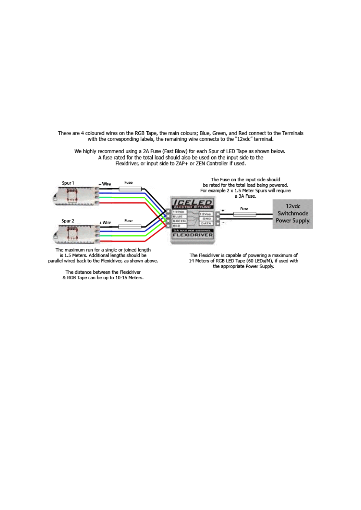
The 4 wires from the LED Tape can be extended if necessary by using any low-voltage 4- ore cable with a current rating of 3
Amps or greater. With long cable runs the use of a cable with a higher current rating will ensure minimal voltage-drop in the
wiring which could otherwise affect the colour rendering. 1.5M of RGB Tape i the maximum recommended length for
a continuous run (spur) or joined lengths of 60LED/M RGB LED Tape otherwise colours may not appear uniform along the
entire length and the Tape may be overloaded. If longer runs are required, and the power supply has adequate capacity,
additional lengths should be wired back directly to the supply or driver forming separate spurs. The tape itself is unsuited to
carrying more than 3 Amps so do not extend it with excess lengths or other types of current load.
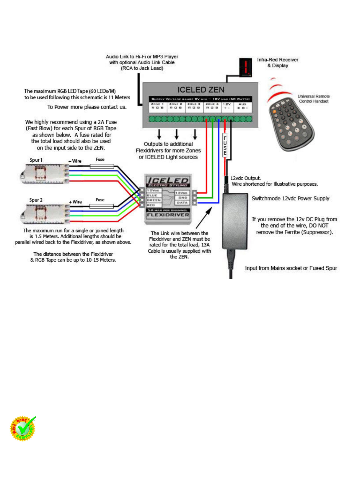
If a power supply having a significantly greater current capacity than the current requirement for the LED Tape is to be used
then a safety fuse will be required along the positive input wire to the product. This is to prevent excess current flowing in the
supply wiring or the LED Tape under fault conditions such as accidental damage. Such a fuse must be located as near to the
supply or driver to protect the installation wiring and shall have a current rating just higher than the load anticipated in the
spur. Each additional Spur will require its own separate fuse.
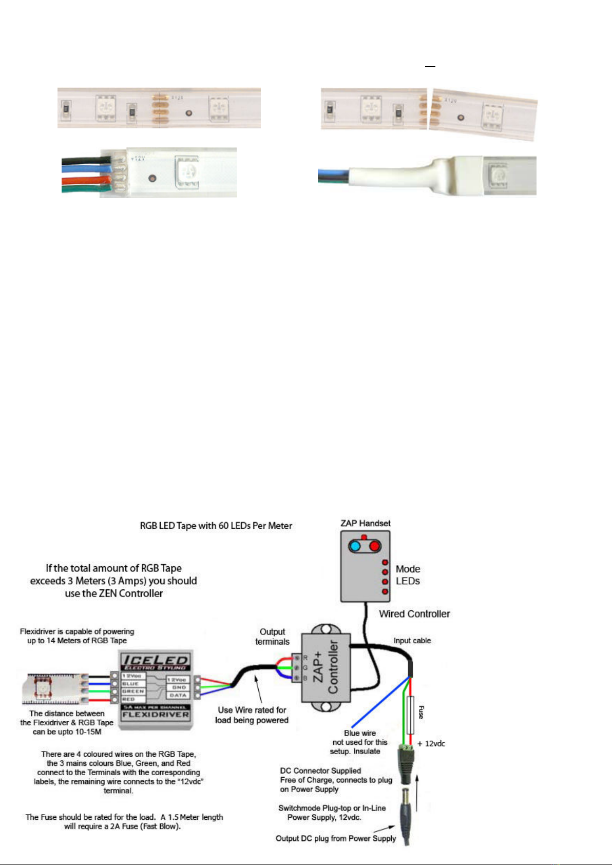
If linking the Flexidriver to a ZAP+ or ZEN ontroller, the cable or wire between the ontroller and the Flexidriver should be
rated according to the total load being powered, see cable and fuse ratings.
Note that a fuse may only be omitted from the low voltage side if the power supply provides its own overload protection and
is unable to significantly exceed the maximum rating of the wiring and LED product before it trips.
If hard-wiring the input of the Power Supply to the AC main it i e ential to u e a fu ed wall witch or outlet.
The fu e on the main ide hould be 3A or le . Only a qualified electrician hould hard-wire the Main PSU.
Power Supplie hould be in talled in a dry location.
WARNING
WARNINGWARNING
WARNING
Before use please remove the LED Tape from its bag and allow the odour to dissipate in an unused room or outdoor building.
Wash Hands after handling.
This product uses High Brightness LEDs. Direct viewing of the SMD LEDs at close range should be avoided.
Keep product away from children.
lean the LED Tape with damp a tissue only.
Litewave LTD. Will not accept responsibility for any other issues arising from improper use or fitting of this product where such
matters are beyond our control.
Having highlighted a number of safety issues and warnings in this installation guide Litewave LTD. will accept NO responsibility
for
issues arising from any failure to comply with these instructions and recommendations.

Flexible SILICONE
SILICONESILICONE
SILICONE RGB LED Tape – 60 LEDs Per Meter (20/03/12)
2
Wiring without the ICELED Flexidriver.
The best way for basic control (although only 7 colours will be available) is
to use a switch along each of the coloured wires. Each switch in turn should be connected to the negative of the power
supply. The remaining (+) wire from the LED Tape connects to the (+) positive 12 Volts on the Power Supply via a Fuse.
However we would advise using the I ELED Flexidriver which will generate a range of over 2 million colours by varying the
power to each of the 3 colours. For even further control use the Flexidriver in conjunction with an I ELED ZAP+ or ZEN
ontroller.
Wiring the LED Tape to the Flexidriver onnect the four colour coded wires to the corresponding labels on the Flexidriver
as shown below, make sure all the screws are tightened securely onto the wires – being careful not to trap the insulation
under the screw as this could cause a poor connection. The connector fitted to the RGB Tape should be removed enabling
connection as shown below. The remaining wire should be connected to the terminal labeled “12VD ”. Only one end of the
RGB Tape needs to be connected to the Flexidriver. NOTE: For clarity the + wire on the RGB LED Tape is shown as black.
Next you will need to connect the 12vdc power supply to the Flexidriver.
The positive (+) wire should be connected to the “12VD ” label on the Flexidriver, the remaining wire connects to the “GND”
label. Switch on the power to the power supply, the Tape should now light up if it does not immediately switch off power and
re-check all fuses and connections.
We do not advise using the product in a vehicle, you fit to a vehicle at your own risk.
PLEASE NOTE: If using in a vehicle or on a vehicle battery it i e ential to use an in-line fuse along the + input wire to the
Flexidriver or ontrollers (if used) as well as a fuse for each spur, if unsure consult a qualified vehicle electrician.
Follow the cable ratings on page 4 for the appropriate amperage fuse. If a ZEN or ZAP ontroller is fitted prior to the
Flexidriver the fuse should be on the input to the controller.
Cutting and connecting the Tape
Once cut the LED Tape will no longer be Spla h-proof. If cut or trimmed it hould not be in talled near to
ource of water or area where it i likely to come into contact with water.
Although we advise against cutting and reconnecting the LED Tape because this will affect your warranty, we have provided a
brief guide of how to cut and join the tape below. NOTE: When oldering alway do o in a well ventilated area and
wear a ma k.
Whether trimming to length or cutting the LED Tape into shorter lengths for reconnecting you need to cut the tape along the
line with the 4 solder pads on either side of the cut.

Flexible SILICONE
SILICONESILICONE
SILICONE RGB LED Tape – 60 LEDs Per Meter (20/03/12)
3
arefully remove 4-5mm of the silicone and resin taking care not to cut into the tracks of the pcb, this can be done with a
sharp stanley knife (always use sharp tools carefully). Make sure you have removed all of the silicone and resin on and
around the solder pads before soldering. Securing the LED Tape before soldering will make the task easier.
Be careful when soldering that you do not overheat the pads as this heat can damage the pad and the LEDs, a small dab of
flux paste helps with a fast solder connection. Make ure the wire you u e i rated for load.
Apply a small blob of solder to each copper solder pad. Before soldering the wire to the pads it is best to apply a small
amount of solder to each of the wires to tin the wires this will prevent the wires from becoming frayed and causing a short-
circuit.
A different coloured wire such as black should be soldered to the positive (+) pad. The + pad is identified on the P B with
the “+12v” marking. Then solder the blue, red, and green wires in that order to the remaining pads as shown in the
diagram. Be careful when soldering that you do not overheat the pads as this heat can damage the pad and the LEDs, a
small dab of flux paste helps with a fast solder connection. Ensure that the soldered connections are clean and there are no
wires touching which could cause a short circuit.
The soldered joints mu t be insulated to prevent accidental short-circuits. End caps are supplied for terminating trimmed
lengths, these can be partially filled with Hot Glue prior to fitting the end cap over the end of the LED Tape, carefully squeeze
out any excess glue. Alternatively adhesive lined heat shrink can be used (12 to 13mmmm Heat Shrink with 3:1 Shrink Ratio).
If using heat shrink cut a length around 35-40mm, place about 14mm of heat shrink over the end of the LED Tape then heat
gently with a heat gun until the shrink forms tightly around the LED Tape, then crimp the end with a pair of pliers forming a
closed end while the heat shrink is still very warm, cut off the excess heat shrink. Adhesive lined heat shrink can also be used
for insulating wired connections as shown above.
To get around corners, cut the LED Tape to the nearest 50mm then use connecting wire (rated for the load) to take the
voltage around the corner to another length of LED Tape. 1.5 Meters is the maximum total length that should be connected
together. Again any connections that are made should be insulated with adhesive lined heat shrink.
Connection to a
ZAP+ Controller:
NOTE: The maximum
length of RGB Tape that
can be connected using
this method is 3 Meters
due to the current handling
capacity of ZAP+.
To power the maximum
amount (3M) of Tape a
3.5A Power Supply is
required.

Flexible SILICONE
SILICONESILICONE
SILICONE RGB LED Tape – 60 LEDs Per Meter (20/03/12)
4
Connection to a ZEN Controller:
Warranty
This product is warranted from manufacturing defect only. This warranty is valid for 1 year from the date of purchase. This
warranty does not apply to damage caused by user installation or normal wear and tear. utting the tape will automatically
void your warranty, so do so carefully. If a segment becomes faulty only that part can be replaced under warranty once cut.
Litewave LTD. gives no warranty against damage to any surface due to applying or removing this product. Please follow
instructions and heed all warnings carefully.
Specification
Nominal supply voltage: 12 Volts D
Viewing Angle: 120 Degrees
Maximum current drain: Approx. 1.5 Amps (1500ma) per Meter
LED Type: SMD 5050 (60 LEDs per Meter)
Light Output: 360 Lumens/m
Durability: Lightly Splashproof (If Tape is cut connections need to be resealed).
Cable and Fu e (Fa t Blow) rating:
1.5 Meters = 2A 3 Meters = 3A 6 Meters = 6A 8 Meters = 8A 10 Meters = 10A

Flexible SILICONE
SILICONESILICONE
SILICONE RGB LED Tape – 60 LEDs Per Meter (20/03/12)
5
Re ource
To see the full Litewave product range visit http://www.litewave.co.uk
Important: In tallation by qualified electrician recommended.
IMPORTANT Safety Information:
- Keep away from children, thi i not a toy.
- DO NOT place or fit the LED Tape near ource of heat or naked flame . Do not in tall on flammable material.
- Not recommended for u e in direct unlight or in extreme temperature .
- Maximum length of Tape i 1.5 Meter do not exceed or extend.
- The Tape hould not be in talled around tight or angled bend a it may cau e the re in to crack. It mu t be in talled in a
traight line. DO NOT curl or twi t the LED Tape whil t power i on. The LED Tape can be bent on it’ flat ide but hould
not be flexed ideway .
- The LED Tape hould be removed from the reel before powering.
- Soldered connection hould not cau e a hort acro the track . Connection hould be ealed with hot glue or ilicone
and heat hrink or adhe ive lined heat hrink.
- A embly or connection mu t not damage or de troy conducting path on the circuit board. The LED Tape it elf and all it
component hould not be mechanically tre ed.
- In tallation of LED
Tape (with power upplie ) need to be made with regard to all applicable electrical and afety tandard .
- We advi e a qualified electrician perform entire in tallation.
- Correct electrical polarity need to be ob erved. Wrong polarity may damage the LED Tape.
- Parallel connection i highly recommended a afe electrical operation mode.
- Serial connection i not recommended. Unbalanced voltage drop can cau e hazardou overload and damage the LED Tape.
- Plea e en ure that the power upply i of ufficient power to operate the total load.
- * Only power the LED Tape with a 12vdc Switchmode Power Supply (con tant voltage). Do not u e a con tant current
Power Supply. Do not exceed the load of the Power Supply. The Power Supply hould conform to Cla 2 and SELV
tandard .
- Fixing to conductive or metal urface i not recommended. If fixing on metallic or otherwi e conductive urface , there
hould be an electrical in ulator between LED Tape and the mounting urface to prevent po ible hort-circuit.
- All LED are tatic en itive.
- Damaged by corro ion will not be honored a a material defect claim. It i the u er’ re pon ibility to provide uitable
protection again t corro ive agent uch a moi ture and conden ation and other harmful element .
-Identify Po itive (+) and negative (-) output of the Power Supply by u ing a multimeter.
-Electrical Connection and joint hould be in a dry area unle adequately ealed.
LITEWAVE LTD. MAKES NO WARRANTY, EITHER EXPRESSED OR IMPLIED, INCLUDING BUT NOT LIMITED TO ANY IMPLIED WARRANTIES OF
MERCHANTABILITY OR FITNESS FOR A PARTICULAR PURPOSE, REGARDING THESE LITEWAVE LTD. MAKES PRODUCTS AVAILABLE SOLELY
ON AN “AS-IS” BASIS. IN NO EVENT SHALL LITEWAVE LTD. BE LIABLE TO ANYONE FOR SPECIAL, COLLATERAL, INCIDENTAL, OR
CONSEQUENTIAL DAMAGES IN CONNECTION WITH OR ARISING OUT OF PURCHASE OR USE OF LITEWAVE PRODUCTS. THE SOLE AND
EXCLUSIVE LIABILITY TO LITEWAVE LTD, REGARDLESS OF THE FORM OF ACTION, SHALL NOT EXCEED THE PURCHASE PRICE OF THE
LITEWAVE PRODUCT DESCRIBED HERE IN.
Environmental Information
At the end of this product’s usable life it should be disposed of according to WEEE regulations, which means it should be taken to
your local municipal site for safe disposal/recycling.
Table of contents
Other Litewave Lighting Equipment manuals