manuals.online logo
Brands
  1. Home
  2. •
  3. Brands
  4. •
  5. Lithonia Lighting
  6. •
  7. Light Fixture
  8. •
  9. Lithonia Lighting WLTC Series User manual

Lithonia Lighting WLTC Series User manual

• All service shall be performed by qualified service personnel. This product must be in-
stalled and maintained in accordance with the applicable installation codes by a person
familiar with the construction operation of the product and the hazards involved.
• This product must be installed in accordance with the applicable installation codes and
ordinances.
• Before wiring to power supply, turn off electricity at fuse or circuit breaker.
• DisconnectA. C. power and unplug battery before servicing.
• Consult your local building code for approved wiring and installation.
• ULlisted for wet locations (-20°C-50°C)
• Do not let power supply cord touch hot surfaces.
• Do not mount near gas or electric heater.
• Equipment should be mounted in locations and at heights where it will not readily be subjected to tampering by unauthorized personnel.
• The use of accessory equipment not recommended by the manufacturer may cause an unsafe condition.
• Do not use this equipment for other than intended use.
• TheAC voltage rating of this equipment is specified on the product label. Do not connect equipment to any other voltage.
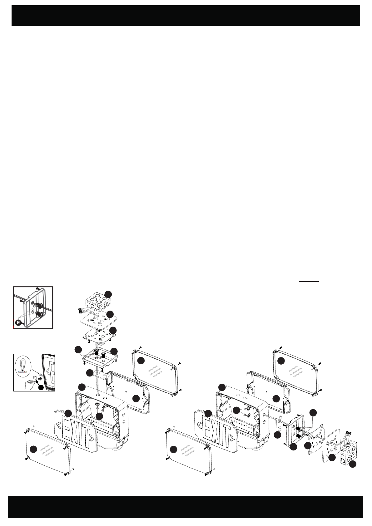
1. Use flathe ad screwdriver to loosen the screws on the LENSES (A).
2. Remove lens, from sign, set aside.
3. Remove EXIT STENCIL (B) from FIXTURE FRAME (C), set aside.
4. Drill or knockout appropriate knockouts on BACK PLATE (M) to fit junction box mounting points.
5. Drill or knockout holes in back plate for fixture supply wire leads.
6. Remove backing from self-adhesive JUNCTION BOX GASKET (F) and adhere to back plate.
7. Route fixture input wires through center hole of the back plate and make wiring connection. For 120V, use black and white wires and for 277V,
use red and white wires. WARNING: Properly insulate the unused lead with a wire nut (provided) or other approved means.
8. Secure back plate to JUNCTION BOX (J) (junction box and hardware not included).
9. Remove proper chevron(s) from the face plate as required. When removing chevrons it may be helpful to remove the color diffuser panel to
allow easier access to the chevrons. If removing color diffuser panel it is important to remember to reinstall the diffuser panel once chevron(s)
have been removed.
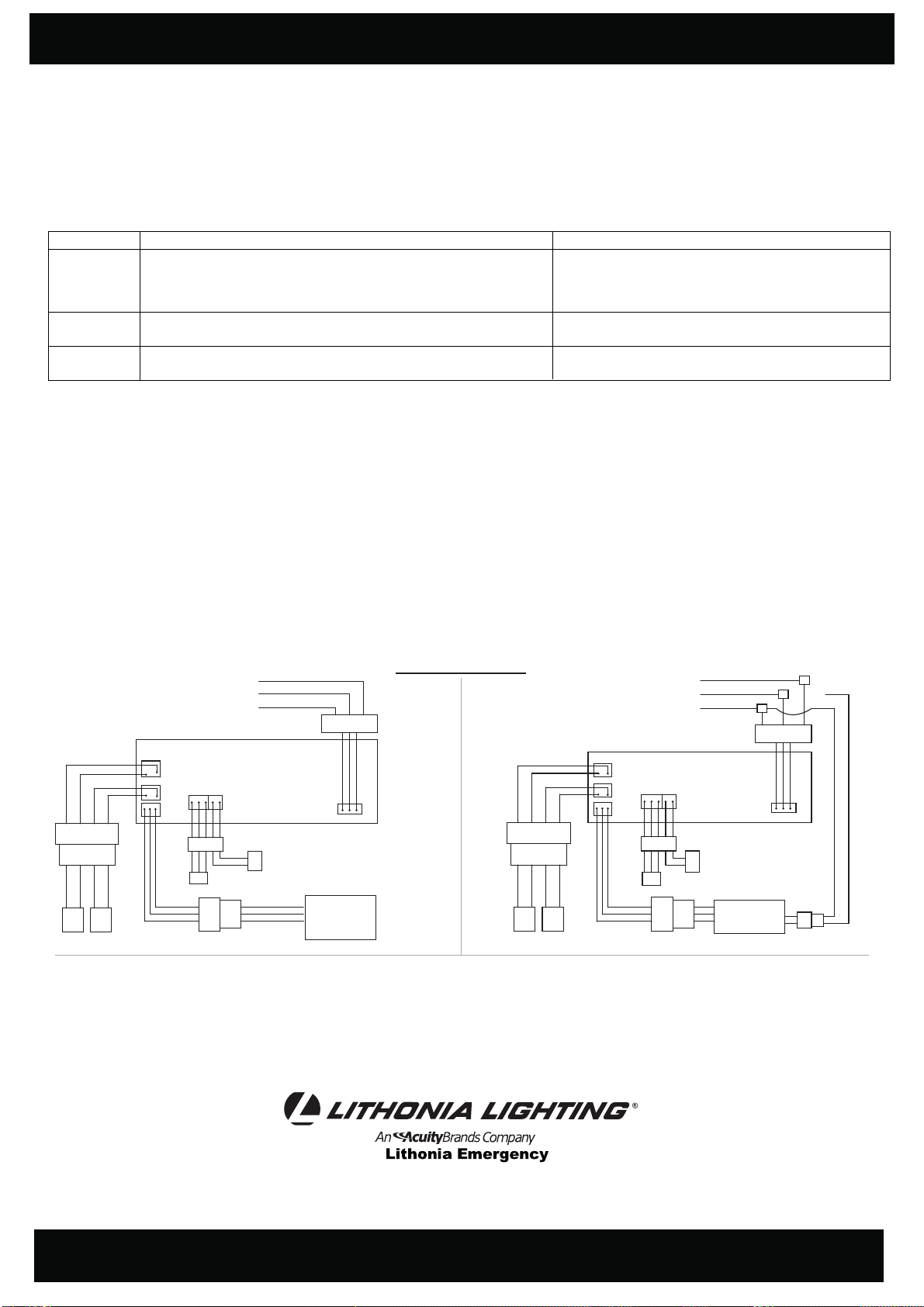
10. Connect battery to lamp board (see wiring diagrams on page 3).
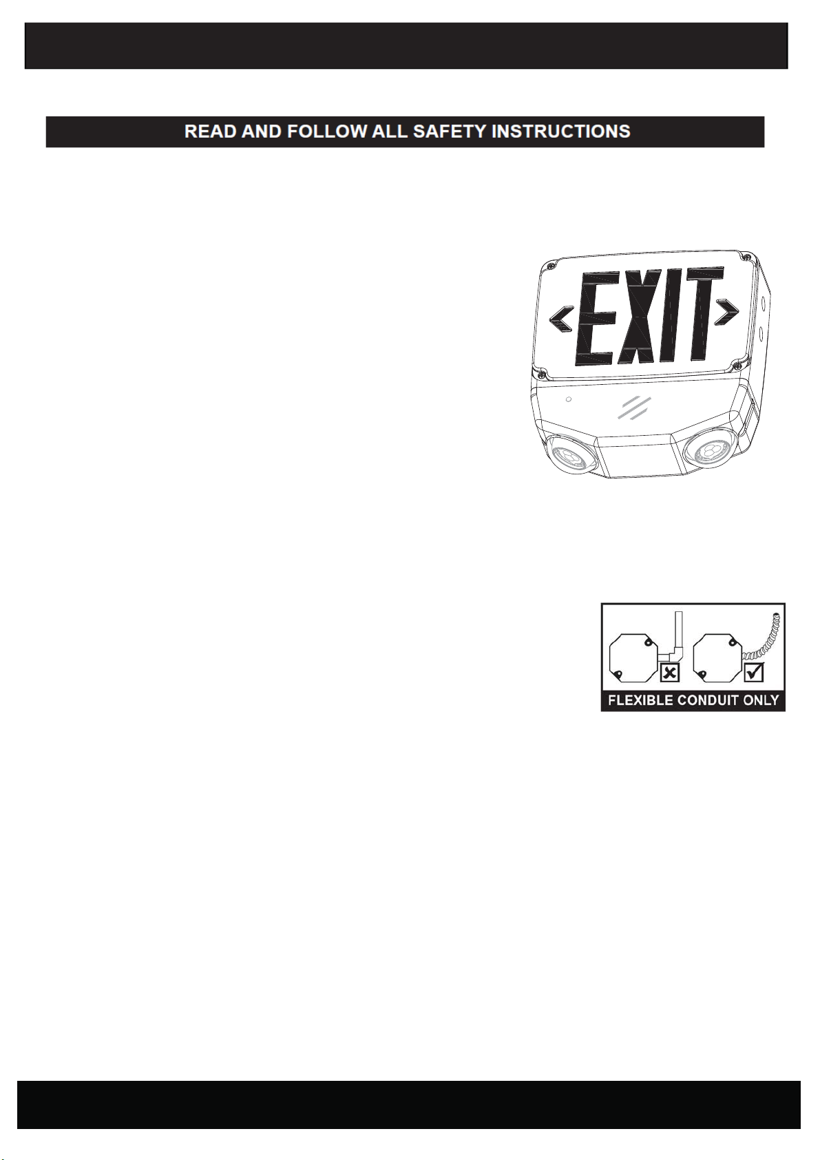
WET LOCATION LED COMBO EXIT & EMERGENCY LIGHT
NOTE : Max mounting height is 20 ft to achieve at least 1 ft-candle of illuminance in emergency mode.
WALL MOUNT INSTALLATION
WARNING: RISK OF ELECTRIC SHOCK- NEVER CONNECTTO, DISCONNECT FROM, OR SERVICE WHILE EQUIPMENT IS ENERGIZED.
WARNING: FAILURETO FOLLOW THESE INSTRUCTIONSAND WARNINGS MAYRESULTIN DEATH, SERIOUS INJURYOR SIGNIFICANT
PROPERTYDAMAGE - For your protection, read and follow these warnings and instructions carefully before installing or maintaining this
equipment. These instructions do not attempt tocover all installation and maintenance situations. If you do not understand these instructions or
additional information is required, contact Lithonia Lighting or your local Lithonia Lighting distributor.
SAVE THESE INSTRUCTIONS
and deliver to owner after installation
PAGE: 1 of 3
11. Secure face plate and back plate to the fixture frame.
12. Secure lens to fixture and securely torque screws.
13. Apply continuousAC power. Unit can be tested by holding the magnet (provided) near the LED indicator (where it’s marked as “Magnetic Test Switch”).
14. Magnet needs to be retained by building owner (or maintenance personnel) to perform monthly/annual inspections.
INSTALLATION INSTRUCTIONS for Lithonia Lighting WLTC models
CONDUIT ENTRY
1. Drill a ¾” hole through the desired conduit entry knock out located on the top or side of the frame of the sign.
2. Route theAC input conduit into housing.
3. All conduit connections must use ULLISTED and SUITABLE FOR WET LOCATION parts.
4. To finish installation of fixture, reference Wall, Ceiling or End Mount instructions.
INSTALLATION INSTRUCTIONS
CEILING OR END MOUNT INSTALLATION
1. Use flat head screwdriver to loosen the screws on the LENSES (A).
2. Remove lens, from sign, set aside.
3. Remove EXIT STENCIL (B) from FIXTURE FRAME (C), set aside.
4. Drill ¾” holes through the desired mounting knockouts located on the fixture frame. For ceiling mount, knockouts will belocated on the top of
the fixture frame. For wall mount, knockouts will be located on the side of the fixture frame.
5. Using provided hardware, thread NUTS (D) ontoPIPE NIPPLES (E). Slide pipe nipples through canopy holes.
6. Remove backing from self adhesive JUNCTION BOX GASKET (F) and adhere to back ofMOUNTING PLATE (G). Remove back-
ing from self adhesive PIPE THREAD GASKET (H) and adhere to front of MOUNTING CANOPY (I).
7. Place screws (provided) in holes on the mounting canopy.
8. Route fixture input wires through knockout in fixture frame, pipe nut and metal mounting plate.
9. Make wiring connection. For 120V, use black and white wires and for 277V, use red and white wires. WARNING: Properly insulate the
unused lead with a wire nut (provided) or other approved means.
10. Push wire connections into the J-BOX (J) (junction box not included). Secure mounting plate to junction box (hardware not included).
11. Secure the canopy to the steel mounting plate with screws installed in step 7.
12. Place pipe nipple through the mounting hole of the fixture frame until the gasket is touching the frame. Thread a second nut onto the pipe
nipple on the inside of the fixture frame to lock the canopy into place. Once canopy is locked into position there will not be any side-to-side
movement of the canopy.
13. Remove proper chevron(s) as required. When removing chevrons it may be helpful to remove the color diffuser panel toallow easier access to
the chevrons. If removing color diffuser panel it is important to remember to reinstall the diffuser panel once chevron(s) have been removed.
14. Connect battery to lamp board (see wiring diagrams on next page).
15. Secure face plate(s) to the fixture frame.
16. Secure lens to fixture and securely torque screws.
17. Apply continuousAC power.
Unit can be tested by holding the MAGNET (K) (p rovided) near the LED indicator
(where it’s marked as “Magnetic Test Switch”).
18. Magnet needs to be retained by building owner (or maintenance personnel) to perform monthly/annual inspections.
SAVE THESE INSTRUCTIONS
and deliver to owner after installation
PAGE: 2 of 3
Ceiling Mount
End Mount
K
PARTS LIST
A) Lens(es)*
B) Exit Stencil(s)*
C) Fixture Frame
D) Nuts (2)
E) Pipe Nipples (2)
F) Junction Box Gasket
G) Mounting Plate
H) Pipe Thread Gasket
I) Mounting Canopy
J) Junction Box**
K) Magnet
*1 for single-face or 2 for double-face
**Junction Box not included
A
B
C
D
E
F
G
H
I
J
M
A
A
B
C
D
M
A
E
H
I
F
G
J
INSTALLATION INSTRUCTIONS
OPERATION
1. ApplyAC power to the unit. The LED indicator will be GREEN.
2. After the battery has been left to charge for 2 hours, test the unit using the magnetic test switch. The LED indicator turns OFF, the LED board stays
ON and the lampheads should turn ON at this time.
3. When the magnet is removed, the LED indicator turns back to GREEN, the LED board stays ON and the lampheads should turn OFF at this time.
BATTERY
WET LOCATION COMBO PCBA
TRANSFORMER
WHITE COMM
BLACK 120VAC
RED 277VAC
LED INDICATOR
TEST SWITCH
LAMP HEAD
YELLOW
BLUE
YELLOW
BLUE
BATTERY CONNECTOR
LAMP HEAD
YELLOW
BLUE
YELLOW
BLUE
HEATING PAD
CONNECTOR
WET LOCATION COMBO PCBA
TRANSFORMER
BLACK 120VAC
WHITE COMM
RED 277VAC CHOOSE INPUT
VOLTAGE
LED INDICATOR
TEST SWITCH
BATTERY
ASSEMBLY
BATTERY CONNECTOR
Standard
SD Option (Self Diagnostics)
Wiring Diagrams
CW Option (Cold Weather)
CW SD Options (Cold Weather,
Self Diagnostics)
(MAGNETIC) (MAGNETIC)
Part No. EMCSA00916, REV. A
2018.10.15
SAVE THESE INSTRUCTIONS
and deliver to owner after installation
One Lithonia Way, Conyers GA 30012
Phone: 800-334-8694
www.lithonia.com
PAGE: 3 of 3
LED STATUS INDICATOR KEY and TROUBLESHOOTING:
Visual Status Indicaon Troubleshoong/Acons to Take
RED
GREEN
UNLIT
1. Baery connecon is not made.
2. Baery has been diagnosed as dead or defecve aer 24
hours of connuous charging with AC power supplied.
Baery is connected, AC power has been supplied and xture is in
charging state.
AC power has not been supplied.
1. Make connecon; or if baery is connected, disconnect
battery for eight seconds and then reconnect.
2. Replace the battery.
This is the normal state. No acon required.
Supply AC power.
MAINTENANCE
Caution:Always turn offAC power to the equipment before servicing. Servicing should be performed only by a qualified service technician. Use only
MANUFACTURER supplied replacement parts.
BATTERY: The battery supplied requires no maintenance. However, it should be tested periodically and replaced when it no longer operates the
connected sign for the duration of a 30-second or 90-minute test.
TESTING:
National Electric Code (NEC) and NFPA 101 current Life Safety code requirements require that routine tests need to be performed
as listed below: Once every month, the unit needs to be tested for duration of 30 seconds. Push in and hold the test switch to
perform this test. Once every 12 months, a full 90 minute (per UL requirements) test needs to be performed on the unit. Disconnect
power to the unit and leave it in the emergency mode. The lamps should stay ON for at least 90 minutes. Written records of the
testing are to be kept for examination by the authority having jurisdiction.

Other Lithonia Lighting Light Fixture manuals

Lithonia Lighting VAP User manual

Lithonia Lighting

Lithonia Lighting VAP User manual

Lithonia Lighting TWH Series User manual

Lithonia Lighting

Lithonia Lighting TWH Series User manual

Lithonia Lighting ELT627NY User manual

Lithonia Lighting

Lithonia Lighting ELT627NY User manual

Lithonia Lighting SGLL 24 PIR User manual

Lithonia Lighting

Lithonia Lighting SGLL 24 PIR User manual

Lithonia Lighting Shoplight User manual

Lithonia Lighting

Lithonia Lighting Shoplight User manual

Popular Light Fixture manuals by other brands

SAled Australia SL 62113 installation guide

SAled Australia

SAled Australia SL 62113 installation guide

EuroLite LED SCY-Bar TCL lightset user manual

EuroLite

EuroLite LED SCY-Bar TCL lightset user manual

LiteGear Newtura installation manual

LiteGear

LiteGear Newtura installation manual

Infinity S601 Profile manual

Infinity

Infinity S601 Profile manual

Intermatic WL150HPS installation instructions

Intermatic

Intermatic WL150HPS installation instructions

Sygonix 2583626 operating instructions

Sygonix

Sygonix 2583626 operating instructions

Blizzard Lighting SLIM PAR64 144 RGBW user manual

Blizzard Lighting

Blizzard Lighting SLIM PAR64 144 RGBW user manual

HQ Power VDPL3615MHZ user manual

HQ Power

HQ Power VDPL3615MHZ user manual

LIVARNO LUX HG06492A Operation and safety notes

LIVARNO LUX

LIVARNO LUX HG06492A Operation and safety notes

North Light 44-3700-1 quick start guide

North Light

North Light 44-3700-1 quick start guide

Show Tec Polar Wash 740 user manual

Show Tec

Show Tec Polar Wash 740 user manual

Esseci MONOD Assembly instructions

Esseci

Esseci MONOD Assembly instructions

DualLite DYN Series user manual

DualLite

DualLite DYN Series user manual

Delta Light RANDOM 124 ANO user manual

Delta Light

Delta Light RANDOM 124 ANO user manual

Delta Light DIRO DUO ST OK LED Installation instruction

Delta Light

Delta Light DIRO DUO ST OK LED Installation instruction

Claypaky SHARPY X SPOT instruction manual

Claypaky

Claypaky SHARPY X SPOT instruction manual

Forms + Surfaces LIGHT COLUMN BOLLARD installation instructions

Forms + Surfaces

Forms + Surfaces LIGHT COLUMN BOLLARD installation instructions

COLORKINETICS Accent Compact iColor installation instructions

COLORKINETICS

COLORKINETICS Accent Compact iColor installation instructions

manuals.online logo
manuals.online logoBrands
  • About & Mission
  • Contact us
  • Privacy Policy
  • Terms and Conditions

Copyright 2025 Manuals.Online. All Rights Reserved.