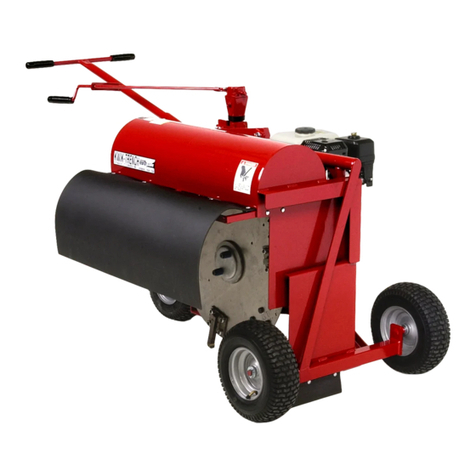
LITTLE BEAVER KT100 User manual

Kwik-Trench Mini-Trencher
OPERATORS MANUAL
WITH MAINTENANCE AND PARTS INFORMATION
P.O. Box 840, Livingston, TX 77351
Phone: 936.327.3121 Fax: 936.327.4025
MFG BY: Little Beaver, Inc. 0418
1.800.227.7515
LITTLEBEAVER.COM
KT100

CUSTOMERSERVICE
Ph: 936/327-3121 or Fax 936/327-4025
ORDERS...
Placeyourordersbytelephone,fax,ormail.Whencalling,pleasehaveyourpartsmanual
handyforreference.Ourhoursare8:00am-4:30pmcentral time, Monday thru Friday. When
orderingbymail or fax, includeadescription and KWIK TRENCHpartnumber for the items
youareordering,yourreturnaddress,andpaymentoryourauthorizationforCODshipment.
All orders are shipped UPS where possible. Freight charges will be added to your invoice.
Someitems are oversize, resulting in a higher shippingcost. Earth Saws are shippedvia
motorfreightduetotheirweight.
PAYMENT TERMS...
COD, Cash inAdvance, Visa, Mastercard, Discover,American Express or NET30 with
approvedcredit. COD limit fornew accounts is $500.00.Personal or company checkson new
accountswillbehelduntiltheyclearthe bank.Toeliminatethisdelay, you may pay by wire
transferor send a certified or cashiers check. For a NET 30 open account, please call or write
for a credit application.
SERVICE AND REPAIR...
YourKWIKTRENCHEarthSawhasbeendesigned for user repairwithordinary hand tools.
Nospecialtools are required. Consult theappropriatesection of the partsmanualfor instruc-
tions.
Serviceortechnicalconsulationisavailable, free of charge, from the factoryinLivingston,
Texas. Wewillbepleasedtohelpyouwithanyproblemsor questions. Just write, fax, orcall.
Ourhoursare8:00am-4:30pmcentraltime,MondaythruFriday.
Factoryrepairisavailable.Ifyoureturn a parttothefactory,pleaseincludethe following infor-
mation:Your name and return address, adescriptionoftheproblemandpayment or authoriza-
tionto return the repaireditem COD forthe repair and shippingcharges.
RETURNS...
Pleasecallthefactoryforareturnauthorization.Thiswillhelptoensurethatyourpartsare
handledproperly. Include yournameandaddress,customeraccount#,invoice#underwhich
thereturnedparts were ordered, anda brief description oftheproblem with the partsor the
reasonforreturningthem.Partstobeconsideredforwarrantymustbe returned to the factory
forinspection within 10 daysafter receipt of replacementparts. Be sure toprepay the shipping
charges,we will not accept collect or COD packages.
Ourmailingaddress...
LITTLE BEAVER, Inc.
2009SouthHouston
P. O. Box 840
Livingston,Texas77351
R0798
Page O-2

SAFETY ALERT SYMBOL
The symbol shown above is used to call your attention to instructions concerning your personal safety.
WATCH THIS SYMBOL — It points out important safety precautions.
Itmeans—ATTENTION! BECOMEALERT! YOUR PERSONALSAFETYIS INVOLVED!
Read the message that follows and be alert to the possibility of
Personal Injury or Death!
llllllllllllllllllllllllllllllllllllllllllllllllllllllllllllllllllllllllllllllllllllllllllllllllllllllllllllllllllllllllllllllllllllll
1 YEAR LIMITED WARRANTY
For1year frompurchase,LB EQUIPMENT,INC. willreplace fortheoriginal purchaser,
freeofcharge,any partorparts,found uponexaminationby any factoryauthorizedservice
center,or by the factory at Livingston, Texas, to be defective in material or workmanship or
both. If your equipment cannot be repaired, it will be replaced. All transportation charges on
partssubmitted for replacementunder thiswarranty mustbe borneby purchaser.
Thereisnootherexpresswarranty.
Impliedwarranties,includingthoseofmerchantabilityandfitnessforaparticularpurpose,
are limited to 1 year from purchase and to the extent permitted by law. Any and all implied
warrantiesareexcluded. Thisis the exclusiveremedy andliability for consequentialdamages
under any and all warranties are excluded to the extent exclusion is permitted by law.
*Notice: Enginesarewarrantied bythe manufacturerof the engine. Seeseparate engine
warranty enclosed.
llllllllllllllllllllllllllllllllllllllllllllllllllllllllllllllllllllllllllllllllllllllllllllllllllllllllllllllllllllllllllllllllllllll
MACHINESERIALNUMBER
Themachineserial number foryourKwik TrenchEarthSaw is locatedonthe rearshroud. Foryour convenience,
whenrequiringserviceofpartsinformation,refertothisnumberandyourmodelnumber. Recordthemodelnumber,
enginemake,machineserialnumberanddateofpurchaseinthespaceprovidedbelow:
0798
Page O-3
WARNING: The Engine Exhaust from this product contains chemicals known to
the State of California to cause cancer, birth defects or other reproductive harm.
R
MODEL NUMBER
MACHINE SERIAL NUMBER
ENGINE MAKE
DATE OF PURCHASE

R0798
Page O-4
TABLE OF CONTENTS
OPERATORS MANUAL
O-2 CustomerService Information
O-3 SafetyAlert,Warrantyand MachineInformation
O-4 Tableof Contents
O-5 SafetyInstructions
O-6 Maintenanceand Lubrication,Clutch
O-7 Maintenanceand Lubrication, Cutter Hub
O-8 AssemblyInstructions
O-9 TrenchingInstructions
PARTSMANUAL
Page #
P-1 Clutch/CutterHubAssembly
P-2 & 3 FrameAssembly
InsideBack Cover Torque InformationandConversionChart
Page #

SAFETY INSTRUCTIONS
DANGER: Failuretoobservesafetyinstructionsandreasonablesafetypracticescan
causePropertyDamage,SeriousBodilyInjuryand/orDeath. BE CAREFUL!! WATCHOUTFOR
BYSTANDERS!!
DANGER: NEVERdigtrencheswherethereisapossibilityofundergroundpowercables
orotherhazards. The exactlocationof undergroundservicesmust bedeterminedprior todrilling.
Inadvertentseveringoftelephone,fiberopticorCATVtransmissioncable,ordamagetosewerpipeis
costly;RUPTURINGOFGASORWATERLINESCANCAUSESERIOUSBODILYINJURYAND/OR
DEATH. COMINGINTOCONTACTWITHBURIEDPOWERLINESCANCAUSESERIOUSBODILY
INJURY,SEVEREBURNS,AND/ORELECTROCUTION. Calllocalutilitycompaniesoryourlocal"One-
Call"numberatleast48hoursbeforediggingandhaveundergroundutilitiesmarked.
DANGER: NEVERrunengineinsidebuildingorenclosedarea. Exhaustgasescontaincarbonmonoxide,
anodorlessanddeadly poison.
DANGER: KEEP hands and feet away from rotating blades. Serious bodily injury will result.
CAUTION:
1.READ andunderstand this operator’s manual and the operator’smanual
for the engine. If one is not available, please call or write for a free replacement.
2.NEVER Transport with engine running.
3. NEVER Trench on steep slopes. Trencher may overturn causing bodily injury.
4. NEVER Trench in solid rock or concrete.
5. NEVER Operate with broken teeth, belts or other damaged or missing parts.
6. KEEP Hands, Feet and Clothing away from moving parts while engine is running.
7. KEEP All safety shields and devices in place.
8.MAKE Certain everyone is clear beforeoperating the machine.
9. DO NOT Drop trencher off the back of a vehicle. Trencher's weight can exceed 350 lbs.
10. WEAR SAFETY GLASSES.
11. KEEP Bystanders at least 10 feet away from work area.
12. SHUT OFF Engine and disconnect spark plug wire to adjust, service, refuel or clean the machine.
Accidental engine starting is possible by rotating the cutter wheel.
13. AVOID The possibility of spilled fuel causing fire.
14.MAKESurewhentransportingtrencherinavehicleortrailer,itissafelysecuredwithstrapsorropes.
NOTICE
Itis theresponsibility ofthe contractor,owner anduser tomaintain andoperate theEarth Sawin compliancewith
operating instructions provided. Observe all listed safety instructions and other reasonable safety practices. LB
EQUIPMENT,INC.acceptsnoresponsibilityfordamagestothismachine,andotherpropertydamageand/orbodily
injuryduetocareless or improperoperations.
LB EQUIPMENT, INC. does not recommend or condone use of replacement engines greater than eight (8)
horsepower.
LBEQUIPMENT,INC.doesnot recommendorcondoneanyunauthorized modificationstotheearthsaw.
LBEQUIPMENT,INC.reservestherighttomakechangesindesignandchangesforimprovementsuponitsproduct
withoutimposing any obligationupon itself to install the same upon itsproducts theretofore manufactured.
Youroperatorsmanualoffersrecommendationsforprolongedandsatisfactoryservice.
Precaution is the best insurance against an accident.
0798
Page O-5
R

MAINTENANCE and LUBRICATION
DANGER: NEVER run engine inside building or enclosed area. Exhaust gases contain
carbon monoxide, an odorless and deadly poison.
Engines are shipped without oil or gasoline. Refer to MANUFACTURER'S INSTRUCTIONS for
proper procedures and recommended fluids.
IMPORTANT DO NOT drop the machine off the back of a vehicle, this may cause damage
to the body and frame. Machines should always be lifted, ramped or by a trailer.
LUBRICATING INSTRUCTIONS:
CHECK crankcase and gearbox oil level before each use.
CHANGE crankcase and gearbox oil as recommended by the manufacturer's instructions.
ADD grease to the pillow block bearings after every 100 hours of use.
CLEAN vertical frame posts and sleeves frequently to prevent binding. Do not use oil base lubri-
cants or grease. Silicone is recommended.
SHUT OFF ENGINE and disconnect spark plug wire to adjust, service, refuel or clean the
machine. Accidental engine starting is possible by rotating the cutter wheel.
ALL nuts, fasteners and fittings must be kept properly torqued. After every 25 hours of use the
engine nuts and bolts should be checked and tightened, if necessary. Add lock-tight to bolt threads.
FILTERS:
The air filter needs to be cleaned every 10 hours. More often in dusty dry conditions: Check engine
owners manual for further instructions.
Attach a remote air filter with pre-cleaner in serious dusty conditions, this will add to the engine life
considerably.
CLUTCH:
The slip clutch facings should be changed if the thickness is worn to 1/16" or less, this will maintain
the fast digging speed this type of unit can perform. Check every 20-25 hours of use.
ADJUSTMENT: Shoulder bolts must be kept tight. If the clutch wears to the point where
stopping the blades will not stall the engine within a few revolutions, tension
should be increased by adding a washer under each should bolt, or by
replacing the clutch facings.
R0798
Page O-6

0798
Page O-7
R
CUTTER HUB:
REMOVING THE CUTTER HUB:
Shoulditeverbenecessarytoremove the cutter hub, remove the three (3) cap
screwsand insert two (2) 1/4" - 20cap screws intothe threaded holes in the
bushingflange. Tightenthecapscrewsalternatelyandevenlysothepressagainst
theshoulder of the cutterhub,"jacking"thebushingfromthe hub.
INSTALLING THE CUTTER HUB:
Toinstallthecutterhub,assemblethebushing into the cutter hubsothatthethree
(3)counter-boredholesinthebushinglineupwiththethree(3) threaded holes in
thecutterhub. Insertthethree(3)capscrewsthroughthecounter-boredholesinto
thethreadedholesandscrewtheminfingertight. Slide thecutterhubandbushing
ontheshaftoverthe key. Locate the assemblysothe blades will clearthe base
andtheguard. Tightenthecapscrews insequencearound thecircle. Repeatuntil
nofurthermovementcanbeobtained(approx.12ft.lbs.).
BEARINGS:
Thenylon bearing (clear collar)must be inserted inthe blade with a slight bulge. After locating
thebearinginthecollaroftheblade,pressthebulgetoconformtothecontourofthe cutter hub.
MAINTENANCE and LUBRICATION Cont...

R0798
Page O-8
TRENCHER ASSEMBLYINSTRUCTIONS:
Installthree (3) tires with valvestemfacingout. Insertboltthroughtire wheel and frame axle.
Attachnut to bolt. Tirepressure should be 40 lbs.PSI.
Removetwo (2) bolts from open neck of frame. Insert the push handle, re-install bolts.
Attachlifthand lever.
Shroudandengine will now raiseandlower for digging depth.
Followingengine start up instructions. Fillcrankcase with oil. Add 10W30wt. oil to the6:1
gearreductionunitata1/3levelfull.
Followdiagram on pageP-1 on wear partassembly to installthe "SpringTynes Blades".
Doublecheckall bolts and fasteners. Add gasoline,openthrottle, may need to pullchoketo
start.
BLADE/TEETH ASSEMBLY:
CAUTION: Whenchangingbladesor making adjustmentsonthetrencher, the spark
plugmust be disconnected to prevent accidental starting of the engine.
Thebladesmustbe installed in the sequencelistedbelow (Clockwise looking at theslotsin the
blade holder) to insure proper operation of the trencher. The blade identification number is
stampedoneachbladenear the retaining notch.
SELECTION AND INSTALLATION OF SPRING TYNE BLADES
1/2" wide ditch - Use Blades #1, 2, 1, 2
1" wide ditch - Use Blades #1, 2, 3 & 4
2" wide ditch - Use Blades #3, 4, 5 & 6
3" wide ditch - Use Blades #2, 5, 6 & 7
DO NOT usediscblade trenchers with missingteeth. Ifyou do, this will increasethe
possibilityofengine vibration.
INSTRUCT operator to back off immovable objects to eliminate early teeth breakage.
To installnewblades,removethetwoclutchbolts,friction plate, clutch facing, disc and
bladeholder. Removethe old blades, insert thenewblades in the proper order, and remount
theblade holder on the hub.

0798
Page O-9
R
TRENCHING INSTRUCTIONS:
NOTE: Ifin hard ground, roots and other problemareas. DO NOT try and force
machine. Let the cutting blade do the cutting. Over pushing may cause
the blade to bog-down.
Puttrencherinposition.
Setthesteelchainfordiggingdepth. Ifthechainisleftunhooked, thefulldepthofeightincheswill
be obtained.
Turn fuel on. Use choke when startingengine if necessary.
Bringenginespeedupwiththethrottle.
Lower the machine slowly into the ground with the lifting lever. Brace your body against the
handle, keeping forward pressure on the handle. Allowing the machine to move backwards
duringloweringcancausethe blades to catch and stalltheengine.
Pushtrencherforward to end of yourtrench. Steady, even movement ofthemachine is neces-
saryfor best results. Bracing your bodyagainstthehandlewillhelpinobtaining a steady feed in
roughground.
Stoptheengineandturnthefueloffbeforemovingthemachine.

PARTS
INFORMATION
NOTES:

CLUTCH/CUTTER HUB ASSEMBLY
ITEM # PART # DESCRIPTION QTY
1 KT4-1032 ShoulderBolt,Socket Hd., 1/2x1 3/4 2
2 KT4-1031 Spring, Die 2
3 KT4-1017 FrictionPlate 1
4 KT4-1029 ClutchFacing 2
5 KT4-1014 Disc 1
6 KT4-1026 NylonBearing 1
7 KT4-1071 Dowel Pin, 1/4" x 5/8" 4
8 KT4-1013 BladeHolder 1
9 KT4-1015A Blade (Specify 1,2,3,4,5,6 or 7) 12" 4
10 KT4-1040 Cap Screw 3
11 KT4-1035 Motor Key 1
12 KT4-1030 Bushing, 3/4" Bore 1
13 KT4-1016 CutterHub 1
0399
Page P-1
R
-1
\
2
\
3
\
4
\
5
6
7
-9
\
10 11
-8
\
4
\
13
12
See Page O-8 for digging widths

R0798
Page P-2
FRAME ASSEMBLY
KT100
- 1
- 2
- 3
- 5
- 4
- 6
- 13 - 1
7
/
- 12 - 8
/
10
9 -
/
11

0798
Page P-3
R
ITEM # PART # DESCRIPTION QTY
FRAME ASSEMBLY
KT100
1 KT-011 PushHandleAssy. (w/ handle grips) 1
2 KT-010 HandleGrips 2
3 KT-032 Chain,5/16,8 links 1
4 KT-106 HeightAdjustmentHandle (w/ handle grip) 1
5 30194 HandleGrip 1
6 KT-108 FrameAssembly 1
7 KT-206 Kick Plate 1
8 KT-234 FrontSkirt 1
9 36412 Nut,Tire 3
10 KT-008 Tire 3
11 KT-025 Bolt,Tire 3
12 KT-232 Side Skirt 1
13 KT-212 Skirt Guard Frame 1

P.O. BOX 840 LIVINGSTON, TEXAS 77351
PH# 936/327-3121 FAX#936/327-4025
R
THINK
SAFETY
FIRST
Table of contents
Other LITTLE BEAVER Lawn And Garden Equipment manuals
Popular Lawn And Garden Equipment manuals by other brands

Treekeeper
Treekeeper TK-10169 Assembly instructions

FLORABEST
FLORABEST FLV 1200 A1 translation of original operation manual

Z.I.P.P.ER MASCHINEN
Z.I.P.P.ER MASCHINEN ZI-UVBW 1 Operation manual

EarthWise
EarthWise LSS020 owner's manual

Costway
Costway GT3902 user manual

Liberty Garden
Liberty Garden 880 instruction manual