manuals.online logo
Brands
  1. Home
  2. •
  3. Brands
  4. •
  5. LITTLE BEAVER
  6. •
  7. Lawn And Garden Equipment
  8. •
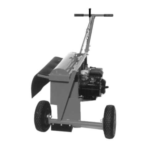
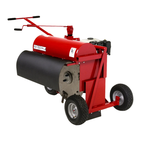
  9. LITTLE BEAVER KT2400B User manual

LITTLE BEAVER KT2400B User manual

Kwik-Trench Mini-Trencher
OPERATORS MANUAL
WITH MAINTENANCE AND PARTS INFORMATION
P.O. Box 840, Livingston, TX 77351
Phone: 936.327.3121 Fax: 936.327.4025
[email protected]
MFG BY: Little Beaver, Inc. 0418
1.800.227.7515
LITTLEBEAVER.COM
KT2400B
CUSTOMER SERVICE
Ph: 800/227-7515 or 936/327-3121 or Fax 936/327-4025
ORDERS...
Place your orders by telephone, fax, or mail. When calling, please have your parts
manual handy for reference. Our hours are 8:00 am - 4:30 pm central time, Monday
thru Friday. When ordering by mail or fax, include a description and KWIK TRENCH
part number for the items you are ordering, your return address, and payment or your
authorization for COD shipment.
All orders are shipped UPS where possible. Freight charges will be added to your
invoice. Some items are oversize, resulting in a higher shipping cost. Earth Saws are
shipped via motor freight due to their weight.
PAYMENT TERMS...
COD, Cash in Advance, Visa, Mastercard, Discover, American Express or NET 30 with
approved credit. COD limit for new accounts is $500.00. Personal or company
checks on new accounts will be held until they clear the bank. To eliminate this
delay, you may pay by wire transfer or send a certified or cashiers check. For a NET
30 open account, please call or write for a credit application.
SERVICE AND REPAIR...
Your KWIK TRENCH Earth Saw has been designed for user repair with ordinary hand
tools. No special tools are required. Consult the appropriate section of the parts
manual for instructions.
Service or technical consulation is available, free of charge, from the factory in
Livingston, Texas. We will be pleased to help you with any problems or questions.
Just write, fax, or call. Our hours are 8:00am - 4:30pm central time, Monday thru Fri-
day.
Factory repair is available. If you return a part to the factory, please include the fol-
lowing information: Your name and return address, a description of the problem and
payment or authorization to return the repaired item COD for the repair and shipping
charges.
RETURNS...
Please call the factory for a return authorization. This will help to ensure that your
parts are handled properly. Include your name and address, customer account #,
invoice # under which the returned parts were ordered, and a brief description of the
problem with the parts or the reason for returning them. Parts to be considered for
warranty must be returned to the factory for inspection within 10 days after receipt of
replacement parts. Be sure to prepay the shipping charges, we will not accept collect
or COD packages.
LITTLE BEAVER, Inc.
2009 South Houston
P. O. Box 840
Livingston, Texas 77351
R0798
Page O-2
SAFETY ALERT SYMBOL
The symbol shown above is used to call your attention to instructions concerning your personal safety.
WATCH THIS SYMBOL  It points out important safety precautions.
It means  ATTENTION! BECOME ALERT! YOUR PERSONAL SAFETY IS INVOLVED!
Read the message that follows and be alert to the possibility of Personal Injury or Death!
llllllllllllllllllllllllllllllllllllllllllllllllllllllllllllllllllllllllllllllllllllllllllllllllllllllllllllllllllllllllllllllllllllll
1 YEAR LIMITED WARRANTY
For 1 year from purchase, LB EQUIPMENT, INC. will replace for the original purchaser,
free of charge, any part or parts, found upon examination by any factory authorized service
center, or by the factory at Livingston, Texas, to be defective in material or workmanship or
both. If your equipment cannot be repaired, it will be replaced. All transportation charges on
parts submitted for replacement under this warranty must be borne by purchaser.
There is no other express warranty.
Implied warranties, including those of merchantability and fitness for a particular purpose,
are limited to 1 year from purchase and to the extent permitted by law. Any and all implied
warranties are excluded. This is the exclusive remedy and liability for consequential damages
under any and all warranties are excluded to the extent exclusion is permitted by law.
*Notice: Engines are warrantied by the manufacturer of the engine. See separate engine
warranty enclosed.
llllllllllllllllllllllllllllllllllllllllllllllllllllllllllllllllllllllllllllllllllllllllllllllllllllllllllllllllllllllllllllllllllllll
MACHINE SERIAL NUMBER
The machine serial number for your Kwik Trench Earth Saw is located on the rear shroud. For your
convenience, when requiring service of parts information, refer to this number and your model number.
Record the model number, engine make, machine serial number and date of purchase in the space
provided below:
MODEL NUMBER ________________________ ENGINE MAKE ________________________
MACHINE SERIAL NUMBER ____________________ DATE OF PURCHASE ______________
0798
Page O-3
WARNING: The Engine Exhaust from this product contains chemicals known to
the State of California to cause cancer, birth defects or other reproductive harm.
R
R0798
Page O-4
TABLE OF CONTENTS
OPERATORS MANUAL
O-2 Customer Service Information
O-3 Safety Alert, Warranty and Machine Information
O-4 Table of Contents
O-5 Safety Instructions
O-6 Maintenance and Lubrication, Clutch
O-7 Maintenance and Lubrication, V-Belt
O-8 Maintenance and Lubrication, V-Belt, Cutter Hub,
Bearing
O-9 Assembly
O-10 Trenching Instructions
PARTS MANUAL
Page #
P-1 & 2 Frame Assembly
P-3 Clutch/Cutter Hub Assembly
P-4 Cutter Wheel Assembly
Inside Back Cover Torque Information and Conversion Chart
Page #
SAFETY INSTRUCTIONS
DANGER: Failure to observe safety instructions and reasonable safety practices can
cause Property Damage, Serious Bodily Injury and/or Death. BE CAREFUL!! WATCH OUT FOR
BYSTANDERS!!
DANGER: NEVER dig trenches where there is a possibility of underground power cables
or other hazards. The exact location of underground services must be determined prior to
drilling. Inadvertent severing of telephone, fiber optic or CATV transmission cable, or damage to
sewer pipe is costly; RUPTURING OF GAS OR WATER LINES CAN CAUSE SERIOUS BODILY INJURY
AND/OR DEATH. COMING INTO CONTACT WITH BURIED POWER LINES CAN CAUSE SERIOUS BODILY
INJURY, SEVERE BURNS, AND/OR ELECTROCUTION. Call local utility companies or your local "One-
Call" number at least 48 hours before digging and have underground utilities marked.
DANGER: NEVER run engine inside building or enclosed area. Exhaust gases contain carbon
monoxide, an odorless and deadly poison.
DANGER: KEEP hands and feet away from rotating blades. Serious bodily injury will result.
CAUTION:
1. READ and understand this operators manual and the operators manual
for the engine. If one is not available, please call or write for a free replacement.
2. NEVER Transport with engine running.
3. NEVER Trench on steep slopes. Trencher may overturn causing bodily injury.
4. NEVER Trench in solid rock or concrete.
5. NEVER Operate with broken teeth, belts or other damaged or missing parts.
6. KEEP Hands, Feet and Clothing away from moving parts while engine is running.
7. KEEP All safety shields and devices in place.
8. MAKE Certain everyone is clear before operating the machine.
9. DO NOT Drop trencher off the back of a vehicle. Trencher's weight can exceed 350 lbs.
10. WEAR SAFETY GLASSES.
11. KEEP Bystanders at least 10 feet away from work area.
12. SHUT OFF Engine and disconnect spark plug wire to adjust, service, refuel or clean the
mahine. Accidental engine starting is possible by rotating the cutter wheel.
13. AVOID The possibility of spilled fuel causing fire.
14. MAKE Sure when transporting trencher in a vehicle or trailer, it is safely secured with straps
or ropes.
NOTICE
It is the responsibility of the contractor, owner and user to maintain and operate the Earth Saw in
compliance with operating instructions provided. Observe all listed safety instructions and other
reasonable safety practices. LB EQUIPMENT, INC. accepts no responsibility for damages to this machine,
and other property damage and/or bodily injury due to careless or improper operations.
LB EQUIPMENT, INC. does not recommend or condone use of replacement engines greater than eight (8)
horsepower.
LB EQUIPMENT, INC. does not recommend or condone any unauthorized modifications to the earth saw.
LB EQUIPMENT, INC. reserves the right to make changes in design and changes for improvements upon
its product without imposing any obligation upon itself to install the same upon its products theretofore
manufactured.
Your operators manual offers recommendations for prolonged and satisfactory service.
Precaution is the best insurance against an accident.
0798
Page O-5 R
MAINTENANCE and LUBRICATION
DANGER: NEVER run engine inside building or enclosed area. Exhaust gases
contain carbon monoxide, an odorless and deadly poison.
Engines are shipped without oil or gasoline. Refer to MANUFACTURER'S INSTRUC-
TIONS for proper procedures and recommended fluids.
IMPORTANT DO NOT drop the machine off the back of a vehicle, this may cause
damage to the body and frame. Machines should always be lifted, ramped or
transported by a trailer.
LUBRICATING INSTRUCTIONS:
CHECK crankcase and gearbox oil level before each use.
CHANGE crankcase and gearbox oil as recommended by the manufacturer's instructions.
ADD grease to the pillow block bearings after every 100 hours of use.
CLEAN vertical frame posts and sleeves frequently to prevent binding. Do not use oil
base lubricants or grease. Silicone is recommended.
SHUT OFF ENGINE and disconnect spark plug wire to adjust, service, refuel or
clean the machine. Accidental engine starting is possible by rotating the cutter
wheel.
ALL nuts, fasteners and fittings must be kept properly torqued. After every 25 hours of
use the engine nuts and bolts should be checked and tightened, if necessary. Add lock-
tight to bolt threads.
AIR FILTER: The air filter needs to be cleaned every 10 hours. More often in dusty dry
conditions: Check engine owners manual for further instructions.
Attach a remote air filter with pre-cleaner in serious dusty conditions, this will add to the
engine life considerably.
CLUTCH: The slip clutch facings should be changed if the thickness is worn to 1/16" or
less, this will maintain the fast digging speed this type of unit can perform. Check every
20-25 hours of use.
ADJUSTMENT: Shoulder bolts must be kept tight. If the clutch wears to the point
where stopping the blades will not stall the engine within a few revolutions,
tension should be increased by adding a washer under each shoulder bolt, or by
replacing the clutch facings.
R0798
Page O-6
Page O-7 R
MAINTENANCE CONT...
V-BELT CARE: V-belts may be the item most overlooked during equipment mainte-
nance, but proper care and maintenance of V-belts and their sheaves (pulleys) can
yield great rewards. The nature of V-belts makes preventive maintenance relatively
easy. V-belts and sheaves wear gradually and usually give advance warning of
failure.
Nonetheless, it is important to recognize the warnings. All belts and sheaves will wear
as part of their lifes cycle. As wear occurs, the belts will ride lower in the grooves. A
worn belt is, in effect, longer than a new one.
V-belts grip by wedging in the pulley grooves. Belts that are too loose cause slippage,
loss of power, loss of speed and rapid wear to both the belt and the sheave. A howl or
squeal indicates that the belt is too loose or the load is too heavy.
ALIGNMENT AND TENSION: Check to be sure sheaves are properly aligned be-
cause misalignment can cause excessive wear to the belt sidewall. Unusual wear of
the belt outer cover is an indication of more serious mechanical trouble. V-belts are
designed to operate by making clean, dry surface contact with the sidewall of the
sheaves. Inspect belts periodically to assure that they are not contaminated with
grease or oil. Don't allow mud, rust or any other foreign matter to build up in sheave
grooves. Clean sheaves carefully with a wire brush.
SIGNS OF TROUBLE: Don't install new V-belts without carefully inspecting the
sheaves. Focus special attention on these conditions: ~ worn groove sidewalls ~ a
shiny sheave groove bottom ~ wobbling sheaves or ~ damaged sheaves. Sheave
sidewalls must be perfectly straight because the wedging action of the V-belt is
impaired and its gripping power is reduced when the walls are worn or dished out.
A shiny sheave groove bottom is an indication that the belt, sheave or both are badly
worn and the belt is bottoming in the groove. This condition may first be evident on
the smaller sheave.
Sheave wobble may be caused by ~ improper installation on the shaft ~ a worn/
damaged bushing ~ a worn/damaged sheave hub or by ~ a bent shaft. Any of these
conditions will cause early failure. The wobbling
sheave whips the belt
from side to side,
subjecting the belt to
lateral strain and causing
rapid wear to both the
sheave and belt. Vibration
is another indication of an
improperly installed or
damaged sheave; however,
vibration can also be caused by a damaged belt.
0798
R0798
Page O-8
V-BELT CARE CONT...
Check the alignment of the sheaves. The drive and driven shafts should be parallel
both horizontally and vertically, and the centers of both sheaves should be in a straight
line. Although V-belts can tolerate minor misalignment (About 1/16 inch per 12 inches
of shaft center distance), close-to-perfect alignment will prolong belt life.
Set the belt take-up adjustment at its minimum position and place the new belt in the
correct position by hand. Never pry belts over the sheave with a screwdriver or other
hard object.
All V-belt drives must operate with correct belt tension to provide the optimum wedg-
ing action of the belt against the groove sidewalls. Allow a reasonable break in period
of a few hours, and then check for proper belt tension. New belts tend to elongate
slightly until they are seated in the sheave groove and initial stretch is removed from
the belt. Be sure to reinstall all protective guards and shields.
CUTTER HUB:
REMOVING THE CUTTER HUB: Should it ever be necessary to remove the
cutter hub, remove the three (3) cap screws and insert two (2) 1/4" - 20 cap screws into
the threaded holes in the bushing flange. Tighten the cap screws alternately and evenly
so the press against the shoulder of the cutter hub, "jacking" the bushing from the hub.
INSTALLING THE CUTTER HUB: To install the cutter hub, assemble the bush-
ing into the cutter hub so that the three (3) counter-bored holes in the bushing line up
with the three (3) threaded holes in the cutter hub. Insert the three (3) cap screws
through the counter-bored holes into the threaded holes and screw them in finger tight.
Slide the cutter hub and bushing on the shaft over the key. Locate the assembly so the
blades will clear the base and the guard. Tighten the cap screws in sequence around
the circle. Repeat until no further movement can be obtained (approx. 12 ft. lbs.).
BEARINGS:
The nylon bearing (clear collar) must be inserted in the blade with a slight inward
bulge. After locating the bearing in the collar of the blade, press the bulge to conform
to the contour of the cutter hub.
Page O-9 R
TRENCHER ASSEMBLY INSTRUCTIONS:
Remove the washers and pins that are on the front axles. Install two (2) front tires
with valve stem facing out. Re-install washers & pins. Install rear tire by inserting
axle bolt through wheel bearings and swivel. Install and tighten lock nut, leaving a
small amount of play in wheel bearings. Tire pressure should be 40 lbs. PSI.
Remove two (2) bolts from open neck of frame. Insert the push handle, re-install
bolts.
Attach hand crank and swivel end to manual actuator. Use hand crank to raise
shroud and engine all the way.
Follow engine manufacturers start up instructions. Fill crankcase with the recom-
mended oil. Add 30 wt. oil to the 6:1 gear reduction unit til it is 1/3 full.
Follow diagrams on page P-1.2 & 3 to install wear parts and the "Super Blade Plus" or
the "Super Extra Rock Blade" on P-4.
Double check all bolts and fasteners. Make sure the blade is properly installed and
the shoulder bolts are tightened.
BLADE/TEETH ASSEMBLY:
CAUTION: When removing or installing the blade or when making adjust
ments on the trencher, the spark plug must be disconnected to prevent acci
dental starting of the engine.
When determining which teeth are right hand or left hand, stand in the operating posi-
tion (standing behind the push handle and facing the direction of travel). The teeth
that are on the right hand side of the blade are the RIGHT TEETH. The teeth that are on
the left hand side of the blade are the LEFT TEETH.
To install new teeth, remove the two (2) shoulder bolts, die springs, friction plate,
clutch facings, and the blade. Remove the old teeth from the blade, install the new
teeth in the proper order, and remount the blade on the cutter hub.
The width of your trench is determined by the curvature of the tooth. You will have
straight teeth, curved in teeth (teeth that curve into the blade) and curved out teeth
(teeth that curve away from the blade).
For the KT200B Super Blade Plus (SBP) which has twelve (12) teeth, start placing your
teeth on the blade and keep a clock in mind. One o'clock, Two o'clock, etc. Follow
the diagram on page P-4 for this model. Standard cut is 2 inches.
The KT200B Super Xtra Rock Teeth (SXRT) only has four (4) "Super Xtra Rock Teeth"
0798
RPage O-10
TRENCHER OPERATING INSTRUCTIONS:
Put trencher in position.
Turn fuel on. Use choke when starting engine if necessary.
Allow engine to warm up for 2-3 minutes, then bring engine speed up with the
throttle.
Stand behind the push handle and lower trencher by turning the crank handle
counter-clockwise to required depth. Keep left hand on the handle for stability.
Push trencher forward to end of your trench.
NOTE: If in hard ground, roots and other problem areas, DO NOT attempt to
force machine. Allow the cutting blade do the cutting, over pushing may
cause the blade to bog-down.
INSTRUCT operator to back off immovable objects to eliminate early teeth breakage.
Raise the blade by turning crank handle clockwise until cutting blade is completely
out of the ground.
Stop the engine and turn the fuel off before moving the machine.
DO NOT use disc blade trenchers with missing teeth. If you do, this will
increase the possibility of engine vibration.
0798
PARTS
INFORMATION
NOTES:
R0600
Page P-1
15-
--
\
16
---1
---2
---4
5
\
6---
---7
---10
12
I
---13
14
\
19---
---32
27---
33---
---20
11---
---30
28
---21
---23
31---
--22
---36
24
\
25
\
30---
37---
35
\
26
35
/
\
34
\
8
--9
FRAME ASSEMBLY - KT2400B
/
2
---3
---9
15---
---15
15---
\
38
---16
34
\
\
18
45 ---
47 ---
\----39
44---
--- 41
--- 43
\
47
--- 45
---47
--- 46
---35
43 ---
I
---40
--17
1100
Page P-2
R
FRAME ASSEMBLY KT2400B
ITEM # PART # DESCRIPTION QTY
1 KT286 Push Handle Assy. (w/ handle grips) 1
2 KT010 Handle Grips 3
3 KT2448 Crank Handle Assy. (w/ handle grip) 1
4 KT006 Swivel, U-Joint 1
5 KT045 Actuator Complete, 8" 1
KTAH812 Gear Head, Actuator 1
KT045C Cylinder, Actuator, 8" 1
KTAB812 Bevel Housing, Actuator 1
6 KT009 U-Bolt, Actuator, 3/8" NC 1
7 KT2423 Frame Assembly 1
8 35175 Bushing, Front Wheel, 7/8" long 2
9 KT046 Wheel, 12" Pneumatic 3
10 9096 Nut, Hex 3/4 NC Nylon Lock 1
11 KT041 Bolt, Hex, 3/4 x 6-1/2, NC Gr. 5 1
12 KT2416 Skirt, Front 1
13 KT2422 Skirt, Side 1
14 KT2412 Frame, Skirt 1
15 KT021 Bolt, Carriage, 1/4 x 3/4 12
16 30204 Nut, Hex, 1/4 NC, Nylon Lock 6
17 8048 Washer, Flat, 5/8 SAE 2
18 6533 Bolt, Hex, 1/2 x 2-1/2, NC Gr. 5 1
19 9026-KEP Nut, Hex, 1/4 NC, KEP 8
20 KT250 Swivel, Rear 1
21 36221 Washer, Thrust, 1/32" 2
22 36223 Washer, Thrust, 3/32 1
23 KT040 Roll Pin, 1/4 x 1-1/2 1
24 KT265 Pin, Lock 1
25 KT039 Roll Pin, 3/16 x 1 1
26 KT278 Angle, Actuator Mounting, R.H. 1
27 KT279 Angle, Actuator Mounting, L.H. 1
28 KT2450 Bar, Pointer, (as a weldment) 1
30 KT285 Bushing, Rear Wheel, 1-3/8" long 2
31 KT022 Bolt, Hex, 3/8 x 2-1/4 NC Gr. 5 2
32 4018-1H Bolt, Hex, 1/4 x 1-1/4 NC Gr. 5 2
33 9024-1 Bolt, Hex, 5/16 x 1 NC Gr. 5 4
34 KT2440 Rocker Arm, Actuator 4
35 30154 Nut, Hex, 3/8 NC, Nylon Lock 4
36 30158 Nut, Hex, 1/2 NC, Nylon Lock 1
37 30163 Cotter Pin, 1/8 x 1 2
38 30164 Washer, Flat, 3/4" 2
39 9027-8 Bolt, Hex 3/8 x 1-1/4 NC Gr. 5 1
40 KT1250 Link, Actuator 1
41 KT1257 Pin 1
43 30153 Washer, Flat 1/2" SAE 4
44 KT2441 Bar, Height Adjustment Linkage 1
45 KT1259 Pin 2
46 3002-B Washer, Flat, 3/8 Heavy 1
47 9059-1 Hairpin Cotter 3
\
11
\
2
\
3
---21
---20
2
\
4
\
9
\
10
\
19
\
17---
---15
\
6
12
\
13---
1 4---
7---
---16
---8
12
\
18
\
R0700
Page P-3
See page O-7 of this
manual for Drive
Belt information
and instructions.
BELT DRIVE ASSEMBLY
KT2400B
---22
---24
1---
B---
---F
---D
---C
A---
E---
D---
G---
22---
\
5
23--
1100
Page P-4
R
BELT DRIVE ASSEMBLY KT2400B
ITEM # PART # DESCRIPTION QTY
1 KT2420 Top Hat Assy. 1
A KT2426 Base, Top Hat 1
B KT2427 Plate, Upper, Top Hat 1
C 30151 Nut, Hex, 1/2" NC 2
D 30153 Washer, Flat, 1/2" SAE 4
E 30158 Nut, Hex, 1/2 NC Nylon Lock 2
F KT248 Pin, Hinge 1
G 30163 Cotter Pin, 1/8" x 1" 2
2 KT056 Bolt, Hex, 1/4" x 1-3/8" NC Gr. 8 (incl w/ Item #3) 6
3 KT002 Bushing, SDS 1" Pulley w/ Bolts 1
4 KT066 Pulley, 4" Diameter, 3-Belt 2
5 KT4-3V300B V-Belt, Rubber, 3V, Banded 1
6 KT2421 Bar, PTO Shaft, 1" OD 1
7 KTP205 Bearing, 1" Pillow Block 2
8 KT2446 Bar, Pillow Block 2
9 KT002-3 Bushing, SH 1" Pulley w/ Cap Screws 1
10 9021 Screw, Set, Socket Head, 1/4" x 1/4" NC 2
11 KT065 Pulley, 5.0" Diameter, 3-Belt 1
12 KT230 Key, PTO Shaft 2
13 KT1221 Shroud, Pulley 1
14 9026-KEP Nut, Hex, 1/4" NC, KEP Lock 4
15 9024-BP Bolt, Hex, 1/4" x 1" NC Gr. 5 4
16 6533 Bolt, Hex, 1/2" x 2-1/2" Gr. 5 4
17 30153 Washer, Flat, 1/2" SAE 4
18 30158 Nut, Hex, 1/2" NC Nylon Lock 4
19 4081 Key, Engine Shaft 1
20 3002-B Washer, Flat, 3/8" SAE 4
21 30154 Nut, Hex, 3/8" NC, Nylon Lock 4
22 3002-B Washer, Flat, 3/8" SAE 8
23 30154 Nut, Hex, 3/8 NC, Nylon Lock 4
24 30295 Bolt, Hex, 3/8 x 1-1/2 NC Gr. 5 4
R0600
Page P-5
CLUTCH/CUTTER HUB ASSEMBLY
ITEM # PART # DESCRIPTION QTY
1 KT4-1032 Bolt, Socket Head Shoulder, 1/2 x 1 3/4 2
2 KT4-1031 Spring, Die 2
3 KT4-1017 Friction Plate 1
4 KT4-1029 Clutch Facing 2
5 KT4-1026 Nylon Bearing 1
6 KT4-1040 Cap Screw, Socket Hd., 5/16 x 1 1/2 3
7 KT231 Motor Key 1
8 KT003 Bushing, 1" Bore, P1-1 1
9 KT4-1016 Cutter Hub 1
\
7
\
9
\
4
\
8
\
6
\
5
\
1
\
2
\
3
\
4
Cutter Wheel collar should
face the engine.
See pages following for
cutter wheel information.
0700 Page P-6 R
SBSL
SBSR
SBSR
SBCIR
SBCIL
SBSL
SBSR
SBSR
SBSR
SBSR
SBSL
SBSL
SBSL
SBSL
SBCIL
KT2400B SUPER BLADE PLUS (SBP)
BLADE ASSEMBLY (2 digging width)
KT2400B SUPER BLADE PLUS (SBP)
BLADE ASSEMBLY (2 1/2 digging
width)
PART # DESCRIPTION QTY
KT29S2 Cutter Wheel-2" width 1
KT29S1 Cutter Wheel-1" width 1
KTS241 Teeth Set w/ nuts & bolts 1
KTS242 Teeth Set w/ nuts & bolts 1
KTSBP-SR Tooth, Straight Right 6
KTSBP-SL Tooth, Straight Left 6
KTSBP-CIL Tooth, Curved in Left 2
KTSBP-CIR Tooth, Curved in Right 2
*To obtain 1" digging width-use 8 Straight teeth & 4 Curved teeth, bolted on same side
call factory for specific details
PART # DESCRIPTION QTY
KT29S3 Cutter Wheel-2-1/2" width 1
KTS243 Teeth Set w/ nuts & bolts 1
KTSBP-SR Tooth, Straight Right 4
KTSBP-SL Tooth, Straight Left 4
KTSBP-CIL Tooth, Curved in Left 2
KTSBP-CIR Tooth, Curved in Right 2
KTSBP-COL Tooth, Curved out Left 2
KTSBP-COR Tooth, Curved out Right 2
SBCIR
SBCOR
SBCOL
SBCOL
SBCOR
SBSR
SBSR
SBSR
SBSR
SBSL
SBSL
SBSL
SBSL
SBCIL
SBCIL
SBCIR
SBCIR
R0399
Page P-5
KT2400B SUPER BLADE PLUS (SBP) BLADE
ASSEMBLY (3 1/2 digging width)
PART # DESCRIPTION QTY
KT29S4 Cutter Wheel 3-1/2 1
KTS244 Teeth Set w/ nuts & bolts 1
KTSBP-SR Tooth, Straight Right 2
KTSBP-SL Tooth, Straight Left 2
KTSBP-CIL Tooth, Curved in Left 2
KTSBP-CIR Tooth, Curved in Right 2
KTSBP-COL Tooth, Curved out Left 2
KTSBP-COR Tooth, Curved out Right 2
KTSBP-45L Tooth, 45 degree Left 2
KTSBP-45R Tooth, 45 degree Right 2
SBCOR
SBCOL
SBCOL
SBCOR
SBSR
SBSR
SBSL
SBSL
SBCIL
SBCIL
SBCIR
SB45R
SBCIR
SB45L
SB45R
SB45L
R
0798
Page P-6
KT2400B SUPER XTRA ROCK (SXRT) BLADE
ASSEMBLY (2-3 digging width)
KT2400B SUPER XTRA ROCK (SXRT) BLADE
ASSEMBLY (4-5 digging width)
SXCIR
SXCIR
SXCIL
SXCIL
SXSL
SXSL
SXSR
SXSR
SXSL
SXSL
SXSR
SXSR
SXCIR
SXCIL SXCOL
SXCOR
ROTATION: Counter-Clockwise
PART # DESCRIPTION QTY
KT29R2 Cutter Wheel-2" width 1
KTR242 Teeth Set w/ nuts & bolts 1
KTSXRT-SR Tooth, Straight Right 2
KTSXRT-SL Tooth, Straight Left 2
KTSXRT-CIL Tooth, Curved in Left 2
KTSXRT-CIR Tooth, Curved in Right 2
ROTATION: Counter-Clockwise
PART # DESCRIPTION QTY
KT29R4 Cutter Wheel-4" width 1
KTR244 Teeth Set w/ nuts & bolts 1
KTSXRT-SR Tooth, Straight Right 2
KTSXRT-SL Tooth, Straight Left 2
KTSXRT-CIL Tooth, Curved in Left 1
KTSXRT-CIR Tooth, Curved in Right 1
KTSXRT-COL Tooth, Curved out Left 1
KTSXRT-COR Tooth, Curved out Right 1
BELT REPLACEMENT INSTRUCTIONS
1. Reduce Belt Tension by loosening nuts on belt adjustment plate. (A)
2. Remove two nuts & bolts from pillow block bearing under the engine(B) and
remove spacer(C).
3. Slip the new belt over and under pillow block to the belt pulleys. Note: If
one belt needs replaced, all three belts need to be replaced at the same time
to assure maximum performance.
4. When belts are in place, replace spacer (C) and re-tighten belt adjustment
nuts until there is little slack in the belts (D).
5. If the digger blade slips when trenching, add more tension to the belts.
However, over tensioning will cause premature belt and/or bearing failure.
A
C
D
B

Other manuals for KT2400B

1

Other LITTLE BEAVER Lawn And Garden Equipment manuals

LITTLE BEAVER Kwik-Trench KT1200B User manual

LITTLE BEAVER

LITTLE BEAVER Kwik-Trench KT1200B User manual

LITTLE BEAVER KT2400B User manual

LITTLE BEAVER

LITTLE BEAVER KT2400B User manual

LITTLE BEAVER KT100 User manual

LITTLE BEAVER

LITTLE BEAVER KT100 User manual

LITTLE BEAVER Kwik-Trench KT200B User manual

LITTLE BEAVER

LITTLE BEAVER Kwik-Trench KT200B User manual

Popular Lawn And Garden Equipment manuals by other brands

ENCLO Bedford EC18003 Assembly instructions

ENCLO

ENCLO Bedford EC18003 Assembly instructions

Swisher GC-07 GARDEN CART manual

Swisher

Swisher GC-07 GARDEN CART manual

Toro 22472 Operator's manual

Toro

Toro 22472 Operator's manual

Westinghouse Outdoor Timer user manual

Westinghouse

Westinghouse Outdoor Timer user manual

AGRI EASE BE-TMS Series Operations & parts manual

AGRI EASE

AGRI EASE BE-TMS Series Operations & parts manual

Edco CPL-8 Operator's instruction manual

Edco

Edco CPL-8 Operator's instruction manual

ClearSpan 500 Series manual

ClearSpan

ClearSpan 500 Series manual

Billy Goat PL2500SPH owner's manual

Billy Goat

Billy Goat PL2500SPH owner's manual

Lafferty 925004 Installation & operation instructions

Lafferty

Lafferty 925004 Installation & operation instructions

hanit RAISED BED TERRA 2 Assembly instructions

hanit

hanit RAISED BED TERRA 2 Assembly instructions

Innovation Industries Hummer Hearth use instructions

Innovation Industries

Innovation Industries Hummer Hearth use instructions

Weed Eater LT 20V owner's manual

Weed Eater

Weed Eater LT 20V owner's manual

Millcreek 304 Operator's manual

Millcreek

Millcreek 304 Operator's manual

Cramer 2600186 instructions

Cramer

Cramer 2600186 instructions

Kingfisher MSRP1800-3 Original instructions

Kingfisher

Kingfisher MSRP1800-3 Original instructions

Goobay 59813 user manual

Goobay

Goobay 59813 user manual

dobar 58413 Assembly and safety instructions

dobar

dobar 58413 Assembly and safety instructions

Simplicity 1694543 Illustrated parts list

Simplicity

Simplicity 1694543 Illustrated parts list

manuals.online logo
manuals.online logoBrands
  • About & Mission
  • Contact us
  • Privacy Policy
  • Terms and Conditions

Copyright 2025 Manuals.Online. All Rights Reserved.