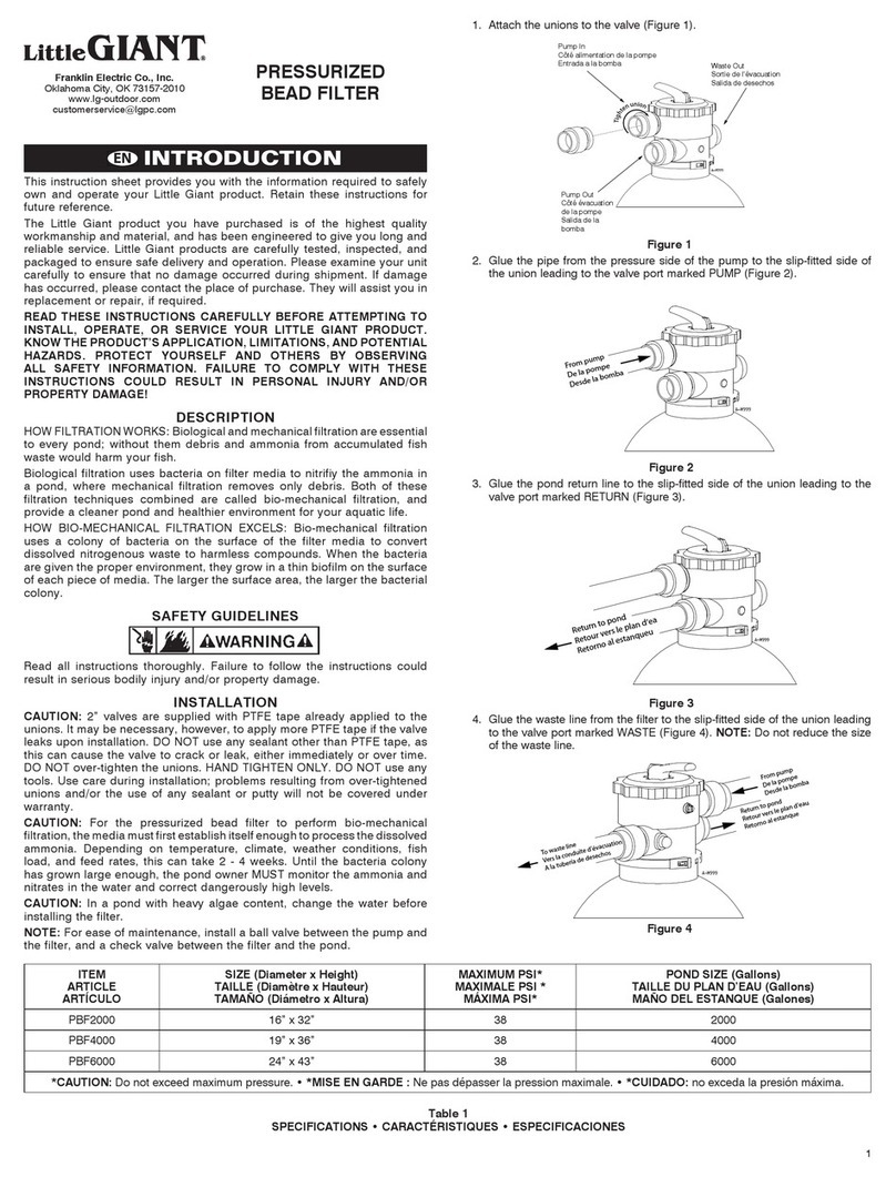
Little Giant WRS-6 User manual

BEFORE INSTALLATION:
Little Giant Wastewater Kits are carefully packaged,
inspected and tested to insure safe operation and
delivery. When you receive your unit, examine it carefully
to determine that there are no missing, broken or
damaged parts that may have occurred during shipment.
If damage has occurred, make notation and notify the firm
you purchased the unit from. They will assist you in
replacement or repair, if required. Read this manual
carefully and also the enclosed pump manual.
This unit is designed to pump wastewater from laundry
trays, washing machines, sinks or dehumidifiers. Unit is
not designed to pump raw sewage, fluids other than
water, or fluids with solids. Inlet screen will remove many
solids over 1/8" diameter, but large amounts of solids can
clog screen and result in pump failure. Maximum fluid
temperature is 125ºF. Unit is designed to fit under most
sinks so in many cases it is not necessary to recess the
unit into the floor.
ITEMS TO PURCHASE:
NOTE: Some state or local codes require all electrical
and/or plumbing connections to be made by a licensed
contractor. It is the customer’s responsibility to determine
codes involved and to comply with these codes. If user
can install unit, items to purchase are:
1. Inlet piping, with trap and union (basin cover has 11/2“
FNPT fitting).
2. Discharge piping, with swing check valve and union
(basin cover has 11/2“ FNPT fitting).
3. Vent piping (basin cover has 2" FNPT fitting).
3810 North Tulsa Street
Oklahoma City, Oklahoma 73112
(405) 947-2511
Little Pump Company
GIANT
OWNERS MANUAL
For
Little Giant®
MODEL WRS-6 WASTEWATER
REMOVAL SYSTEM WITH 6-CIA PUMP
·INSTALLATION
·OPERATION
·REPAIR PARTS
·SAFETY

SAFETY GUIDELINES
1. CAUTION: To reduce the risk of electric shock, pull
plug before servicing this pump.
2. Read all instructions and safety guidelines
thoroughly. Failure to follow the guidelines and the
instructions could result in serious bodily injury and/or
property damage.
3. Check local electrical and building codes before
installation. The installation must be in accordance
with their regulations.
4. During normal operation the pump is immersed in
water. Caution must be used to prevent bodily injury
when working near the pump:
a. The plug must be removed from the receptacle
prior to touching, servicing or repairing the pump.
b. To minimize possible fatal electrical shock hazard,
extreme care should be used when changing
fuses. Do not stand in water while changing fuses
or insert you finger into fuse socket.
ELECTRICAL CONNECTIONS
All wiring must meet local codes, and a licensed electrical
contractor is recommended. The pump is supplied with a
3-prong vented plug. Plugs must be plugged into a
grounded receptacle and vent tube must remain
unobstructed for proper pump operation. Pump should
be on a separate circuit with fuse or circuit breaker and
GFCI (ground fault circuit interrupter). Be sure electrical
supply matches pump nameplate data. Do not use
extension cord. If installed in basement, plug connection
should be 4 feet or more above floor, especially if
basement floods. Be sure electrical connections cannot
be reached by rising water. Under no circumstances
should outlet box or receptacle be located where it may
become flooded or submerged by water.
INSTALLATION
All plumbing must meet local codes. A licensed plumbing
contractor is recommended. All fixtures connected to the
WRS-6 Basin Kit must be vented according to state and
local codes.
STEP 1: Determine proper location for unit. Unit should
be located so that inlet is gravity-fed. Unit will not draw
water up from a lower level. Position and level basin. Keep
basin away from any item that could puncture basin.
Position selected should be convenient to inlet, discharge
and vent piping and electrical supply.
STEP 2: Plumb inlet. Using 1-1/2" threaded pipe, plumb
inlet to basin cover fitting. Use a P-trap and a union next to
the basin. Use pipe joint compound and hand tighten only
on plastic fittings. Do not reduce below 1-1/2" piping.
STEP 3: Plumb discharge. Using 1-1/2" threaded pipe,
plumb discharge to basin cover fitting. Use a swing
check valve no more than 3" from top of basin cover
and a union. Be sure check valve is installed in proper
flow direction.
If check valve is installed backwards, no water will flow
out of unit. Be sure discharge piping is sealed with pipe
joint compound and that lift height of pump is not
exceeded. Hand tighten only on plastic fittings.
STEP 4: Plumb vent. Plumb vent using 2" threaded
pipe to fitting in basin cover. Use pipe joint compound
on threads and hand tighten only on plastic fittings.
The basin must be vented in accordance with state and
local codes. The vent is essential for proper switch
operation and must not be omitted or restricted.
CAUTION: Do not use a mechanical vent with this
product. A mechanical vent will cause improper
operation of the automatic switch.
STEP 5: Test Unit. Connect power cord to electrical
supply as stated under “Electrical Connections.”
Secure power cord to piping with ties or tape. Fill unit
with water through inlet. Pump should turn on with
7"–10" of water in tank, and turn off when 1"–3" of water
is left in tank.
MAINTENANCE
Maintenance operations consist of cleaning basin inlet
screen in cover, cleaning basin and limited pump
maintenance. WARNING: Before any maintenance is
performed, shut off water inlet and disconnect power cord
from supply outlet. Pump may become hot in operation.
Allow pump to cool before servicing.
Basin Screen – Remove (4) 1/4-20 screen cover plate
screws, plastic cover plate, o-ring and screen. Clean inlet
screen using a mild detergent and water. Examine o-ring
and if deformed, replace with new o-ring. See
replacement parts list.
Basin – Sediment may build up in basin causing pump to
operate improperly. Remove (10) 1/4-20 screws from
cover. Remove cord grommet and loosen cords to allow
slack and then remove cover.
Remove pump and clean basin using a mild detergent
and water. Reassemble in reverse order.
Torque screws 18-20 in.-lbs.
If pump alignment plate is removed, it must be reinstalled
per pump alignment diagram.
Pump – Sediment or lint can clog pump and cause
improper operation. If necessary, remove pump and
pull off the pressed-in screen. Clean using a mild
detergent and water and reinstall. Plastic pump base
may also be removed to clean around impeller and
inside base. Remove the 6 base screws and clean base
using a mild detergent and water. Do not remove
impeller. When reinstalling base, be sure seal ring is
seated properly in groove and torque screws to 10-15
in.-lbs. See pump manual for other information. For
any other pump repair, return the pump to a Little Giant
authorized service center.

TYPICAL INSTALLATION
FOR TROUBLE-SHOOTING INFORMATION
SEE PUMP OWNERS MANUAL INCLUDED WITH
WRS-6 BASIN KIT.
SPECIFICATIONS
MODEL
NUMBER VOLTS HERTZ AMPS WATTS GALLONS PER HOUR (GPH) AT HT. SHUTOFF
(FT.)
MAX.
PSI
5’ 10’ 15’
WRS-6 115 60 9 720 2750 1750 750 18 7.8
8 FT. POWER CORD
(CORD GROMMET INCULDED)
*2" VENT PIPE
FILTER ACCESS COVER
WITH O-RING
FILTER
*UNION
*1-1/2" INTAKE
COVER O-RING
14.50"
*- ITEMS NOT INCLUDED WITH WRS-6 BASIN KIT
*1-1/2" CHECK VALVE
*1-1/2" UNION
*1-1/2" DISCHARGE PIPE
BASIN COVER
BASIN
1-1/2" DISCHARGE PIPE
LITTLE GIANT PUMP
MODEL 6-CIA
15.56"
10.63" DIA.
13.88" DIA.

REPLACEMEMT PARTS LIST
ITEM PART # DESCRIPTION QTY.
1 113130 BASIN COVER 1
2 901709 SCREW, 1/4"-20 X 1/2" 14
3 924125 O-RING, 11.975 I.D. 1
4 113129 BASIN 1
5 113140 DISCHARGE PIPE 1
6 506158 PUMP, 6-CIA, 115V 1
7 925016 CORD GROMMET 1
8 113131 INTAKE SCREEN 1
9 924126 O-RING, 3.225 I.D. 1
10 113132 COVER PLATE, SCREEN 1
11 113135 ALIGNMENT PLATE 1
ONE YEAR LIMITED WARRANTY
For one year from date of purchase, Little Giant
Pump Company will repair this unit if defective in
material or workmanship. Warranty service is
available by returning the unit prepaid to the factory.
For further details, please consult the warranty
statement on carton. This warranty gives you
specific legal rights and you may also have other
rights which vary from state to state.
KEEP THIS FOLDER
File this for safekeeping. It may be valuable to your for service under the terms of the warranty.
Date of Purchase ___________________________ Name of Dealer __________________________________________________
Serial #______________________ Product # _____________________________ Model # _______________________________
©Copyright 2001 Little Giant Pump CompanyFORM 993801 — 04/24/2001:
Printed by Little Giant DocServ
Other manuals for WRS-6
3
Other Little Giant Water Filtration System manuals
Popular Water Filtration System manuals by other brands

Atlantic Ultraviolet
Atlantic Ultraviolet Mighty Pure MP16A owner's manual

SunSun
SunSun CBG-500 Operation manual

Hayward
Hayward XStream Filtration Series owner's manual

Contech
Contech DownSpout StormFilter Operation and maintenance

Teka
Teka Airfilter MINI operating instructions

Wisy
Wisy LineAir 100 Installation and operating instructions

Schaffner
Schaffner Ecosine FN3446 Series User and installation manual

Pentair
Pentair FLECK 4600 SXT Installer manual

H2O International
H2O International H20-500 product manual

Renkforce
Renkforce 2306241 operating instructions

Neo-Pure
Neo-Pure TL3-A502 manual

STA-RITE
STA-RITE VERTICAL GRID DE FILTERS S7D75 owner's manual


