Little Machine Shop HiTorque 3990 User manual

HiTorque™
Mini Mill Users Guide
Model 3990 • Model 4190 Deluxe • Model 6450 Deluxe, Mirror Display
from LittleMachineShop.com®

Updated 4/21/2023 © 2023 LittleMachineShop.com Page 2of 54
© Copyright 2023 LittleMachineShop.com®
All rights reserved.
Written by Chris Wood of LittleMachineShop.com®
Version 1, April 2023
LittleMachineShop.com®
https://www.littlemachineshop.com
396 W. Washington Blvd. #500, Pasadena, CA 91103
(800) 981-9663

Updated 4/21/2023 © 2023 LittleMachineShop.com Page 3of 54
Contents
Introduction ................................................................................................5
Specifications...............................................................................................5
Safety Considerations .....................................................................................6
General Safety...........................................................................................6
Milling Machine Safety..................................................................................6
Electrical Safety.........................................................................................6
Machine Safety ..........................................................................................7
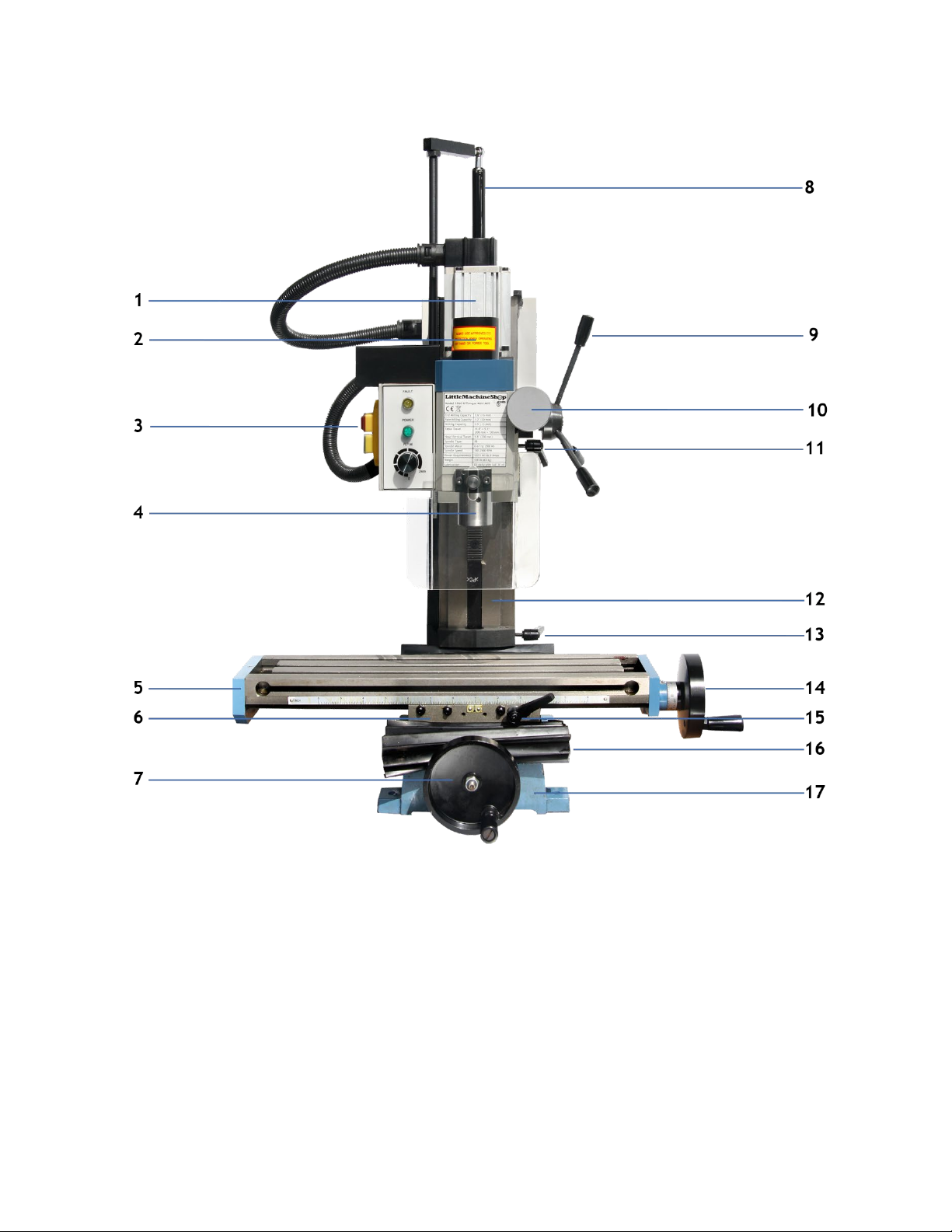
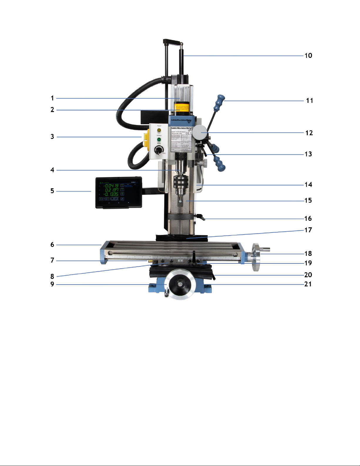
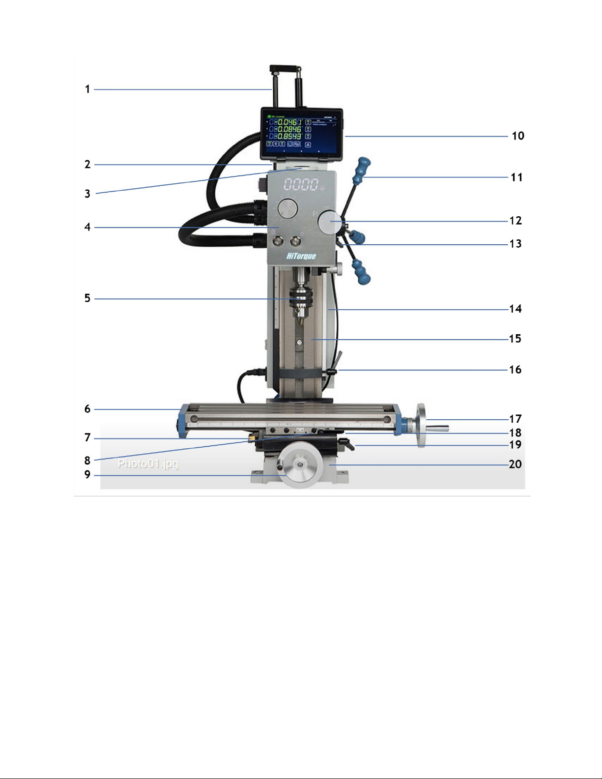
Features .....................................................................................................8
Basic Accessories......................................................................................... 11
Cleaning ................................................................................................... 11
Assembly .................................................................................................. 11
Mounting Your Mill ....................................................................................... 12
Operating Controls....................................................................................... 13
Motor Controls ......................................................................................... 13
Using the Motor Controls............................................................................. 15
X-Axis Hand Wheel .................................................................................... 16
X-Axis Lock Lever ..................................................................................... 16
Y-Axis Hand Wheel .................................................................................... 16
Y-Axis Lock Lever ..................................................................................... 17
Z-Axis Coarse Feed Handles ......................................................................... 17
Z-Axis Fine Feed Knob ................................................................................ 17
Z-Axis Lock Lever...................................................................................... 17
Bluetooth DRO (Models 4190 & 6450) ................................................................. 18
Using the app .......................................................................................... 19
Axis detail settings.................................................................................... 20
Absolute vs incremental coordinates............................................................... 20
Points and workspaces ............................................................................... 21
Tools .................................................................................................... 21
Starting a work piece................................................................................. 22
Centering a work piece............................................................................... 22
Adjustments .............................................................................................. 24
X-Axis Gib .............................................................................................. 24
Y-Axis Gib .............................................................................................. 25
Z-Axis Gib .............................................................................................. 25
Tramming the Mill..................................................................................... 25
Lubrication................................................................................................ 27

Updated 4/21/2023 © 2023 LittleMachineShop.com Page 4of 54
Maintenance .............................................................................................. 28
Cleaning ................................................................................................ 28
Changing Spindle Tools.................................................................................. 28
Squaring a Vise ........................................................................................... 31
Using Parallels............................................................................................ 32
Clamping with a Clamping Kit.......................................................................... 32
Finding the Edge of a Workpiece ...................................................................... 33
Drilling..................................................................................................... 34
Milling ..................................................................................................... 35
Conventional Milling Versus Climb Milling............................................................ 36
Plunge Milling............................................................................................. 36
Milling Slots ............................................................................................... 37
Surfacing .................................................................................................. 37
Common Accessories .................................................................................... 37
End Mills ................................................................................................ 38
Work Holding........................................................................................... 39
Vises..................................................................................................... 39
Clamping Kits and Accessories ...................................................................... 39
Setup Tools............................................................................................. 40
Parts Diagrams ........................................................................................... 41
Parts List .................................................................................................. 46
Wiring Diagrams.......................................................................................... 53

Updated 4/21/2023 © 2023 LittleMachineShop.com Page 5of 54
Introduction
This user’s guide covers operation and care of the LittleMachineShop.com HiTorque Mini Mill.
Be sure to read and understand the safety guidelines presented in this book before using
your HiTorque Mini Mill.
Specifications
End Milling Capacity 0.6" (16 mm)
Face Milling Capacity 1.2" (30 mm)
Drilling Capacity 0.5" (13 mm)
Table Size 18.1" x 4.7" (460 mm x 120 mm)
T-slots 3 slots 0.47" (12.0 mm) wide
X-Axis Travel 11.8" (300 mm)
Y-Axis Travel 5.1" (130 mm)
Z-Axis Travel 10.6" (270 mm)
Throat 6.5" (165 mm)
X- and Y-Axis Feed Screws 0.0625" (1.59 mm) per rotation
Positioning Accuracy 0.0004" (0.010 mm)
Spindle Taper R8
Spindle Motor 0.67 hp (500 Watts)
Spindle Speed 100 - 2500 RPM ±10%
Power Requirements 120 V 60 Hz 8 Amps
Machine Weight 3990/4190 124 lbs (57 kg)
Overall Dimensions (W x D x H)
3990/4190
23.2" x 19.7" x 35.4" (590 mm x 500 mm x 900 mm)
Machine Weight 6450 187 lbs (85 kg)
Overall Dimensions (W x D x H)
6450
23.2" x 19.7" x 36.3" (590 mm x 500 mm x 922 mm)

Updated 4/21/2023 © 2023 LittleMachineShop.com Page 6of 54
Safety Considerations
Always use common sense when using a power tool. Review the following safety instructions.
Besides the general safety rules for any power tool, the following include specific
considerations for the mini mill.
General Safety
•Use common sense. Think through the results of your actions before you act.
•Understand the operation of the machine. Do not operate the machine if you do not know
what is going to happen.
•Learn, don't experiment. Study, understand, and do things where you have a clear
expectation of the outcome. Don't “see what will happen.”
•You are responsible for your own actions. We can't be held responsible for your actions when
you use the machine.
Milling Machine Safety
•Your mini mill is just that, a mini, or small mill. Don’t attempt jobs that are beyond its
capacity.
•Check the workpiece after you secure it in the vise or other work holding device. Be sure it is
secure before turning on the mill.
•Don’t wear loose clothing or jewelry when operating the mill.
•Stop the spindle and make sure the machine is in a safe condition before:
oOpening or removing safety shields
oReaching into work area
oChanging or adjusting tools
oChanging or adjusting workpieces
oChanging speed ranges
oClearing chips or coolant
•Inspect cutting tools for sharpness, chips, and cracks before each use. Replace dull, chipped,
or cracked cutting tools immediately.
•Handle cutting tools with care. Cutting edges are very sharp and can cause lacerations.
•Do not use unbalanced tools or fixtures in the spindle
•Remove all tools (wrenches, chuck keys, locking pins, and so on) from the spindle
immediately after using them.
Electrical Safety
•Plug the machine into a grounded, ground fault protected receptacle.
•Ensure that all components are properly grounded. The easiest way to ensure this is to plug
your machines and devices into grounded outlets that you have tested.
•Use caution when using liquids and electricity. Ensure that coolants and lubricants are kept
away from high voltage electrical components.
•Disconnect all components from the power receptacle before servicing.

Updated 4/21/2023 © 2023 LittleMachineShop.com Page 7of 54
•In the event of a power outage, turn off all components to ensure that the machine does not
restart unexpectedly.
Machine Safety
•Keep bystanders, children, and visitors a safe distance away while operating any power tool.
•Read the manual. Know the operation of every control before you attempt any operation of
the machine.
•Make sure that all guards are in place and functioning before operating the machine.
•Check for damage and abnormal wear before operating the machine.
•Always wear safety glasses (side shields are recommended) that are ANSI Z87.1-2003
compliant.
•Wear hearing protection (ear plugs or ear muffs) when operating loud machines.
•Wear appropriate clothing; no rings, gloves, neckties, jewelry, or loose-fitting garments.
Bind long hair or wear a hat.
•Do not use compressed air for cleaning machines. A shop vacuum works well and is much
safer.
•Don't operate machinery while under the influence of drugs or alcohol.
•Ensure that your machines are well lit. Ensure that your shop is well lit, and have additional
task lighting where appropriate.
•Maintain a clean and uncluttered work area.
•Avoid pinch points.
•Never leave a running machine unattended.
•Do not force or overload machinery.
•Use appropriate cutting tools with appropriate feeds and speed.
•Cutting tools get hot during use and can cause burns if handled inappropriately.
•Do not attempt to use workpieces that are too large or two heavy for the machine.
•Maintain your machines. Ensure that it is well-adjusted and in a safe state.
•Clear chips with a brush or other tool, never with your hands or with compressed air.
•Make sure the machine is on a flat, level surface that is capable of supporting the weight of
the machine plus fixtures, vise, and workpiece.
•Clamp work securely. Cutting forces are significant and can turn workpieces that are not
secured into projectiles.
•Be aware that chips and dust from some materials (magnesium, for example) are flammable.
Understand the materials you are using.

Updated 4/21/2023 © 2023 LittleMachineShop.com Page 8of 54
Features
Model 3990 Shown
1. Motor
2. Drawbar (under cap)
3. Motor controls
4. Spindle
5. Table
6. Saddle
7. Y-axis hand wheel
8. Air Spring
9. Z-axis coarse feed handle
10. Z-axis fine feed knob
11. Z-axis lock lever
12. Column
13. Z-axis travel stop
14. X-axis hand wheel
15. X-axis lock lever
16. Y-axis lock lever
17. Base

Updated 4/21/2023 © 2023 LittleMachineShop.com Page 9of 54
Model 4190 Shown
1. Motor
2. Drawbar (under cap)
3. Motor controls
4. Spindle
5. DRO Tablet
6. Table
7. Y-axis DRO Scale & Reader
8. Saddle
9. Y-axis hand wheel
10. Air Spring
11. Z-axis coarse feed handle
12. Z-axis fine feed knob
13. Z-axis lock lever
14. Z-axis DRO Scale & Reader
15. Column
16. Z-axis travel stop
17. X-axis DRO Scale & Reader
18. X-axis hand wheel
19. X-axis lock lever
20. Y-axis lock lever
21.Base

Updated 4/21/2023 © 2023 LittleMachineShop.com Page 10 of 54
Model 6450 Shown
1. Air Spring
2. Motor
3. Drawbar (under cap)
4. Motor controls
5. Spindle
6. Table
7. Y-axis DRO Scale & Reader
8. Saddle
9. Y-axis hand wheel
10. DRO Tablet
11.Z-axis coarse feed
handle
12.Z-axis fine feed knob
13.Z-axis lock lever
14.Z-axis DRO Scale & Reader
15.Column
16.Z-axis travel stop
17.X-axis hand wheel
18.X-axis lock lever
19.Y-axis lock lever
20.Base

Updated 4/21/2023 © 2023 LittleMachineShop.com Page 11 of 54
Basic Accessories
The following accessories come with the HiTorque Mini Mill.
•Mini Mill Users Guide
•2 T-slot nuts with 3/8"-16 thread
•Three open end wrenches (8/10 mm,
14/17 mm, 17/19 mm)
•Four hex (Allen) wrenches (3, 4, 5, and 6
mm)
•One 45-52 mm spanner wrench
•Spindle lock pin
•One 1/2" drill chuck and R8/JT33 arbor
•Oil can (plastic)
•7" Android tablet for DRO display (Models 4190 & 6450)
•T-type socket wrench for drawbar (Model 6450)
Cleaning
Your mill will arrive coated with grease to protect it from corrosion during shipment. Follow
this procedure to remove the grease:
1. Wipe most of the grease off with rags or paper towels.
2. Clean the surfaces with mineral spirits (paint thinner).
3. Coat the surfaces with oil.
See the “Lubrication” section on page 27 for specific recommendations for lubricants.
Assembly
There is only one thing to do to assemble your mill. Install the handles on the X- and Y-axis
hand wheels. The handles should turn freely when installed.

Updated 4/21/2023 © 2023 LittleMachineShop.com Page 12 of 54
Mounting Your Mill
The mini mill must be bolted down to the workbench because it is top-heavy. It is unsafe to
operate the mini mill if it is not bolted to a workbench.
Before you mount your mini mill, plan the positioning carefully. If you simply bolt it to the
middle of the workbench, you won’t be able to turn the Y-axis hand wheel. Either mount the
mini mill at the front edge of the bench so the Y-axis hand wheel hangs over the edge of the
bench, or mount the mini mill on a riser about 1.5" thick to provide room to turn the Y-axis
hand wheel. The mounting bolts must extend through the riser and bolt the mill to the
bench to keep it from tipping.
Be sure that you have room on both sides of the mill for the X-axis travel. The table will
move to the right so that the left end of the table is almost flush with the saddle. You need
an additional 8" to the right so that you can remove the table off the right side of the mill.
The table moves to the left so that the right end of the table is almost flush with the saddle.
The following diagram shows the holes required to mount the mill and the clear area around
the bolt pattern to allow use and maintenance of the mini mill.
Mount the mill to the workbench with 3/8" or 10 mm bolts. The bolts should be about 1" (25
mm) longer than the thickness of the workbench. Use fender washers on the underside of
wooden benches to prevent the nuts from pulling through.

Updated 4/21/2023 © 2023 LittleMachineShop.com Page 13 of 54
Operating Controls
There are several controls used to operate the mill. Become familiar with them before you
use the mill.
Motor Controls
3990 / 4190 Controls
1. Power and emergency stop (E-stop) switch
2. Speed control
Power Switch and Emergency Stop (E-stop) Switch
The green power switch enables input power to the speed control circuit board. The red E-
stop switch disconnects the power.
Turn the power off when you are not using the lathe.
Speed Control Knob
You control the motor speed by adjusting a potentiometer that provides the speed setting
value to the speed control circuit board.

Updated 4/21/2023 © 2023 LittleMachineShop.com Page 14 of 54
6450 Controls
1. Power switch & Emergency stop (E-stop) switch
2. Spindle speed readout
3. Speed control knob
4. Z-axis fine feed knob
5. Spindle direction button
6. Start/stop button
Power Switch and Emergency Stop (E-stop) Switch
The green power switch enables input power to the speed control circuit board. The red E-
stop switch disconnects the power.
Turn the power off when you are not using the lathe.
Spindle Speed Readout
The spindle speed readout shows the speed of the spindle in revolutions per minute (RPM). It
also indicates the direction of turning, forward or reverse.
Speed Control Knob
The speed control knob adjusts the spindle speed.

Updated 4/21/2023 © 2023 LittleMachineShop.com Page 15 of 54
Z-axis fine feed knob
See Z-Axis Fine Feed Knob on page 17.
Spindle Direction Button
The spindle direction button controls the direction the spindle turns. After turning on the
power and pressing start, the spindle turns in the forward direction - the direction used for
normal turning. Press the button to toggle between forward and reverse directions. The
button illuminates to indicate reverse direction.
You can change the motor direction at any time and at any speed that safety allows. The
motor will make a controlled change of direction.
Start/Stop Button
The Start/Stop button illuminates and starts the spindle when pressed while the power is on.
The spindle runs at the last set speed. Press the button again to stop the spindle. Use this
button for normal operation of the lathe.
Using the Motor Controls
Use the motor controls to turn the spindle.
Models 3990 & 4190
To power up the mill:
1. Turn the speed control to the minimum speed position.
2. Turn on the power switch by pressing the green button.
Always turn the power off when you leave the mill. Leaving the power on can damage the
speed control circuit board.
To power down the mill:
1. Turn the speed control to the minimum speed position.
2. Turn off the power by pushing the red button.
To start the mill:
1. Ensure that the speed control is set to the minimum speed position.
2. Advance the speed control to the desired speed.
To stop the mill:
•Turn the speed control to the minimum speed position.
Model 6450
To power up and start the lathe:
3. Turn on the power switch by pressing the green button. The control panel LED displays
will illuminate.
4. If you do not remember your previous turning speed or want to begin turning at the
minimum speed, turn the speed dial counterclockwise to the lowest RPM.

Updated 4/21/2023 © 2023 LittleMachineShop.com Page 16 of 54
5. Press the start/stop button to begin the spindle turning. The spindle will begin rotating
at the last speed set on the speed dial when the lathe was turned off or the start/stop
button was disengaged. The start/stop button will illuminate when engaged.
6. Adjust the spindle speed dial to the desired RPM.
7. If you wish to change the spindle direction, press the spindle direction button. The
spindle will briefly stop its rotation and then change direction at the same speed it was
spinning before the direction change. The spindle direction button will illuminate when
engaged.
8. Adjust the speed control as necessary.
To stop the lathe:
9. If you do not wish your next operation to begin at the current spindle speed, turn the
speed control down to the minimum speed.
10.If the spindle is in the reverse rotation press the spindle direction button. The spindle
will momentarily stop and begin spinning in the forward rotation.
11.Press the start/stop button. The spindle will stop rotating.
12.If you want to power down the lathe, press the red button to turn off the power. The LED
control illumination will turn off.
X-Axis Hand Wheel
The X-axis hand wheel moves the table to the left or right, depending on which way it is
turned. Use this hand wheel to position the table.
The dial on this handle indicates the relative position of the table. The graduated dial can
be repositioned for convenience. Each division of the dial represents a movement of 0.001".
The HiTorque Mini Mill has 62.5 graduations on the dial. Each full turn of the hand wheel
moves the table 0.0625" (1/16").
X-Axis Lock Lever
The X-axis lock lever is on the front of the saddle behind the Y-axis hand wheel. Use this
lever to lock the X-axis so it does not move inadvertently.
Pulling out on the lever and simultaneously turning it can change the locked position of this
lever. Pulling out disengages the lever from the locking screw and allows it to move to a
different position. You might need to adjust the screw in the base of the lever before you
can disengage the lever.
Y-Axis Hand Wheel
The Y-axis hand wheel moves the table to the front or back, depending on which way it is
turned. Use this hand wheel to position the table.
The dial on this handle indicates the relative position of the table. The graduated dial can
be repositioned for convenience. Each division of the dial represents a movement of 0.001".
The HiTorque Mini Mill has 62.5 graduations on the dial. Each full turn of the hand wheel
moves the table 0.0625" (1/16").

Updated 4/21/2023 © 2023 LittleMachineShop.com Page 17 of 54
Y-Axis Lock Lever
The Y-axis lock lever is on the right side of the saddle behind the X-axis hand wheel. Use this
lever to lock the Y-axis so it does not move inadvertently.
Pulling out on the lever and simultaneously turning it can change the locked position of this
lever. Pulling out disengages the lever from the locking screw and allows it to move to a
different position. You might need to adjust the screw in the base of the lever to make this
adjustment.
Z-Axis Coarse Feed Handles
The Z-axis coarse feed handles are on the right side of the spindle housing. The three long
handles allow you to quickly lower and raise the head. Use them to position the mill head,
and also for drilling.
Z-Axis Fine Feed Knob
The Z-axis fine feed knob is located on the right front corner of the spindle housing. Use this
knob to make find adjustments to the position of the head assembly.
There are 60 divisions on the dial. Each full turn of the knob moves the head assembly
0.060". Each division of the dial represents a movement of 0.001".
To engage the Z-axis fine feed:
•Move the hub and coarse feed handles in to engage the dog clutch. You might need to turn
the Z-axis fine feed knob to align the dogs.
To disengage the Z-axis fine feed:
•Move the hub and coarse feed handles out to disengage the dog clutch. You might need to
turn the Z-axis fine feed knob to relieve pressure from the dogs.
Fine feed disengaged
Fine feed engaged
Z-Axis Lock Lever
The Z-axis lock lever is on the right side of the head assembly behind the Z-axis coarse feed
hub. Use this lever to lock the Z-axis so it does not move inadvertently.
Pulling out on the lever and simultaneously turning it can change the locked position of this
lever. Pulling out disengages the lever from the locking screw and allows it to move to a

Updated 4/21/2023 © 2023 LittleMachineShop.com Page 18 of 54
different position. You might need to adjust the screw in the base of the lever to make this
adjustment.
Bluetooth DRO (Models 4190 & 6450)
The Android tablet included with your DRO has the SIEG DRO app preinstalled. To begin using
it, you must pair the tablet to the DRO scales, and you must configure the app, as described
in the following sections.
To pair the devices
Be sure the Bluetooth transceiver is plugged in. (If you have the 4190 Deluxe Mini Mill, the
transceiver is plugged in when the machine is plugged in.) Follow these steps to pair the
Bluetooth transceiver with your Android tablet.
On the Android tablet:
1. Turn on the power and swipe up to unlock it.
2. Open Settings. (If you don’t see a Settings icon near the center of the screen, open the
app drawer—the middle icon of the quick launch bar on the bottom or right edge of the
screen.)
3. In Settings, tap Bluetooth under Wireless & Networks.
4. Tap Search For Devices in the upper right corner of the screen.
5. Tap HC-06 when it appears under Available Devices.
6. Enter the PIN 1234 and tap OK.
The devices are now paired.
Chris’ Tip: If you’re using a single display device for multiple DROs, you can change the
name from HC-06 to give each machine a unique name. Tap a name under Paired Devices,
edit the name, and tap OK.
To configure the app:
1. Start the SIEG DRO app.
2. If it appears in the upper-right corner of the screen, tap Connect to select the correct
Bluetooth device. Tap HC-06 to select the mill.
3. The vertical ellipsis in the upper right corner of the screen is a menu. Tap it and select
Settings.
4. Here is where you tell the app about your machine. Verify the following settings.
•Machine type: Mill
•Under X Axis
°Axis CPI: 5080
°Invert Readout: check
•Under Y Axis
°Enable Y Axis: remove check
•Under Z Axis

Updated 4/21/2023 © 2023 LittleMachineShop.com Page 19 of 54
°Axis CPI: 5080
•Under W Axis
°Enable W Axis: remove check
5. Tap the Back button at the bottom of the screen when you have made the settings.
Using the app
Your DRO should now be working. Turn a hand wheel and watch the numbers change.
The axis readouts appear at the left top of the screen.
The row of buttons across the bottom affect all axes.
The row of abs/incr buttons to the right of each axis readout affect that axis.
The right side of the screen is for more advanced functions.
Chooses inch or mm display
Sets the workspace origin to the current position of the
machine
Selects Absolute coordinates or Incremental coordinates
for all axes
Creates circular bolt patterns
Creates rectangular bolt patterns
Specifies tool offsets

Updated 4/21/2023 © 2023 LittleMachineShop.com Page 20 of 54
Axis detail settings
Tap one of the axis position values to see the Axis Details.
Tap the Position value to enter the current position value.
Reduces the position value to half its value. Use this for centering.
If you are viewing an absolute value, it stores half the absolute value in the
incremental value.
If you are viewing an incremental value, it halves the incremental value.
Changes the sign of the position value and changes the “positive” direction of that
axis.
Tap to set the incremental value to zero.
Hold to set both the absolute value and the incremental value to zero.
Turns on the warning that you are approaching a defined point.
Absolute vs incremental coordinates
The DRO keeps track of two coordinate systems: absolute and incremental.
Absolute coordinates are the overall coordinates of your work piece. Select a corner of the
workpiece and use your edge finder to set the X- and Y-axes to 0.000 at this corner.
Incremental coordinates are used when you want to work on a feature, such as a bolt circle,
that exists on your work piece. You can, for example, set an incremental 0, 0 position at the
center of a circular bolt circle, and then use incremental values to place the holes.
This manual suits for next models
2
Table of contents
Popular Industrial Equipment manuals by other brands

ABB
ABB E-kit installation instructions

Bühler technologies
Bühler technologies GAS 222.30 Assembly, installation and operation instructions

Schmalz
Schmalz SPZ operating manual

Bosch
Bosch Rexroth HAD 1 Series operating instructions

Grundfos
Grundfos SQ Service instructions

Siemens
Siemens Sivacon S8 operating instructions

Viking
Viking VFT Installation, operation and maintenance manual

Precision
Precision X40 MSE Operational manual

Sullair
Sullair 65 II Use and Maintenance Spare Parts List

KTR-Group
KTR-Group REVOLEX KX Series Operating & assembly instructions

APEX DYNAMICS
APEX DYNAMICS P Series user manual

Jäger
Jäger Z33-D060.52 S21 manual