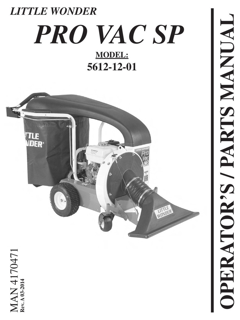
Little Wonder 5612-00-59 User manual

SET-UP / PARTS MANUAL
LITTLE WONDER
HPV
High Performance Vac
MODEL:
5612-00-59
MAN 4167416
Rev. A 12-2011
Original Language Instructions
Operators Manual 4167415

CALIFORNIA
Proposition 65 Warning
Diesel engine exhaust and some
of its constituents are known to the
State of California to cause cancer,
birth defects and other reproductive
harm.
WARNING
The engine exhaust from this product
containschemicalsknowntotheState
of California to cause cancer, birth
defects or other reproductive harm.
CALIFORNIA
Proposition 65 Warning
Battery posts, terminals, wiring
insulation, and related accessories
contain lead and lead compounds,
chemicals known to the State of
California to cause cancer and birth
defects or other reproductive harm.
WASH HANDS AFTER HANDLING.

3
LITTLE
WONDER
HPV VAC
IMPORTANT MESSAGE
On behalf of everyone at Little Wonder, we would like to thank you for your purchase of a Little Wonder High
Powered Vacuum This professional vac was designed to the highest standards to ensure you many hours of
uninterrupted service.
This manual provides the information necessary for safe and efcient operation and service. For your safety, it
is critically important that you read and understand this entire manual before operating your blower.
LITTLE WONDER
SCHILLER GROUNDS CARE, INC.
1028 STREET ROAD, P.O. BOX 38
SOUTHAMPTON, PA 18966
12-2011
TABLE OF CONTENTS FIGURES PAGE
SAFETY........................................................................................................................................................4, 5
LABELS........................................................................................................................................................6, 7
SET-UP INSTRUCTIONS.............................................................................................................................8, 9
FAN REMOVAL ..............................................................................................................................................10
PARTS SECTION...........................................................................................................................................11
PARTS ASSEMBLY..................................................................................................................................12, 13
COLLECTOR ASSEMBLY........................................................................................................................14, 15
LINER ASSEMBLY ...................................................................................................................................16, 17
NOZZLE ASSEMBLY ...............................................................................................................................18, 19
WARRANTY ............................................................................................................................... BACK COVER

4
LITTLE
WONDER
HPV VAC
SAFETY
NOTICE !!!
Unauthorized modications may present extreme
safety hazards to operators and bystanders and
could also result in product damage.
Schiller Grounds Care, Inc. strongly warns against,
rejects and disclaims any modications, add-on
accessories or product alterations that are not
designed,developed,testedandapprovedbySchiller
Grounds Care, Inc. Engineering Department. Any
Schiller Grounds Care, Inc. product that is altered,
modied or changed in any manner not specically
authorized after original manufacture-including the
additionof“after-market”accessoriesorcomponent
parts not specically approved by Schiller Grounds
Care, Inc.-will result in the Schiller Grounds Care,
Inc. Warranty being voided.
Any and all liability for personal injury and/or
property damage caused by any unauthorized
modications, add-on accessories or products not
approved by Schiller Grounds Care, Inc. will be
considered the responsibility of the individual(s) or
company designing and/or making such changes.
Schiller Grounds Care, Inc. will vigorously pursue
full indemnification and costs from any party
responsible for such unauthorized post-manufacture
modications and/or accessories should personal
injury and/or property damage result.
This symbol means:
ATTENTION!
BECOME ALERT!
Your safety and the safety of others is involved.
Signal word denitions:
The signal words below are used to identify levels
of hazard seriousness. These words appear in this
manualandonthesafetylabelsattachedtoSchiller
Grounds Care, Inc. machines. For your safety and
thesafetyofothers,readand followtheinformation
given with these signal words and/or the symbol
shown above.
DANGER indicates an imminently hazardous
situationwhich, ifnot avoided,WILLresult indeath
or serious injury.
WARNING indicates a potentially hazardous
situation which, if not avoided, COULD result in
death or serious injury.
CAUTION indicates a potentially hazardous situation
which,ifnotavoided,MAY resultinminorormoderate
injury. It may also be used to alert against unsafe
practices or property damage.
CAUTION used without the safety alert symbol
indicates a potentially hazardous situation which, if
not avoided, MAY result in property damage.
MODEL NUMBER: This number appears on
sales literature, technical manuals and price lists.
SERIAL NUMBER: This number appears only
on your unit. It contains the model number fol-
lowed consecutively by the serial number. Use
this number when ordering parts or seeking war-
ranty information.

5
LITTLE
WONDER
HPV VAC
SAFETY
Fuel
- Petrol (gasoline) and diesel
fuels are ammable; petrol
(gasoline) vapors are explo-
sive. Use extra care when
handling.
- Store only in containers
specically designed for fuel.
MAINTENANCE SAFETY
In general
- Maintain machine according to manufacturer's sched-
ule and instructions for maximum safety and best
results.
- Park machine on level ground.
- Never allow untrained personnel to service machine.
- Guards should only be removed by a qualied techni-
cian for maintenance or service.
- Adjust or repair only after the engine has been
stopped and the fan has stopped moving.
- Disconnect spark plug wire(s) before doing any main-
tenance.
- Replace parts if worn, damaged or faulty. For best
results, always replace with parts recommended by
the manufacturer.
- Do not dismantle the machine without releasing or
restraining forces which may cause parts to move
suddenly.
- Provide adequate support, e.g. jack stands for lifted
machine or parts if working beneath.
- Do not put hands or feet near or under rotating parts.
- Clean up spilled oil or fuel thoroughly.
- Replace faulty mufers.
- To reduce re hazards, keep the engine, mufer, and
fuel storage area free of grass, leaves, debris buildup
or grease.
WARNING
Fans
Do not straighten or weld fans. Replace damaged or
failed fans.
- When refueling or checking fuel level:
- Stop the engine and allow to cool;
- Do not smoke;
- Refuel outdoors only;
- Use a funnel;
- Do not overll;
- If fuel is spilled, do not attempt to start the en-
gine until the spill is cleaned up and vapors have
cleared.
- Replace caps on fuel containers and tanks secure-
ly.
Sparks from static electricity can start res or cause
explosions. Flowing fuel can generate static electricity.
To prevent static electricity sparks:
- Keep containers electrically grounded. Do not ll
containers in a vehicle or on a truck or trailer bed
with a plastic liner. Fill containers on the ground
away from the vehicle.
- When practical, remove petrol (gasoline) powered
equipment from the truck or trailer and refuel it on the
ground. If equipment must be refueled on the truck
or trailer, refuel from a portable container rather than
a dispenser nozzle.
- Keep the dispenser nozzle in contact with the rim
of the fuel tank or container opening until fueling is
complete. Do not use a nozzle lock-open device.
- If petrol (fuel) is spilled on clothing change it
immediately.
STORAGE SAFETY
- Stop the engine and allow to cool before storing.
- Drain the fuel tank outdoors only.
- Store fuel in an approved container in a cool, dry
place.
- Keep the machine and fuel containers in a locked stor-
age place to prevent tampering and to keep children
from playing with them.
- Donotstorethemachineorfuelcontainernearanopen
ame, spark, or appliance, such as a water heater, or
a pilot light.
- Keep petrol (gasoline) storage area free of grass,
leaves and excessive grease to reduce re hazard.
- Clean grass and debris from cutting units, drives,
mufers and engine to help prevent res.

6
LITTLE
WONDER
HPV VAC
LABELS
4167414
SAFETY DECALS
An important part of the safety system incorporated in this blower are the warning labels found on the blower.
Replace labels if damaged or illegible.
<
<
<
<
Wear eye and ear
protection.
Wear Respiratory
Equipment to protect
yourself from breathing
dust.
Keep bystanders away.
Caution:
Thrown objects.
Keep bystanders away.
Do not blow towards
people or items that may
be injured or damaged by
ying debris.
Before performing
any service or
maintenance,
disconnect spark
plug wire. Make sure
engine switch is in the
OFF (O) position.
Read and understand
the operator manual.
Pay particular attention
to all sections regard-
ing safety. Store your
owners manual in a
safe place.
Caution:
Contact with rotating
fan will cause serious
injury. Keep hands
away from air intake
and discharge areas.
<

7
LITTLE
WONDER
HPV VAC
LABELS
Thrown Object / Flying Debris Hazard
-Do not operate without properly attached bag.
-Stop engine before removing bag.
4165567
STOP
4165566
Rotating Blades:
CUT / AMPUTATION HAZARD
-Keep hands out of fan housing.
-Stop engine and remove spark plug wire before
cleaning or servicing.
SAFETY DECALS
An important part of the safety system incorporated in this unit are the warning labels found on the unit.
Replace labels if damaged or illegible.

8
LITTLE
WONDER
HPV VAC
SET-UP INSTRUCTIONS
UNPACKING THE UNIT
1. Remove Collector assembly, Nozzle assembly, and
debris bag from the top section of the package.
2. Remove cardboard insert.
3. Cut away short side of the box and fold down.
4. Roll HPV base unit out of the box.
ASSEMBLY (See Figures on page 11)
1. Attach the collector assembly to the base unit:
•Bolt the collector assembly to the frame with 4 sets
of bolts, nuts, and 3 washers. Attach rope guide
with upper right bolt.
•Slide the rectangular end of the collector over
the housing and mount the ange with 2 sets of
washers and nuts.
2. Attach the throttle cable bracket to the handle with a
1/4-20 thread rolling screw A. Tighten until snug, but
do not overtighten. Intall throttle cable assembly to
handle with 1/4-20x2 bolt, 2 washers, and 1/4 nylon
locknut.
•Secure throttle cable to handle with cable ties in 2
places.
3. Install the band clamp into the debris bag (wear
gloves when handling band clamp):
•Slide the bracket end of the band clamp through the
left side opening of the sleeve on the debris bag
until it emerges from the right side.
•Feed the tail end of the band (on the clasp side)
behind the bracket in the sleeve.
•Pinch the wire form on the clasp together and
connect it through 2 holes in the adjustment bracket
such that it will close tightly over the collector.
4. Connect the debris bag by placing it over the bottom
lip of the collector and closing the clasp to secure the
bag. Adjust the clasp wire form to the appropriate hole
position on the bracket to insure a tight t. If the bag
will not t tight within the range of the 3 adjustment
holes, insert the bag seal strap:
•Unhook the wire form from the bracket.
•Pull the tail end of the band back out from behind
the bracket.
•Feed one end of the seal strap behind the metal
band and through the channel to the other side.
•Tuck the other end of the seal strap behind the
bracket (overlapping the lead end of the seal strap).
•Feed the tail end of the band clamp behind the
bracket (overlap the seal strap).
•Connect the wire form to the appropriate holes in the
bracket and secure the debris bag to the collector.
5. Attach nozzle assembly to base unit:
•Attach one end of the hose to the nozzle assembly
with the bridge clamp Assembly.
•Slide the other end of the hose over the edge of the
inlet on the front plate.
•Hook one side of the nozzle bracket over the front
axle.
•Bend the other end of the nozzle bracket inward to
hook it over the axle and engage the pins on the
wheel bracket with the slots on the nozzle bracket.
•Secure the hose to front plate inlet with the bridge
clamp.
•Attach the nozzle cable end tting through the hole
in the nozzle bracket.
6. To remove nozzle assembly (for purposes of storage,
or clearing blockages):
•Turn engine off and disconnect spark plug.
•Loosen hose clamp on the front plate with athead
screwdriver or 5/16 wrench.
•Slide hose off of front plate inlet.
•Bend one side of nozzle bracket inward and twist
the assembly to remove the hook from the axle.
•Twist back and lift to remove the other side of
nozzle bracket from the axle.
LIFTING LUG
The Little Wonder HPV Vac includes a convenient lifting
lug Aon top of the fan housing that can be used to lift
the unit. This lug can only hold up to a total of 250 lbs
(115 kg).

9
LITTLE
WONDER
HPV VAC
SET-UP INSTRUCTIONS
LIFTING LUG
The Little Wonder HPV Vac includes a convenient lifting
lug Aon top of the fan housing that can be used to lift
the unit. This lug can only hold up to a total of 250 lbs
(115 kg).
ROPE GUIDE
Attach the rope guide with the upper right bolt. Pull the
starter rope out and route it throught the rope guide. THROTTLE BRACKET ASSY.

10
LITTLE
WONDER
HPV VAC
FAN REMOVAL AND INSTALLATION
Remove spark plug wire from spark plug.
Remove nozzle assembly.
Remove front plate assembly.
Remove the bolt that secures the fan to the engine
crankshaft.
The fan has a 3/4-16 nut welded on fan hub. Turn a 3/4-
16 x 5" long grade 5 (or better) bolt into the nut to jack or
push the fan off the engine. (Schiller Grounds Care, Inc.
P/N 910515 Bolt-Jack Fan is recommended.)
Replace damaged or worn fan with a new one. If during
fan removal the key (#64164-13) was removed from the
keyway, reinstall it by applying a few drops of the Loctite
380 instant adhesive (“Black Max” P/N 38050) on the key,
and load the key in the keyway of the shaft. (Cure time is
approx. 1 min.)
Use a new bolt (#64123-127) (add Loctite 242 to new
bolt) and washer (#910527) and complete fan installation.
Insure a secure t upon re-assembling. Torque bolt to
39-51 Ft. lbs.

11
LITTLE
WONDER
HPV VAC
PARTS SECTION
PARTS
SECTION

12
LITTLE
WONDER
HPV
PARTS ASSEMBLY
FIGURE 1

13
ITEM PART NO. DESCRIPTION QTY ITEM PART NO. DESCRIPTION QTY
LITTLE
WONDER
HPV
PARTS ASSEMBLY
FIGURE 1
1 4166004 ENGINE-6.5 HP INTEK 1
2 600180.17 DECK-HPV, 6 HP 1
3 600184.17 HANDLE MOUNT 1
4 4166405 S-HOUSING VAC 1
5 600114 IMPELLER-BALANCED 1
6 600198 PLATE-FRONT 1
7 600182.17 BRACKET-FRONT WHEELS 1
8 600297 AXLE-FRONT 1
9 600298 AXLE-REAR 1
10 600137 SPACER-WHEEL 4
11 4164205 WHEEL-10" 2
12 4164204 WHEEL-12" 2
13 600562 RETAINING RING E 5/8 4
14 600102 HOSE-NOZZLE 1
15 720420 BRIDGE CLAMP-HOSE 2
16 600162 KNOB-NOZZLE CNTRL 1
17 4165925 CABLE-NOZZLE VAC 1
18 64123-113 BOLT-HEX,1/4-20 X 2-1/4 1
19 600176 CLAMP-BAND 1
20 600196 BAG-SEAL STRAP 1
21 600177 DEBRIS BAG 1
22 64164-13 KEY-1/4" SQ X 2" LG 1
23 64123-127 BOLT-3/8-24 X 1-3/4 1
24 600504 BOLT-CRG 3/8-16 X 2-1/4 4
25 64018-18 BOLT-CRG 3/8-16 X 2 4
26 64262-009 BOLT-FLGHD 5/16-18 X 1-1/2 4
27 910503 BOLT-5/16-24 X 3/4 4
28 4166366-01 CABLE-THROTTLE 1
29 64229-03 LOCKNUT-3/8-16 4
30 64141-4 NUT-FLANGE 3/8-16 4
31 64229-02 LOCKNUT-5/16-18 9
32 64141-6 NUT-FL 5/16-18 6
33 64214-01 NUT-WING 5/16-18 1
34 64229-01 LOCKNUT-1/4-20 1
35 910527 WASHER-FAN 1
36 64163--46 WASHER-3/8 ID X 3/16 TH 4
37 64163-31 WASHER-3/8 4
38 64163-29 WASHER-25/64x1x12GA 10
39 64163-55 WASHER-1/4 4
40 720411 CABLE TIE-11-5/8 BLK 2
41 64268-02 NUT-NYLON LOCK 5/16-18 4
42 4165566 LABEL-INTAKE WARNING 1
43 4167414 LABEL-WARNING MANUAL 1
44 600101 ASSY-COLLECTOR 1
45 600100 ASSY-NOZZLE 1
46 64188-65 PIN-CLEVIS 1/4X.62 1
47 64168-2 COTTER-HAIRPIN .08X1.19 1
48 4166365.17 WLDMT-ROPE GUIDE 1
49 4166661.7 BRKT-THROTTLE, VAC 1
50 64152-23 SCREW-SP 1/4-20 X 3/8 1
51 4166384.7 BRKT-MUFFLER GUARD 1
52 4166383.7 SPACER-MUFFLER GUARD 1
53 4166382.7 GUARD-MUFFLER B&S 1
54 64152-56 SCREW-HS STAP #12X1/2 5
55 64205-013 BLT-METRIC M6-1X12 2
56 64205-021 BLT-METRIC M6-1X16 2

14
LITTLE
WONDER
HPV
COLLECTOR ASSEMBLY
FIGURE 2

15
ITEM PART NO. DESCRIPTION QTY ITEM PART NO. DESCRIPTION QTY
LITTLE
WONDER
HPV
1 4167564 S-HANDLE eu 1
2 600142.7 FLANGE CLAMP PLATE 1
3 64141-6 NUT-5/16-18 2
4 600138.7 FLANGE ANGLE COLLECTOR 1
5 64163-34 WASHER-1/4 COLLECTOR 6
6 600101 DISCHARGE COLLECTOR 1
7 600153 GRIP 2
8 600509 BOLT-BUTTON1/4-20 X 2 6
9 644229-01 LOCKNUT-1/4-20 6
10 600161 HOOK STRIP 1
11 4165567 LABEL-VAC BAG WARN 1
COLLECTOR ASSEMBLY
FIGURE 2

16
LITTLE
WONDER
HPV
LINER ASSEMBLY
FIGURE 3

17
ITEM PART NO. DESCRIPTION QTY ITEM PART NO. DESCRIPTION QTY
LITTLE
WONDER
HPV
LINER ASSEMBLY
FIGURE 3
1 4167563 S-HOUSING ASSY EU 1
2 600175 LINER 1
3 720592 BOLT-5/16-18 X 1 10
4 64163-29 WASHER-25/64 X 1 X 12GA 8
5 64229-02 LOCKNUT-5/16-18 10

18
LITTLE
WONDER
HPV
NOZZLE ASSEMBLY
FIGURE 4

19
ITEM PART NO. DESCRIPTION QTY ITEM PART NO. DESCRIPTION QTY
LITTLE
WONDER
HPV
NOZZLE ASSEMBLY
FIGURE 4
1 600100 NOZZLE 1
2 600133.7 ASSY-NOZZLE CLMP PLATE 1
3 600183.17 BRKT-NOZZLE VER. 2" 1
4 64141-6 NUT-FL 5/16-18 3

All Little Wonder High Performance Vacuums are warranted against defects in material and workmanship for a
period of two (2) years from the date of purchase, under the following terms and conditions.
LITTLE WONDER will repair or replace, at its option, any part or parts of the product found to be defective in ma-
terial or workmanship during the warranty period. Warranty repairs and replacements will be made without charge
for parts or labor. All parts replaced under warranty will be considered as part of the original product, and any
warranty on the replaced parts will expire coincident with the original product warranty. If you think your LITTLE
WONDER High Performance Vacuum is defective in material or workmanship, you must return it to a registered
dealer with a valid sales receipt or to our factory at 1028 Street Rd., Southampton, PA 18966. Transportation
charges to ship your product to us or a registered dealer must be borne by you.
Engines for all gasoline powered products are warranted separately by the engine manufacturer. Therefore, there
are no warranties made, expressed or implied, for engines for gasoline powered products by LITTLE WONDER.
LITTLE WONDER assumes no responsibility in the event that the product was not assembled or used in compli-
ance with any assembly, care, safety or operating instructions contained in the Owner’s Manual or information
accompanying the product. This limited warranty does not cover damages or defects due to normal wear and
tear, lack of reasonable and proper maintenance, failure to follow operating instructions or Owner’s Manual,
misuse, lack of proper storage or accidents, nor does it cover routine maintenance parts and service. This limited
warranty does not cover any defects due to repairs or alterations made to the product made by anyone other than
LITTLE WONDER or its registered dealers.
You must maintain your LITTLE WONDER High Performance Vacuum by following the maintenance procedures
described in the owner’s manual. Such routine maintenance, whether performed by you or a registered dealer, is
at your expense.
LITTLE WONDER MAKES NO EXPRESS OR IMPLIED WARRANTIES REPRESENTATIONS OR PROMISES
EXCEPT THOSE CONTAINED HEREIN. THERE ARE NO OTHER WARRANTIES, INCLUDING WARRANTIES
OF MERCHANTABILITY AND FITNESS FOR A PARTICULAR PURPOSE. ALL WARRANTIES OTHER THAN
THE EXPRESS WARRANTY SET FORTH ABOVE ARE SPECIFICALLY DISCLAIMED. THE DURATION OF ANY
IMPLIED WARRANTY, INCLUDING MERCHANTABILITY AND FITNESS FOR A PARTICULAR PURPOSE, IS
LIMITED TO THE DURATION OF THIS WRITTEN LIMITED WARRANTY. LITTLE WONDER DISCLAIMS ALL
LIABILITY FOR INDIRECT, INCIDENTAL AND/OR CONSEQUENTIAL DAMAGES IN CONNECTION WITH THE
USE OF THE LITTLE WONDER HIGH PERFORMANCE VACUUM PRODUCTS COVERED BY THIS WARRAN-
TY. SOME STATES DO NOT ALLOW LIMITATIONS ON HOW LONG AN IMPLIED WARRANTY LASTS AND/
OR DO NOT ALLOW THE EXCLUSION OR LIMITATION OF INCIDENTAL OR CONSEQUENTIAL DAMAGES,
SO THAT ABOVE LIMITATIONS AND EXCLUSIONS MAY NOT APPLY TO YOU. THIS WARRANTY GIVES YOU
SPECIFIC LEGAL RIGHTS, AND YOU MAY ALSO HAVE OTHER RIGHTS WHICH VARY FROM STATE TO
STATE.
©2012 Schiller Grounds Care, Inc. All Rights Reserved.
2 YEAR LIMITED SERVICE AND
WARRANTY POLICY
FOR LITTLE WONDER HIGH PERFORMANCE
VACUUMS
LITTLE WONDER
SCHILLER GROUNDS CARE, INC.
1028 STREET ROAD, P.O. BOX 38
SOUTHAMPTON, PA 18966
PHONE: 877-596-6337 • FAX: 215-357-8045
877 - LWONDER
www.littlewonder.com
Table of contents
Other Little Wonder Lawn And Garden Equipment manuals
Popular Lawn And Garden Equipment manuals by other brands

Bosch
Bosch AHS 36 manual

Quest Leisure Products
Quest Leisure Products C0091 manual

Forest-Master
Forest-Master FM13SG user manual

EarthQuake
EarthQuake E43 earth auger powerhead Operator's manual

Blaupunkt
Blaupunkt BP-GIK03 manual

Plantra
Plantra SunFlex Greenhouse Grow Tube System for... installation instructions

Applica
Applica VERMIN-X VX-206 How to use

ARP
ARP COLONNADE installation guide

Urban Plant Growers
Urban Plant Growers Self Watering Pot instruction manual

Smith
Smith FS150.T.FlexHD Parts & user manual

Westfalia
Westfalia GM EMT 500 T Original instructions

Gravely
Gravely 891006 Owner/Operator & Parts Manual