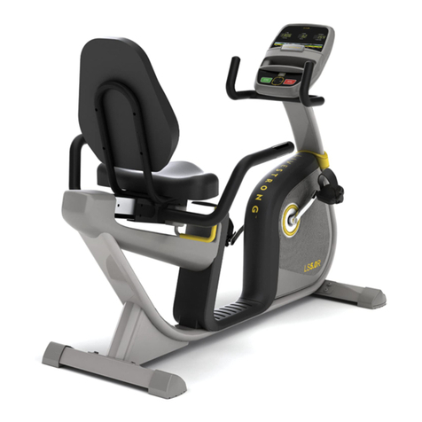
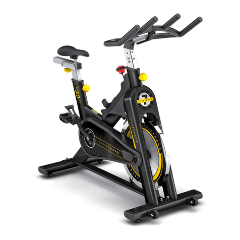
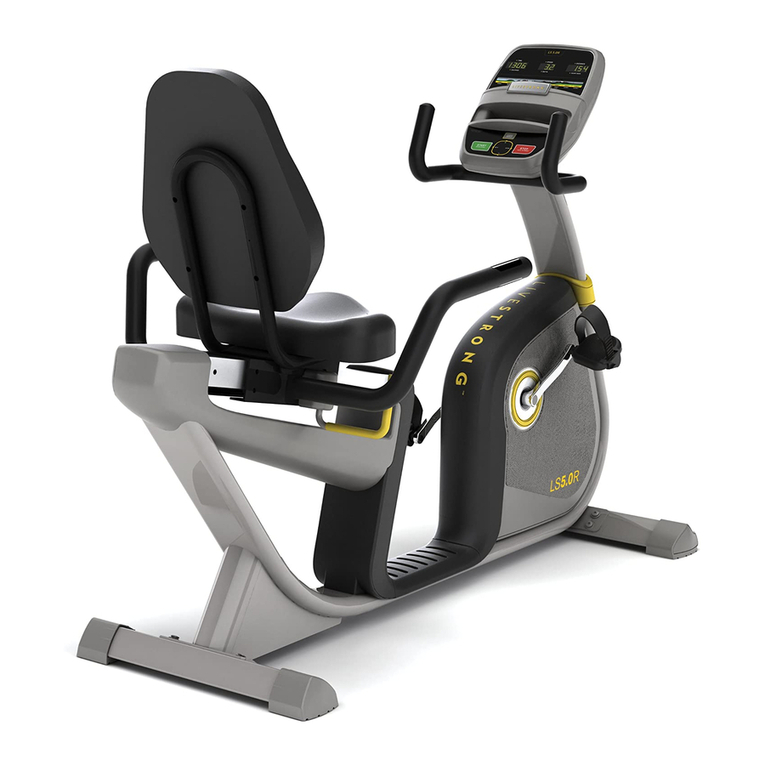
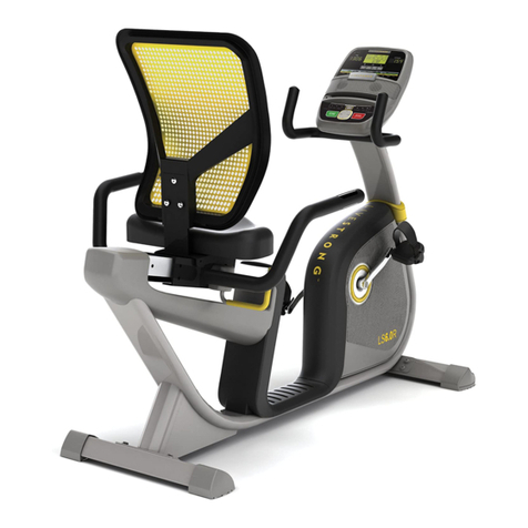
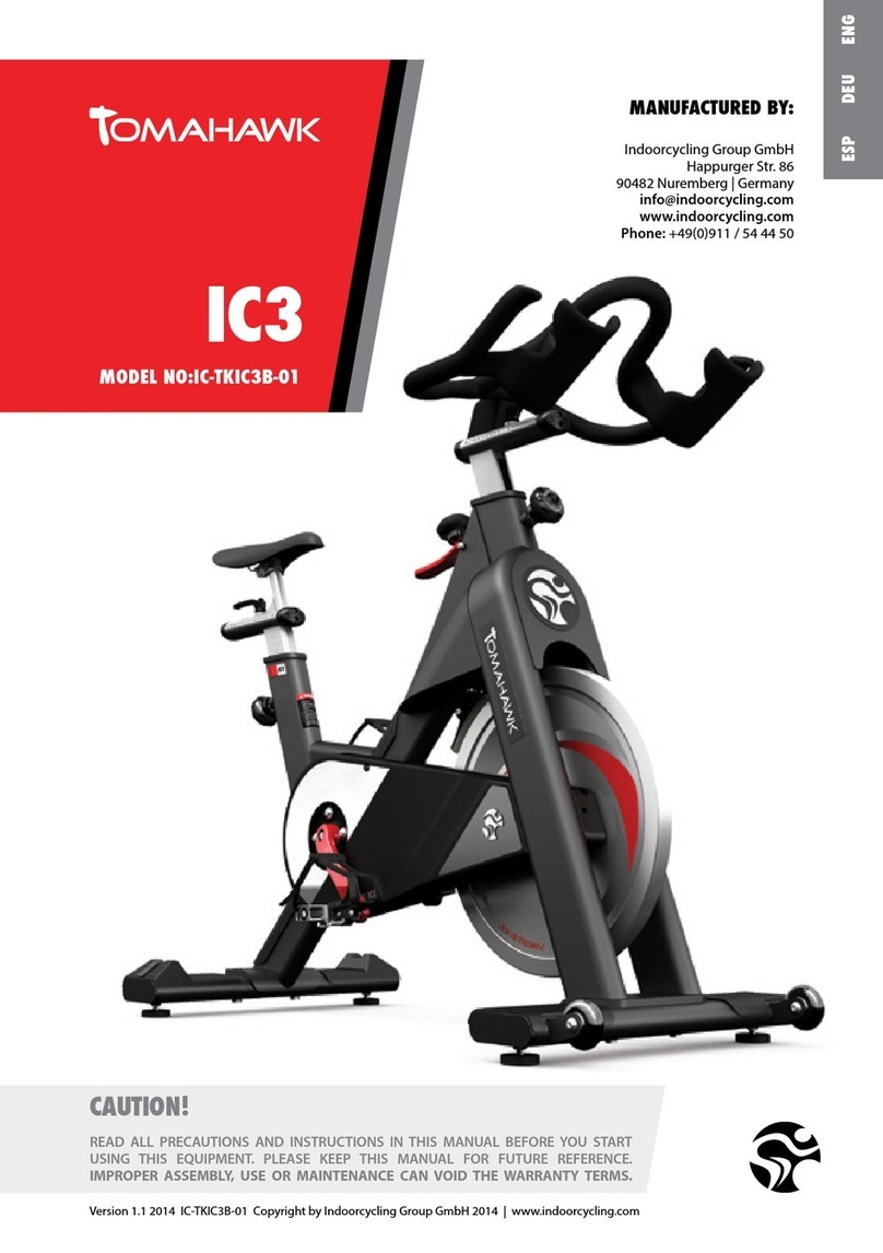
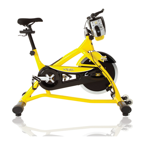
Livestrong 2010 EB LS User manual

Version 1.2 2010 EBLS Copyright by Indoorcycling Group GmbH 2010 | www.indoorcycling.com ENG 1
CAUTION !
Read all precautions and instructions in this manual before using this equipment. Keep this manual
for future reference.
Improper assembly, maintenance or use can void the warranty terms.
LIVESTRONG E-series
model no. 2010 EB LS
Manufactured by:
Indoorcycling Group GmbH
Happurger Str. 84-88
90482 Nuremberg | Germany
www.indoorcycling.com
MATRIX Fitness Systems Corp.
1610 Landmark Drive
Cottage Grove, WI 53527
Toll-free: 866.693.4863
Local: 608.839.8686
ENG ESP

Version 1.2 2010 EBLS Copyright by Indoorcycling Group GmbH 2010 | www.indoorcycling.com ENG 2
TABLE OF CONTENTS
Important precautions page 3
Before you begin page 4
How to assemble the LIVESTRONG E-Series page 5-7
Wireless Onboard Computer & part list (optional accessory) page 8-9
Channel Setting & battery installation (optional accessory) page 10-11
Transmitter & computer assembly (optional accessory) page 12-13
Signal distribution of heart rate & cadence (optional accessory) page 14
Before you start & how to operate (optional accessory) page 16-18
Initial install checks page 19
How to adjust the LIVESTRONG E-Series page 20
Pedal strap adjustment page 20
Saddle height adjustment page 20
Saddle horizontal adjustment page 21
Handlebar adjustment page 22
Resistance adjustment page 23
How to move the LIVESTRONG E-Series page 23
Preventative maintenance page 24
Daily maintenance page 24
Weekly maintenance page 24
Bi-Weekly maintenance page 25
Monthly maintenance page 26-27
Belt drive system page 28
Maintenance activity plan & check lists page 29-30
Explosion drawings of structural components page 31-36
Spare part reference list page 37
Limited warranty page 38
The LIVESTRONG E-Series Bike is according to EN 957 a Class S product for professional
and / or commercial use. Such training equipment is intended for the use in training areas
specially regulated by the person who has the legal responsibility.
Foot print: 55 x 115 cm / 21.7 x 45.3 inch
Weight of bike: 47 kg / 103 lbs
Max saddle height: 115 cm / 45.3 inch
Max handlebar height: 115 cm / 45.3 inch
Max user weight: 130 kg / 287 lbs
The Bike is designed to accommodate most users from 150 to 205 cm / 59.1 to 81.7 inch
body height.

Version 1.2 2010 EBLS Copyright by Indoorcycling Group GmbH 2010 | www.indoorcycling.com ENG 3
IMPORTANT PRECAUTIONS
WARNING!
To reduce the risk of serious injury, read the following important precautions and information before
operating the LIVESTRONG E-Series Indoor Cycle.
It is the responsibility of the owner to ensure that all users of the LIEVSTRONG E-Series Indoor
Cycle are informed of all warnings and precautions.
Operate and maintain the LIVESTRONG E-Series Indoor Cycle only as described in this manual.
Do not operate the LIVESTRONG E-Series Indoor Cycle until it is properly assembled (see page
5-8).
Keep the bike indoors, away from moisture and dust. Do not place the LIVESTRONG E-Series
Indoor Cycle in a garage or covered patio or near water.
from damage, place a mat beneath the LIVESTRONG E-Series Indoor Cycle. Make sure that
there is adequate room around the LIVESTRONG E-Series Indoor Cycle to mount, dismount,
and operate it.
Regularly inspect and properly tighten all parts of the LIVESTRONG E-Series Indoor Cycle as
recommended in this manual. Please replace defective parts immediately and do not use the
bike until repair is performed. Only use original parts from the manufacturer.
Children under the age of 14 should only be allowed use of the LIVESTRONG E-Series Indoor
Cycle with parental consent and guided by a specially trained instructor.
The LIVESTRONG E-Series Indoor Cycle should not be used by persons weighing more than
290 pounds (130 kg).
Always wear appropriate athletic clothes and shoes while operating the LIVESTRONG E-Series
Indoor Cycle. Do not wear loose clothes that could become caught on the LIVESTRONG E-
Series Indoor Cycle or shoes with loose laces.
Before using the LIVESTRONG E-Series Indoor Cycle, make sure that you are familiar with the
operation of the Indoor Cycle (see pages 8-11).
(see page 11).
Keep your back straight while using the LIVESTRONG E-Series Indoor Cycle; do not arch your
back.
If you feel pain or dizziness while exercising, stop immediately, rest and cool down.
If replacement parts are needed, use only manufacturer supplied parts.
1.
2.
3.
4.
5.
6.
7.
8.
9.
10.
11.
12.
13.
14.
15.
WARNING
Before beginning any exercise program, consult your physician. This is especially important for
persons over the age of 35 or persons with pre-existing health problems. Read all instructions before
using. Be aware that incorrect or extensive training may result in serious health injuries. The
manufacturer assumes no responsibility for personal injury or property damage sustained by or
through the use of this product.
ENG ESP
BEFORE YOU BEGIN
Version 1.2 2010 EBLS Copyright by Indoorcycling Group GmbH 2010 | www.indoorcycling.com ENG 4
lower range of the frame. Please register to these in servicing and maintenance lists.
Emergency Brake & Resistance Knob
Saddle
T- Lock
Handle
Adjustment
Knob
Pedal /
Toe Clip
Chain Guard
Maintenance
Cover
Handlebar
Adjustment
Knob
Brake Pad
Flywheel
Transport
Wheel
Levelling
Feet
Dear customer,
Congratulations for selecting the LIVESTRONG E-Series. The LIVESTRONG indoor
tone muscles, and develop endurance. Whether users are beginners or experienced
athletes,theLIVESTRONG E-Seriesoffersworkoutsthatwillhelpuserstoreachtheirindividual
If you have questions after reading this manual, please contact your local distributor or
refer to the website www.indoorcycling.com. Before reading further, please familiarize
yourself with the parts that are labeled in the drawing below.

Version 1.2 2010 EBLS Copyright by Indoorcycling Group GmbH 2010 | www.indoorcycling.com ENG 5
1
3 4
2
Assure that plastic gasket is placed between
stabilizer and frame.
Assure that plastic gasket is placed between
stabilizer and frame.
Assure that black rubber washer is placed
between upper frame and bolt/washer.
Assure that black rubber washer is placed
between upper frame and bolt/washer.
HOW TO ASSEMBLE LIVESTRONG E-Series
SW 17mm
SW 14mm 3mm hand tight
2x
15mm Pedal
Wrench
1x
ENG ESP

Version 1.2 2010 EBLS Copyright by Indoorcycling Group GmbH 2010 | www.indoorcycling.com ENG 6
5 6
7
STOP mark
HOW TO ASSEMBLE LIVESTRONG E-Series
SW 17mm
SW 14mm 3mm hand tight
2x
15mm Pedal
Wrench
1x
a LEVEL HORIZONTAL position and

Version 1.2 2010 EBLS Copyright by Indoorcycling Group GmbH 2010 | www.indoorcycling.com ENG 7
8 9
10 11
STOP mark
STOP mark
STOP mark
HOW TO ASSEMBLE LIVESTRONG E-Series
SW 17mm
SW 14mm 3mm hand tight
2x
15mm Pedal
Wrench
1x
Pedal marked R installed on right crank (clockwise). Pedal marked L installed on left crank
with use of the LIVESTRONG E-Series.
ENG ESP

Wireless Commercial Computer - PRO 1.0
Article no. ST02 01 20
Article no. 02 01 20
Version 1.2 2010 EBLS Copyright by Indoorcycling Group GmbH 2010 |www.indoorcycling.com ENG 8
Optional accessory
wireless commercial computer page 8 - 18

PARTLIST
Version 1.2 2010 EBLS Copyright by Indoorcycling Group GmbH 2010 |www.indoorcycling.com ENG 9
1 2 3
ABC
1x 2x
2x
PZ 2
4
optional
accessory
Computer console Wireless cadence
transmitter Computer
mounting bracket Textile heart
rate chest belt
M5 x 50
M4 x 10 M5
AA
AA
AAA
AAA
AAA
Magnet
5
ENG ESP

Version 1.2 2010 EBLS Copyright by Indoorcycling Group GmbH 2010 |www.indoorcycling.com ENG 10
1
1
2
default setting
The channel transmitting the cadence signal
from the transmitter to the computer console is
pre set. A sticker on the housing indicates the
preset channel on computer & transmitter.
The channel can manually be changed. To
avoid cross reading please assure a clearance
of 52`` (1,3m) between components set on
identical channels or simply swap to another
channel.
To assure that the digital cadence signal is
synchronized, please assure that the channel
setting on the computer console corresponds
with the setting of the cadence transmitter on
the front fork.
Please view picture no. 2 and 3.
2
1
The use of rechargable batteries may lead to male function of the computer and transmitter
units due to a voltage lesser than 1,5V
CHANNEL SETTING & BATTERIE INSTALLATION
hand tight
PZ 2

Version 1.2 2010 EBLS Copyright by Indoorcycling Group GmbH 2010 |www.indoorcycling.com ENG 11
3
4
2
2
The use of rechargable batteries may lead to male function of the computer and trans-
mitter units due to a voltage lesser than 1,5V
CHANNEL SETTING & BATTERIE INSTALLATION
hand tight
PZ 2
ENG ESP

Version 1.2 2010 EBLS Copyright by Indoorcycling Group GmbH 2010 |www.indoorcycling.com ENG 12
5
6
5
sensor
2
Magnet
Magnet
Screws are made of plastic in order to avoid rust point. Do not overtighten and strip the head.
sensor
TRANSMITTER & COMPUTER ASSEMBLY
hand tight
PZ 2

Version 1.2 2010 EBLS Copyright by Indoorcycling Group GmbH 2010 |www.indoorcycling.com ENG 13
7
8
3
1 x B
2 x A
1 x C
3
Please assure that protective rubber strip is used under computer bracket clamp.
TRANSMITTER & COMPUTER ASSEMBLY
hand tight
PZ 2
ENG ESP

Version 1.2 2010 EBLS Copyright by Indoorcycling Group GmbH 2010 |www.indoorcycling.com ENG 14
9
10
120º
digital cadence signal distribution
45º
130 cm
52 inch
analog heart rate signal distribution
UD
bike 1
bike 2
bike 3
cross reading no cross reading
120 cm
48 inch
SIGNAL DISTRIBUTION

Version 1.2 2010 EBLS Copyright by Indoorcycling Group GmbH 2010 |www.indoorcycling.com ENG 15
Wireless data transmission only via chest belt (16 channel
digital cadence and analog heart rate 5,4khz ± 10%)
(integrated chest belt receiver)
based on average values and should only be used for
reference purposes)
TECHNICAL SPECIFICATIONS & FEATURES
ENG ESP

Version 1.1 2010EB Copyright by Indoorcycling Group GmbH 2010 |www.indoorcycling.com ENG 16
the cadence transmitter setting to allow proper cadence reading
tons ( Sun or Flow)
ted from your personal HR chest belt properly
order to transmit signal.
indicates the reception of a compatible analoge HR signal
displayed
how-to instructions)
again for 1 sec.
user data such as time, distance and Kcal, average HR and RPM
display illuminates and automatically turns off after 5 sec.
Time, Distance, Kcal
BEFORE YOU START & HOW TO OPERATE

Version 1.2 2010 EBLS Copyright by Indoorcycling Group GmbH 2010 |www.indoorcycling.com ENG 17
Sun button Flow button
heart rate - actual
heart rate - average
cadence/RPM - average cadence/RPM - actual
training information
training time
mile/km (presetting)
scan functionality for
time, distance and
calories
distance
calorie consumption
WARNING!
Heart rate monitoring systems may be inaccurate. Over exercising may result in serious
injury or death. If you feel faint stop exercising immediately.
BEFORE YOU START & HOW TO OPERATE
ENG ESP

Version 1.1 2010EB Copyright by Indoorcycling Group GmbH 2010 |www.indoorcycling.com ENG 18
If you don´t use the equipment for a prolonged period of time, please remove the
batteries to avoid any damage by leaking or corroding batteries. If batteries have
discharged, remove all residue immediately and insert new batteries into the
computer. If you come into contact with residue, avoid contact with eyes and wash
hands thoroughly.
If possible please use rechargeable batteries to help save the environment. Before
scrapping, please take the batteries out of the computer. When using rechargable
Batteries, please make sure they deliver 1,5 V output.
Signed products or batteries with this symbol may not be
disposed of in the normal domestic refuse. Please
become informed about relevant local laws or guidelines
for the disposal of electrical devices and batteries. And act
accordingly.
BEFORE YOU START & HOW TO OPERATE

The cycle tune-up must be performed at initial installation of the LIVESTRONG E-Series for optimal per-
formance and longevity. Please read and follow all instructions below. If the LIVESTRONG E-Series is not
installed and tuned as described, components may wear excessively and the LIVESTRONG E-Series may
become damaged. If you have questions about the installation, please contact MATRIX Fitness Systems.
lubricant, and White Lithium grease.
1. Make sure that the LIVESTRONG E-Series is level. If the LIVESTRONG E-Series rocks on the
eliminated.
2. Verify Emergency brake function to assure that emergency brake functions correctly.
3. Brake pad calibration: Turn resistance knob counterclockwise as far as possible (minimum bra-
can go.
4. Apply WD40 or Brunox spray lubricant to the brake pad using the lubrication holes on the plastic
part or the brake pad and externally on the felt pad. Make sure brake pad is thoroughly soaked
gallon (3.7 L) at the local hardware store.
5. Apply Lithium grease to the threads on the lower end of the brake rod. First, turn the Resistance
knob clockwise until it stops. Apply a small amount of white lithium grease to the threads on the
brake rod above the two lock nuts. Then, turn the resistance knob counter-clockwise until it stops.
6. Apply Lithium grease on the metal threads of all the adjustment knobs.
7. Verify four (4) Allen nuts on RS pulley for tightness. If loose, apply LocTite Threadlocker Blue-242
and retighten.
8. Verify R and L crank arm Allen bolts for tightness. If loose, apply LocTite Threadlocker Blue-242
and retighten.
resistance load. In case that the belt slips, proceed using the adjustment technique as described
on page (28). Please note that a belt drive gear never shows slack. In case of adjustment do
not apply too much tension.
10. Wipe down bike frame with rag moistened with WD-40
11. Some parts of the LIVESTRONG E-Series may become loose during shipment. Check crank
arms, check all exposed screws, bolts, and nuts, and make sure that they are properly tightened.
12. Verify that computer is reset for Miles vs. Kilometers and RPM measurement is working properly.
Please see computer manual on page 8-18 for instructions on installation of computer.
Customer Service
1. Provide basic maintenance instructions to client and direct them to detailed maintenance instruc-
tions (page 24 )
Version 1.2 2010 EBLS Copyright by Indoorcycling Group GmbH 2010 |www.indoorcycling.com ENG 19
INITIAL INSTALL CHECKS
ENG ESP

HOW TO ADJUST THE LIVESTRONG E-Series
Version 1.2 2010 EBLS Copyright by Indoorcycling Group GmbH 2010 | www.indoorcycling.com ENG 20
The LIVESTRONG E-Series can be adjusted for maximum comfort and exercise effec-
tiveness. The instructions below describe one approach to adjusting the LIVESTRONG E-
Series to ensure optimal user comfort and ideal body positioning; you may choose to adjust
the LIVESTRONG E-Serie cycle differently.
Sit on the saddle and position your feet on the pedals, with the balls of your feet
directly above the spindles of the pedals (see the drawing below). Adjust the pedal
straps so the toe clips (cages) are snug but not too tight. Note: In the case of a Bike
cleats on the opposite surface. If desired, use the shoe cleats with cycling shoes
instead of the toe clips.
Sit on the saddle and slowly pedal until the right pedal is in the lowest position. Your knees
should be slightly bent without a dropping of the hips.
Please do not adjust
handlebar height beyond
the STOP mark on the stem
and ensure the pop pin is
fully engaged and securely
tightened (see page 6).
Please do not adjust saddle
height beyond the STOP
mark on the stem
and ensure the pop pin is
fully engaged and securely
tightened (see page 6).
-
Other manuals for 2010 EB LS
1
Table of contents
Languages:
Other Livestrong Exercise Bike manuals

Livestrong
Livestrong 2010 SB LS User manual

Livestrong
Livestrong LS5.0R User manual

Livestrong
Livestrong LS9.9IC User manual

Livestrong
Livestrong 2010 SB LS User manual

Livestrong
Livestrong LS5.0R User manual

Livestrong
Livestrong LS6.0R User manual

Livestrong
Livestrong LS5.9IC User manual

Livestrong
Livestrong LS9.9IC User manual

Livestrong
Livestrong LS7.0B User manual

Livestrong
Livestrong LS5.0R User manual