Livid Ohm64 User manual

Ohm64
From Livid Wiki
Contents
1 Introduction
1.1 What’s in the box
1.2 Features
2 Controls and Connections
3 Connecting
3.1 For Direct USB Connectivit
3.2 For MIDI Connectivit
3.3 Troubleshooting
4 Editor
5 Support
6 Appendix
6.1 Ohm64 S sex
6.2 LED Control Column/Row Codes
6.3 Assigning Buttons MIDI Values with S Sex
6.4 Controls Naming Convention
6.5 Default MIDI Settings
7 Warrant
7.1 Ohm64 WARRANTY AND RETURN POLICY
Introduction
This instrument is built with all the familiar controls of a standard MIDI controller, instrument, or mixer. The
Ohm64 features assignable LED backlighting, custom designed rubber buttons, and high qualit sliders and
knobs. The control la out was inspired b some of the most innovative and popular audio software programs
that have revolutionized the wa music is created and performed. Ohm64 users will find it to be highl
intuitive and adaptable to a variet of music and video software and makes an ideal companion for hardware
such as analog s nthesizers, video mixers, DJ software, lighting equipment, and other musical instruments.
What’s in the box
Livid Ohm64 Controller
USB Cable
Registration Card
Features
64 button clip bank
8 Faders
1 Crossfader

16 Rotar knobs
6 Function knobs
1 BPM/Tap button
8 Solo / Mute buttons
2 Transform buttons
Controls and Connections
While an of the controls on the Ohm64 can be used for a wide range of functionalit , here are some basic
terms and uses for the controls.
Programmable Clip Bank – The Clip Bank sends out data for activating files, triggering loops,
sequences, or files. The programmable buttons on the Clip Bank can be assigned to MIDI notes or
Continuous Controllers (CCs).
1.
Programmable Sliders – These programmable vertical sliders can be used to adjust effects, mapped to
pitch and volume, or used to manipulate data. The sliders can be programmed to send CC or Pitch
Bend messages.
2.
Programmable Triggers – These programmable buttons can be used to activate effects or mute
channels. The buttons can be assigned to MIDI notes or CCs.
3.
Programmable Knobs – These programmable knobs can be used to adjust effects, EQ settings, and
control pla back. The knobs can be programmed to send CC or Pitch Bend messages.
4.
Programmable Function Buttons – These programmable buttons can be used to activate various
functions within the software such as: switching between channels or banks, selecting tracks, or used
to cue, pla , pause, and rewind our media. The buttons can be assigned to MIDI notes, program
changes, or CCs.
5.
Programmable Transform Buttons – These programmable buttons can be used to transform, mix,
switch, or fade between channels. The buttons can be assigned to MIDI notes, program changes, or
CCs.
6.
Programmable Crossfader – Use the crossfader to control the crossfade, mix, or transition between
channels. The crossfader can be programmed to send increasing values to the left or to the right.
7.
Programmable Tap Button – This programmable button is designed for tapping the BPM. This button
can be assigned to MIDI notes, program changes, or CC’s.
8.

MIDI IN – The MIDI Input port provides a standard 5 PIN MIDI jack for connecting other MIDI
devices to the Ohm64. MIDI input data is then routed over USB to the host computer, and is available
to our software on the second port named “Ohm64 External” (on Windows XP, “USB Audio
Device[2]”)
1.
MIDI OUT - The MIDI Output port provides a standard 5 PIN MIDI jack for outputting MIDI from
our computer, over the USB cable, and to the MIDI jack. The Ohm64 will also send its data out the
MIDI jack. This MIDI Output can be accessed on our computer via the port named “Ohm64
External” (on Windows XP, “USB Audio Device[2]”)
2.
USB – USB Port for powering the Ohm64 and sending MIDI message to and from the instrument.3.
Connecting
To make the Ohm64 controller compatible with industr standard sound and video equipment, the controller
comes equipped with both a USB and MIDI out connection. The USB is designed to connect directl to a
computer and the MIDI out can be used to connect to a MIDI interface, PC soundcard, external soundcard,
or an of the hundreds of MIDI processors and s nthesizers using a standard MIDI cable. The Ohm64 is
completel USB powered and does not require an external power suppl .
For Direct U B Connectivity
The Ohm64 is class-complaint and does not require drivers when using the USB connectivit .
Connect the USB cable from the computer to the USB port on the Ohm64.1.
When the logo on the Ohm64 is illuminated, the device is powered.2.
For MIDI Connectivity
Using a standard MIDI cable, connect the Ohm64 MIDI in and out to the MIDI in and out of our
sound-card or other MIDI interface. The Ohm64 must be plugged into a USB host and have MIDI software
running (even if it's something basic like MIDI Monitor (http://www.snoize.com) or MIDI OX
(http://www.midiox.com) running. This is a b -product of USB-powered class-compliant devices with no
external power source. However, once ou have the Ohm64 connected to a computer and some simple
MIDI application running, ou can send the Ohm's MIDI out the MIDI output jack.
Looking at the back of the Ohm64, the MIDI OUT is the input jack on the right located next to the USB
port, and the MIDI IN is the jack on the left.
Troubleshooting
Make sure our USB cable is properl connected. If ou are using a USB hub, tr connecting the Ohm64
USB cable directl to our computer. The lights should come on once the Ohm64 is connected.
If ou are using a Macintosh Computer running OSX, make sure ou have Ohm64 selected as our device in
the Audio MIDI setup. To access Audio MIDI go to Applications>Utilities>Audio MIDI Setup.
Check to make sure our software is configured to use the Ohm64. Open our application’s preferences to

verif that the software is configured to receive the MIDI messages from the Ohm64 controller.
Windows XP will show the port names as “USB Audio Device” and “USB Audio Device[2]”, though the
“New Hardware Found” popup will show the device as “Ohm64”.
Windows 7 will show our controller as Ohm64 and will automaticall recognize the device.
If ou are still having problems, confirm that ou are receiving MIDI data using MidiMonitor (for OS X) at
http://www.snoize.com/MIDIMonitor/ or MIDIOX (for Windows) http://www.midiox.com.
Editor
For details on editing the MIDI assignments on the Ohm64, click here: Ohm64 Editor
upport
For questions or support please visit our forums at http://forums.lividinstruments.com Here ou will find
answers to man of our questions and ask new ones. We will do our best to answer most of of our
questions within 24 hours.
Appendix
Ohm64 ysex
SYSTEM EXCLUSIVE COMMAND BYTES
The S stem Exclusive message includes the official MIDI Manufacturer ID for Livid, a Product number, and
the Command number. A "wild card" Product number allows the same commands to be shared across
multiple Livid products. These messages can be almost an number of b tes from 7 to (183) b tes.
Note: In this specification, all numbers are hexadecimal unless parenthesized or oth
erwise noted, in which
case the are decimal.
F0 00 01 61 02 NN ... F7
The Product number is 02 for the Ohm64, and the Command numbers, NN, are described below.
COMMAND SUMMARY
00 : individual button map (not supported) *
01 : individual control map (not supported) *
02 : Save User Settings
03 : read presets (ignored) *
04 : Set all LED indicators
05 : Recall User Settings
06 : Factor Reset
07 : Request, multiple subt pes:
07.04 : Request all LED indicators

07.06 : Request Control Surface Snapshot
07.08 : Request MIDI Settings (Local Control, etc.)
07.09 : Request Single MIDI Input mapping
07.0A : Request Analog mapping
07.0B : Request Button mapping
07.0C : Request MIDI Basic Channel
07.0D : Request MIDI Output Merge setting
07.0F : Request crossfader Flip setting
08 : MIDI Settings Response
09 : Map Single LED Indicator
0A : Map Analog Inputs
0B : Map Buttons
0C : Set MIDI Basic Channel
0D : Set MIDI Output Merge
0E : Erase entire MIDI Input Map
0F : Set crossfader Flip
7E : NAK Negative Acknowledge
7F : ACK Positive Acknowledge
Commands 0, 1, and 3 are Ohm "classic" S stem Exclusive commands. Even though the MIDI
Manufacturer ID is different, and the command structure is different as well, these skipped command
numbers pa tribute to what came before.
COMMAND DETAILS
02 : Save User Settings
F0 00 01 61 02 02 F7
All User Settings which can be remembered will be stored in Flash and automaticall restored whenever the
Ohm64 is powered up. The Ohm64 responds with ACK when finished processing this command.
04 : Set all LED indicators
F0 00 01 61 02 04 LL HH LL HH LL HH LL HH LL HH LL HH F7
All (75) LED indicators can be set on or off with this command. There are (12) b tes, or 6 pairs of LL HH.
Values must be 7F or less. The first LL HH pair represents column 1, with each subsequent LL HH pair
representing the next column. Within each pair, LL represents the first 7 rows, and HH represents the
remaining 6 rows. There are (14) bits total for rows, but bit (11) is unavailable and reserved for future use. A
1 bit turns the LED off, a 0 bit turns it on.
The LED columns and rows do not convenientl match up with the ph sical la out of the Button columns
and rows. Using codes as C.R to specif column and row, the LED codes are as follows (all codes are
decimal in this table, and all columns and rows are numbered starting at 1 - the first line is the first Button
column from first to last row, etc.):
64 grid:
1.1, 3.2, 5.3, 1.5, 3.6, 5.7, 1.9, 3.10,
2.1, 4.2, 6.3, 2.5, 4.6, 6.7, 2.9, 4.10,
3.1, 5.2, 1.4, 3.5, 5.6, 1.8, 3.9, 5.10,
4.1, 6.2, 2.4, 4.5, 6.6, 2.8, 4.9, 6.10,
5.1, 1.3, 3.4, 5.5, 1.7, 3.8, 5.9, 1.12,
6.1, 2.3, 4.4, 6.5, 2.7, 4.8, 6.9, 2.12,

1.2, 3.3, 5.4, 1.6, 3.7, 5.8, 1.10, 3.12,
2.2, 4.3, 6.4, 2.6, 4.7, 6.8, 2.10, 4.12
Left/Right crossfader:
5.12, 6.12
1-8 Slider 'mute':
1.13, 3.13, 5.13, 1.14, 2.13, 4.13, 6.13, 2.14
BPM:
3.14
The Ohm64 responds with ACK when finished processing this command.
05 : Recall User Settings
F0 00 01 61 02 05 F7
Recall User Settings from storage, just like what happens on power up. The Ohm64 responds with ACK if
the User Settings are valid, or NAK when no setting have been saved or the memor is unreadable.
06 : Factor Reset
F0 00 01 61 02 06 F7
This will erase the User Settings so that the Ohm64 is factor fresh. The Ohm64 responds with ACK when
finished processing this command.
07 : Request
F0 00 01 61 02 07 RR .. F7
This command allows several t pes of information to be requested. Each request t pe, RR, will be detailed
below. Some request messages require additional information b tes to specific which particular item is being
requested.
The Ohm64 responds with the specified data.
07.04 : Request all LED indicators
F0 00 01 61 02 07 04 F7
Request state of all LED indicators. The Ohm64 will respond with Command 04, and the bits are interpreted
identicall .
07.06 : Request Control Surface Snapshot
F0 00 01 61 02 07 06 F7
Request values for all Analog inputs. The Ohm64 will re-scan ever analog input and report the value with
the usual MIDI Channel Message, even if it has not changed.
07.08 : Request MIDI state (Channel Mode, etc)
F0 00 01 61 02 07 08 F7
Request state of settings that are controlled b MIDI messages, such as Local Control, Omni, Mono/Pol
Mode. The Ohm64 will respond with Response Command 08.
07.09 : Request Single MIDI Input mapping

F0 00 01 61 02 07 09 LL HH F7
Request the current mapping of incoming MIDI messages. LL HH is the 8-bit map code defined under
Command 09 below. Both values must not exceed 7F. LL holds the lower 7 bits, HH holds the most
significant bit. Values of HH greater than 1 are reserved. The Ohm64 will respond with Command 09, which
repeats LL and HH followed b the LED code as CR.
07.0A : Request Analog mapping
F0 00 01 61 02 07 0A F7
Request MIDI map for all Analog inputs. The Ohm64 will respond with Command 0A, and the bits are
arranged identicall .
07.0B : Request Button mapping
F0 00 01 61 02 07 0B F7
Request MIDI map for all Buttons. The Ohm64 will respond with Command 0B, and the bits are formatted
identicall .
07.0C : Request MIDI Basic Channel
F0 00 01 61 02 07 0C F7
Request MIDI Basic Channel. The Ohm64 will respond with Command 0C.
07.0D : Request MIDI Output Merge setting
F0 00 01 61 02 07 0D F7
Request MIDI Output Merge setting. The Ohm64 will respond with Command 0D.
07.0F : Request crossfader Flip setting
F0 00 01 61 02 07 0F F7
Request crossfader Flip setting. The Ohm64 will respond with Command 0F.
08 : MIDI Settings Response
F0 00 01 61 02 08 XX F7
Individual MIDI settings, such as the Channel Mode flags, are combined into the data of this message, XX.
Bit 1 is Omni Mode Off/On. Bit 3 is Local Control Off/On. All other bits, including 0 and 2, are Reserved.
The ma reflect other settings, but the ma change in future releases. Note that this is a response
command onl , and it will be ignored if received b the Ohm64. Use the official MIDI messages to change
these settings.
09 : Map Single LED Indicator
F0 00 01 61 02 09 LL HH CR F7
This command updates the MIDI Input map for a single entr . If HH is 00, then LL specifies the Note
number. If HH is 01, then LL specifies the Control number, but onl valid control numbers are accepted
from 00 to 78. Values of HH above 1 are reserved. CR is the LED indicator Column and Row (see

Command 04 for details), or 7F to clear the mapping for the specified entr .
The Ohm64 responds with a Single MIDI Input mapping for the specified message.
0A : Map Analog Inputs
F0 00 01 61 02 0A (25)*[LL HH] F7
This command updates the MIDI map for all (25) Analog inputs. If HH is 00, then LL specifies the 7-bit
Control number, but onl valid control numbers 00 to 78 are accepted. If HH is 01, then LL selects between
14-bit Control numbers and Pitch Bend. In the latter case, LL between 60 and 6F specifies a Pitch Bend
message on Channel (1) through (16), respectivel . Otherwise, LL selects a 14-bit Control number, of which
the onl valid control numbers are 00 to 1F. All other values for LL, 20 through 5F and 70 through 7F are
reserved for future use. Values of HH above 1 are similarl reserved.
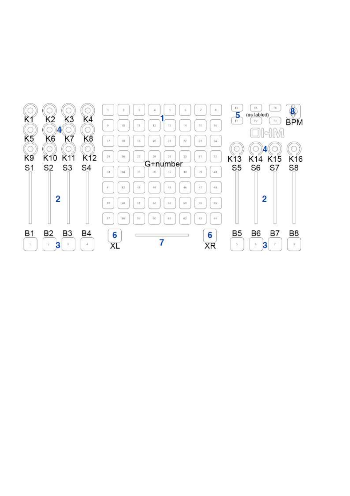
There are (25) sets of LL HH value pairs in this message, each corresponding to the index of an Analog
input. These indices do not convenientl match up with the ph sical la out. The index codes are arranged as
follows (all indices are decimal in this table, and start with 0):
crossfader:
24
eight faders, from left to right:
23, 22, 15, 14, 5, 7, 6, 4
upper left knobs:
17, 16, 9, 8
19, 18, 11, 10
21, 20, 13, 12
right knobs:
3, 1, 0, 2
The Ohm64 responds with ACK when finished processing this command.
0B : Map Buttons
F0 00 01 61 02 0B (88)*[LL HH] F7
This command updates the MIDI map for all (81) Buttons. If HH is 00, then LL specifies the Note number.
If HH is 01, then LL specifies the Control number, but onl valid control numbers are accepted from 00 to
78. Larger values of LL and HH are reserved, with 7A (start), 7B (continue), and 7C (stop) used for MMC.
There are (88) sets of LL HH value pairs in this message, each corresponding to the index of a Button. These
indices do not convenientl match up with the ph sical la out, and there are seven missing codes near the
end which are reserved. The index codes are arranged as follows (all indices are decimal in this table, and
start with 0):
grid buttons are:
0, 8, 16, 24, 32, 40, 48, 56
1, 9, 17, 25, 33, 41, 49, 57
2, 10, 18, 26, 34, 42, 50, 58
3, 11, 19, 27, 35, 43, 51, 59
4, 12, 20, 28, 36, 44, 52, 60
5, 13, 21, 29, 37, 45, 53, 61
6, 14, 22, 30, 38, 46, 54, 62
7, 15, 23, 31, 39, 47, 55, 63
crossfader
64, 72

1-8 Slider 'mute' buttons, from left to right, are:
65, 73, 66, 74, 67, 75, 68, 76
function 1-6:
77, 78, 79, 69, 70, 71
BPM:
87
The Ohm64 responds with ACK when finished processing this command.
0C : Set MIDI Basic Channel
F0 00 01 61 02 0C NN F7
This command sets the MIDI Basic Channel to NN, where 00 through 0F are valid and the rest are reserved.
During operation, incoming Channel messages are ignored if Omni Mode is Off and the Channel does not
match. If Omni Mode in On, then the incoming Channel is not checked, and all messages are interpreted. For
outgoing MIDI messages, the Basic Channel is alwa s used unless an Analog input is mapped to Pitch Bend,
in which case the Channel number is specified b the mapping entr . The Ohm64 responds with ACK when
finished processing this command.
0D : Set MIDI Output Merge
F0 00 01 61 02 0D NN F7
This command allows the Control Surface to merge its messages onto the MIDI output jack, in addition to
USB. NN can be 00 (off) or 01 (on). Other values are reserved.
The Ohm64 responds with ACK when finished processing this command.
0E : Erase entire MIDI Input Map
F0 00 01 61 02 0E F7
This command erases all MIDI Input message mappings. These affect the remote control of LED indicators,
so no remote control will be available immediatel after the map is erased. Because there are as man as
(256) possible MIDI Input messages that can be mapped to an LED, and because multiple assignments to the
same LED can cause conflicts, it is best to start the LED indicator mapping process b first erasing all
entries before filling in the desired mappings, no more than (75), preferabl . The Ohm64 responds with ACK
when finished processing this command.
0F : Set crossfader Flip (left or right as minimum)
F0 00 01 61 02 0F NN F7
This command allows the crossfader response to be flipped. NN can be 00 or 01. Other values are reserved.
The Ohm64 responds with ACK when finished processing this command.
7E : NAK Negative Acknowledge
F0 00 01 61 02 7E F7
This is intended as a wa for the Ohm64 to indicate a problem with the previous message. Unfortunatel ,
when messages are sent too fast, it becomes impossible for the Ohm64 to repl with an thing reliabl , even
NAK. The best approach is to wait for ACK (see below) after sending each message, ra
ther than depend on
NAK to indicate an error. The one exception is Recall User Settings, where the Ohm64
will repl with NAK
if the contents of User memor are empt or otherwise corrupted.

7F : ACK Positive Acknowledge
F0 00 01 61 02 7F F7
ACK means the previous message was handled correctl . Some messages (e.g. Map Single LED Indicator)
simpl repl with a specific command instead of ACK, when more context is needed than a simple
acknowledgment.
MAPPING SUMMARY
Analog to CC; 121 control numbers; 7-bit value
Analog to CC; 32 control numbers; 14-bit value
Analog to Pitch Bend; 16 channels; 14-bit value
Button to Note; 128 note numbers; 1-bit value
Button to CC; 121 control numbers; 1-bit value
Button to MMC; 3 t pes; no value
LED from Note; 128 note numbers; 1-bit value
LED from CC; 121 control numbers; 1-bit value
MIDI IMPLEMENTATION
The following standard MIDI messages are implemented.
S stem Real Time:
MIDI S stem Reset
Channel Mode Messages:
Reset All Controllers
Local Control (connects buttons to corresponding LED indicators)
Pol On / Mono On (both set Omni Off)
Omni On/Off
All Notes Off (turns off all LED indicators)
Controller Numbers:
1B : backlight, 7-bit dimmer
1F : logo, 14-bit (10-bit effective) dimmer
FRONT PANEL CONTROL
The following ke combinations allow front panel control of certain settings.
F4+XL Crossfader Flip off (value increase towards the left, default)
F1+XR Crossfader Flip on (value increases towards the right)
F1+M2 Local Control off (LED indicators under external control onl )
F1+M4 Local Control on (LED indicators controlled b buttons and external)
F1+M6 Omni off (messages received on Basic Channel onl )
F1+M8 Omni on (messages received on all channels)
F2+M6 MIDI out merge off (Control Surface sends on USB onl )

F2+M8 MIDI out merge on (Control Surface sends to USB & MIDI out, default)
XL and XR are the Left and Right crossfader bump buttons, respectivel .
M2 and M4 are the Mute buttons below faders 2 and 4, respectivel .
M6 and M8 are the Mute buttons below faders 6 and 8, respectivel .
LED Control Column/Row Codes
Assigning Buttons MIDI Values with y ex

Controls Naming Convention
Default MIDI ettings

Warranty
Ohm64 WARRANTY AND RETURN POLICY
Damage
Your Instrument should be inspected immediatel upon receiving it. If there are an damages the should be
reported immediatel . All of our instruments are full tested just prior to leaving our plant. Return Polic
All sales of Livid Instruments hardware are given a fifteen (15) da return polic . A controller ma be
returned within fifteen (15) da s of purchase. We will refund the purchase price of the product, less
shipping, immediatel upon receipt of the returned item in as good of shape as it was shipped in. An
damage will be the responsibilit of the customer. We will do our best to determine if damage happened
during shipping and will help the customer b allowing carrier inspection of an damaged items. Software
cannot be returned. An open software packaging is not returnable or available for an refund.
Warranty
Livid Instruments warrants that this product is free of defects in materials and workmanship under normal
conditions for one ear from the purchase date, so long as the product is: owned b the original purchaser;
the original purchaser has proof of purchase from Livid Instruments or an authorized dealer. Warrant does
not include repairs needed due to misuse or abuse.
In the event that Livid Instruments receives written notice of defects in materials or workmanship from such
an original purchaser, Livid Instruments will either replace the product, repair the product, or refund the
purchase price at its option. In the event an repair is required, shipment to and from Livid Instruments and
a nominal handling charge shall be born b the purchaser. In the event that repair is required, a Return
Authorization (RMA) number must be obtained from Livid Instruments. After the RMA number is obtained,
the unit should be shipped back to Livid Instruments in a protective package with a description of the
problem and the Return Authorization (RMA) clearl written on the package.
In the event that Livid Instruments determines that the product requires repair because of user misuse or
regular wear, it will assess a fair repair or replacement fee. The customer will have the option to pa this fee
and have the unit repaired and returned, or not pa this fee and have the unit returned un-repaired.

THE REMEDY FOR BREACH OF THIS LIMITED WARRANTY SHALL NOT INCLUDE ANY OTHER
DAMAGES. LIVID INSTRUMENTS WILL NOT BE LIABLE FOR CONSEQUENTIAL, SPECIAL,
INDIRECT, OR SIMILAR DAMAGES OR CLAIMS INCLUDING LOSS OF PROFIT OR ANY OTHER
COMMERCIAL DAMAGE, EVEN IF ITS AGENTS HAVE BEEN ADVISED OF THE POSSIBILITY OF
SUCH DAMAGES, AND IN NO EVENT WILL LIVID INSTRUMENTS' LIABILITY FOR ANY
DAMAGES TO THE PURCHASER OR ANY OTHER PERSON EXCEED THE PRICE PAID FOR THE
PRODUCT, REGARDLESS OF ANY FORM OF THE CLAIM. LIVID INSTRUMENTS SPECIFICALLY
DISCLAIMS ALL OTHER WARRANTIES, EXPRESSED OR IMPLIED. SPECIFICALLY, LIVID
INSTRUMENTS MAKES NO WARRANTY THAT THE PRODUCT IS FIT FOR ANY PARTICULAR
PURPOSE.
This warrant shall be construed, interpreted, and governed b the laws of the state of New Jerse . If an
provision of this warrant is found void, invalid or unenforceable, it will not affect the validit of the balance
of the warrant , which shall remain valid and enforceable according to its terms. In the event an remed
hereunder is determined to have failed of its essential purpose, all limitations of liabilit and exclusion of
damages set forth herein shall remain in full force and effect.
Livid Instruments, Viditar Inc.
The Ohm64 is handcrafted and assembled in The United States of America.
Retrieved from "http://wiki.lividinstruments.com/wiki/Ohm64"
This page was last modified on 8 October 2010, at 16:46.
Table of contents
Other Livid Recording Equipment manuals