manuals.online logo
Brands
  1. Home
  2. •
  3. Brands
  4. •
  5. Livorsi
  6. •
  7. Boating Equipment
  8. •
  9. Livorsi TTK1150EL User manual

Livorsi TTK1150EL User manual

Trim Tab Installation with Electronic Sensors
Model Number: TTK1150EL, TTK1050EL, TTK950EL, TTK850EL, TTK750EL
1 of 12
LIT-TTEL-ML-INST
Parts Included
(2) Trim Tabs with Sensors
(2) Hydraulic Pumps
(2) Mounting Templates
Harnesses - TTMWH & (2) - TTIWH
Mounting Hardware
Stainless steel hoses sold separately- 2 hoses required per tab
Mounting Tab Location
Available mounting area:
Before selecting a mounting location verify proper clearances inside (transom mounted compo-
nents, etc) and outside (turning drive and propeller clearance) of the boat. Do not mount tabs
in the chine area.
NOTE: The farther the tabs are between each other the better, this will allow you to achieve
the maximum performance out of your tabs.
715 Center Street
Grayslake IL 60030
P: 847-752-2700
F: 847-752-2415
www.livorsi.com
REV A ECO 28610
Billet Trim Tab Installation
Mounting tab location cont.
Transition of the hull to tabs:
Recommended Transtion:
Allows tab to be removed fully from the water flow underneath the boat while under way.
Some applications may require the tab to be mounted even higher to be out of the water flow.
2 of 12
LIT-TTEL-ML-INST REV A ECO 28610
Billet Trim Tab Installation
2x stainless steel oil lines
Port mount
sensor wires Plug
Using the template:
Once the location is determined, use the supplied template for drilling holes.
The template will need to be printed on 11”x17” paper (minimum), template scale is 1:1.
When printing make sure your print settings do not resize the document, keep it at 100%
or disable any scale options.
Example of the Livorsi bolt pattern
Thru hull bolts
Bottom plate area
Depending on your tab model, if equipped with an electric sensor, only drill one hole for the
wire access thru the transom.
NOTE: PORT AND STARBOARD TEMPLATES ARE DIFFERENT
3 of 12
LIT-TTEL-ML-INST REV A ECO 28610
Billet Trim Tab Installation
Mount the tab:
If the Livorsi Trim Tabs are replacing
existing tabs, make sure to seal any
unnecessary holes on the transom. Use a
high quality marine sealer suitable for
underwater use.
Recommended sealant: Marine Grade
RTV / silicone sealant 4200 or 5200.
Use this same sealer and apply liberally
around each fastener, indicator wires and
between transom and upper trim plate. It is
recommended to apply the same sealant to
the inside of the boat.
You may want to apply a piece of tape to
the ends of the hydraulic thru hull fittings to
prevent debris from entering the openings.
If equipped with the electronic sensor
carefully feed the sensor wires thru the
transom.
Secure all mounting hardware.
Installing the pumps and hydraulic lines:
Select the location to mount the hydraulic pumps.
NOTE: Keep pumps as level as possible.
Once mounted, route the hydraulic lines from the tab to the pump. Make sure hydraulic lines
are routed and secured away from any moving components in the boat..
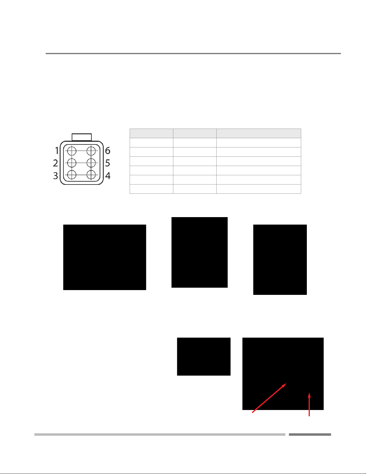
DOWN
Sensor wires
UP
Back view of mounting plate
4 of 12
LIT-TTEL-ML-INST REV A ECO 28610
Billet Trim Tab Installation
12 VOLT
See page 7 for wiring diagram
24 VOLT
See page 6 for wiring diagram
5 of 12
LIT-TTEL-ML-INST REV A ECO 28610
Billet Trim Tab Installation
24 VDC Trim Pump Wiring Diagram
6 of 12
LIT-TTEL-ML-INST REV A ECO 28610
BLACK
(-) GROUND
RED
(+) 24VDC
BLUE/WHITE : UP
GREEN/WHITE: DOWN
BLACK: GROUND
RED/WHITE: POWER
ROCKER
SWITCH
FUSE
(5 AMP)
BREAKER/FUSE
(40 AMP MINIMUM)MOTOR
OIL
RESERVOIR
BATTERY
Recommendation:
Use Good Quality Metal Protectant
or Dielectric Grease on All Wire
Connections.
Billet Trim Tab Installation
12 VDC Trim Pump Wiring Diagram
BREAKER/FUSE
(90 AMP MINIMUM)
7 of 12
LIT-TTEL-ML-INST REV A ECO 28610
BREAKER/FUSE
(90 AMP MINIMUM)
Recommendation:
Use Good Quality Metal Protectant
or Dielectric Grease on All Wire
Connections.
Billet Trim Tab Installation
Sensor Wiring
The sensor wire leads that were fished thru the transom will need to be inserted in to the 6 pin
Deutsch connector and secured with a wedge lock. Below is the pin out.
Pin Number Wire Color Description
1Red PPS1 (5V)
2White PPS2 (5V)
3Blue PPS1 Signal
4Black PPS1 Ground
5Green PPS2 Ground
6 Tan PPS2 Signal
Once pins are pushed thru the connector,
insert the wedge lock to secure pins.
The “arm” of the wedge lock should face the
same side as the connector clasp.
wedge lock
connector sensor wires
from trim tab
8 of 12
LIT-TTEL-ML-INST REV A ECO 28610
Billet Trim Tab Installation
Connections directly to LED Indicator
LED Indicator will have to
be calibrated to trim tabs
9 of 12
LIT-TTEL-ML-INST REV A ECO 28610
Billet Trim Tab Installation
Connections to a Mercury VesselView®
VeseelView® will have to
be calibrated to trim tabs
10 of 12
LIT-TTEL-ML-INST REV A ECO 28610
Billet Trim Tab Installation
Testing:
The hydraulic system will be full of air, the system is designed to self purge this air when the tabs
are raised and lowered.
Purging Air
Before testing the system ensure the pump is filled with oil to the MAX level line.
To purge, fully raise and fully lower the tabs 3X times.
Check the oil level and inspect all hydraulic components for leaks.
Repeat fully raising and fully lowering of the tabs until operation is smooth.
NOTE: While purging the oil will foam (inducing air), allow to sit for 24 hours, fill as needed.
FASTER
SLOWER
MIN
MAX
Types of Oil Reaction Time
ATF
20w20
10w30
11 of 12
LIT-TTEL-ML-INST REV A ECO 28610
Fill the pump with oil:
The pump reservoir has markers indicating the
maximum and minimum oil levels.
The operating temperature and the oil used will
determine the reaction speed of the tabs.
Non-detergent oils recommended.
Billet Trim Tab Installation
Check all hydraulic fittings for leaks
715 Center Street Grayslake IL 60030 P: 847.752.2700 E: [email protected] www.livorsi.com
TTK EL/ML Models: LIT-TTEL/ML-INST-REV0617
12 of 12
LIT-TTEL-ML-INST REV A ECO 28610
Trim Tab Maintenance
Marine growth can interfere with proper operation of the trim tab planes and actuators. To reduce
problems due to marine growth, always return the trim tabs to the full "UP" position after operating
the boat and periodically inspect and clean marine growth from the actuators and planes.
The trim tabs are equipped with 5 zinc anodes to prevent galvanic corrosion. Galvanic corrosion is
the corrosion process occurring when different metals are submerged in an electrolyte. Sea water
is an electrolyte and submerged metal components must be properly protected. The anodes were
installed at the factory and will need to be changed when they are 75% of their original size.
90°
90°
90°
1050 Trim Tab Angles - Pin location 1
For reference only
90°
12°
5°
5° Transom Angle
12° Transom Angle
90° Transom Angle
7.500”
(Clearance from 90°)
5.500”
(Clearance from 90°)
3.250”(Clearance from 90°)
8.500”
5.875”
4”
Pin location 1
Pin location 1
Pin location 1
NOTE: IF EQUIPPED WITH UNDERWATER LED ACCESSORY LIGHTING, ADDITIONAL CLEARANCE NEEDED..
NOT TO SCALE.
22”
22”
22”
715 Center Street Grayslake IL 60030 P: 847.752.2700 E: [email protected] www.livorsi.com
TTK EL/ML Models: LIT-TTEL/ML-INST-REV0617
715 Center Street Grayslake IL 60030 P: 847.752.2700 E: [email protected] www.livorsi.com
TTK EL/ML Models: LIT-TTEL/ML-INST-REV0617
715 Center Street Grayslake IL 60030 P: 847.752.2700 E: [email protected] www.livorsi.com
TTK EL/ML Models: LIT-TTEL/ML-INST-REV0617
REV A
ECO 28610
LIT-TTEL-ML-INST
90°
90°
90°
90°
90°
5°
5° Transom Angle
90° Transom Angle
12°
12° Transom Angle
1050 Trim Tab Angles - Pin location 2
For reference only
5.750”
(Clearance from 90°)
4.875”
7.750”
(Clearance from 90°)
2.500”
9.625”
(Clearance from 90°)
.625”
NOTE: IF EQUIPPED WITH UNDERWATER LED ACCESSORY LIGHTING, ADDITIONAL CLEARANCE NEEDED..
NOT TO SCALE.
Pin location 2
Pin location 2
Pin location 2
22”
22”
22”
REV A
ECO 28610
LIT-TTEL-ML-INST
90°
90°
90°
90°
5°
5° Transom Angle
12°
12° Transom Angle
90° Transom Angle 11”
(Clearance from 90°)
-2.250”
9.250”
(Clearance from 90°)
.500”
6.875”
(Clearance from 90°)
2.750”
1050 Trim Tab Angles - Pin location 3
For reference only
Pin location 3
Pin location 3
Pin location 3
NOTE: IF EQUIPPED WITH UNDERWATER LED ACCESSORY LIGHTING, ADDITIONAL CLEARANCE NEEDED..
NOT TO SCALE.
22”
22”
22”
REV A
ECO 28610
LIT-TTEL-ML-INST
NOTE: IF EQUIPPED WITH UNDERWATER LED ACCESSORY LIGHTING, ADDITIONAL CLEARANCE NEEDED..
NOT TO SCALE.
1050 Trim Tab Dimensions
REV A
ECO 28610
LIT-TTEL-ML-INST

This manual suits for next models

4

Other Livorsi Boating Equipment manuals

Livorsi Single Ignition Key Pad User manual

Livorsi

Livorsi Single Ignition Key Pad User manual

Livorsi TTK750EM User manual

Livorsi

Livorsi TTK750EM User manual

Popular Boating Equipment manuals by other brands

Floe VSD Replacement instructions

Floe

Floe VSD Replacement instructions

SLEIPNER MOTOR AS SE 30 Installation and user manual

SLEIPNER MOTOR AS

SLEIPNER MOTOR AS SE 30 Installation and user manual

Ultraflex UC 95 installation instructions

Ultraflex

Ultraflex UC 95 installation instructions

Hobie Wave Assembly manual

Hobie

Hobie Wave Assembly manual

HydroHoist HarborHoist HH-4400 installation manual

HydroHoist

HydroHoist HarborHoist HH-4400 installation manual

Alamarin Jet AJ 285 installation manual

Alamarin Jet

Alamarin Jet AJ 285 installation manual

Golden GatorVator 4T owner's manual

Golden

Golden GatorVator 4T owner's manual

SKYLOTEC Jackpod Davit Instructions of use

SKYLOTEC

SKYLOTEC Jackpod Davit Instructions of use

Pelican ERGO360 Assembly instructions

Pelican

Pelican ERGO360 Assembly instructions

South Pacific Industrial VS1500 Owner's installation & operations manual

South Pacific Industrial

South Pacific Industrial VS1500 Owner's installation & operations manual

Floe 510-27200-00 Assembly instructions and owner's manual

Floe

Floe 510-27200-00 Assembly instructions and owner's manual

NVequipment SPRAYHOOD Assembly instructions

NVequipment

NVequipment SPRAYHOOD Assembly instructions

CIPTA PERNIKA NUSANTARA SMART VMS Device instructions

CIPTA PERNIKA NUSANTARA

CIPTA PERNIKA NUSANTARA SMART VMS Device instructions

Jackson Flex Drive E owner's manual

Jackson

Jackson Flex Drive E owner's manual

Scheiber BLOC 10 User & Troubleshooting Guide

Scheiber

Scheiber BLOC 10 User & Troubleshooting Guide

Quick AL3 ALEPH Series Installation and user manual

Quick

Quick AL3 ALEPH Series Installation and user manual

Taylor Made 12008 instructions

Taylor Made

Taylor Made 12008 instructions

Floe X-SHALLOW 510-17100-00 Assembly instructions and owner's manual

Floe

Floe X-SHALLOW 510-17100-00 Assembly instructions and owner's manual

manuals.online logo
manuals.online logoBrands
  • About & Mission
  • Contact us
  • Privacy Policy
  • Terms and Conditions

Copyright 2025 Manuals.Online. All Rights Reserved.