LMF Manufacturing B-100 User manual

1
America’s Heat Pellet Stoves
Benchmark Model: B-100
Wood Pellet Stove
U.S.ENVIRONMENTAL PROTECTION AGENCY Certified to comply with 2020 particulate
emission standards using pellet fuel
LMF Manufacturing Ltd.
51 Koppers Ln
Montgomery, Pa 17752.
570-769-7775.
“Made In the USA”
Please read this entire manual before installation and
use of this pellet fuel-burning room heater. Failure to
follow these instructions could result in property
damage, bodily injury, or even death.
Contact local building or fire officials about restrictions
and installation inspection requirements in your area.
Save these instructions
Installer: After installation give
this manual to the homeowner
and explain operation of this
stove.

2
Dear America’s Heat Pellet Stoves Owner:
Congratulations, on the purchase of your America’s Heat Pellet Stove! You have selected the finest
in residential wood pellet heating technology.
Let us here at LMF Manufacturing pass on a few “tips” about installing your stove and heating with
wood pellets.
Whether you install your stove yourself or hire a professional installer, a quality installation is a must
for the safety of your family and for efficient, satisfactory operation of your stove.
Know the quality and characteristics of the pellets that you burn. Pellets can vary greatly from
company to company, from load to load and occasionally from bag to bag. Be extra diligent in your
cleaning program. Remember that 90% of operational dilemmas with a pellet stove are directly
traced to improper installation, poor quality pellets and/or a lack of timely cleaning.
With just a minimum of daily care your America’s Heat Pellet Stoves will provide years of clean,
efficient, comfortable and environmentally sound heating.
Thank you, for selecting an America’s Heat Pellet Stove.
Sincerely,
LMF Manufacturing Ltd
You must consult the authority’s that have jurisdiction (such as
municipal building department, fire department, fire prevention
bureau, etc.) before installation to determine the need to
obtain a permit.
LMF Manufacturing Ltd.
51 Koppers Ln
Montgomery, Pa 17752.
570-769-7775.
“Made In the USA”

3
TABLE OF CONTENT
Welcome
2
Table Of Contents
3-4
Introduction
5
Definitions
5
Cautions
6
Safeties
6
Tamper Warnings
7
Installation Options
7
Installation Notices
7
Building Permit
7
Safety Testing and Listing
7
Installation Cautions and Warnings
8
Installation Checklist
8
EXHAUST SYSTEMS
9-10
Existing Chimney’s
10
Exhaust System Termination
10-11
Exhaust System Sizing
11-12
Outside Air
12
Clearances
13,14,15
Alcove
14
Dimensions
14-15
Stove Installation
15-16
Venting Through The Wall Installation
16
Venting Vertical Through The Ceiling
Mobile Home Installation
16-17
Operating Your Stove
17
How Your Stove Works
17-18
Before Starting Your Stove
18-19
Instructions and Procedures
19
Building and Maintaining The Fire
19
Startup Procedure
19
The Controls
20-22
Error Codes And Possible Meanings
23
Shutting The Stove Off
24
Performance Enhancement Tips
24
Tuning The Stove
25
Extended Operation Periods
25
Stepping Up Your Stove
25
Tightening Up Your Stove
26
PELLETS
27
Pellet Quality
27
PFI Pellet Standards
27
Do NOT Burn
27
Pellet Consumption
27
Factors Effecting Pellet Feed Rates
28

4
Ash and Clinkers
28
STA-CLEAN Grate
28
Fines
29
Combustion
29
REQUIRED CLEANING
30 - 31
Daily Stove Maintenance
32
Bi-Weekly Stove Maintenance
33
Monthly Stove Maintenance
34 - 35
Seasonal Stove Maintenance
33 - 38
REQUIRED MAINTENANCE
39
Disposal of Ashes
39
TROUBLE SHOOTING
40
LIMITED WARRANTY
41
REPLACEMENT PARTS
42

5
Introduction:
Heating with wood pellets has many challenges, but the cost savings and the environmental benefits far
outweigh the challenges. Pellet fuel is “Green House Gas Neutral”, meaning that the carbon products emitted
from burning are absorbed by the trees used for the pellets when growing. Unlike fossil fuels that release
greenhouse gases to the environment, pellet fuels come from renewable resources.
Pellet fuels are produced using national standards established by the Pellet Fuel Institute. The standards
guarantee that the fuel produced at a particular plant overall has the characteristics that were agreed to by the
Institute. These include a maximum pellet length of 1.25”, minimum fines (or sawdust), ash, moisture, salt,
and mineral contents. Does this mean that every bag coming from that plant adheres to the standard? No, it
does not.
Pellets are made from sawdust, and although inspection techniques are very sophisticated, the occasional bad
log gets through. The wood may have high bark content, have mud mixed in or simply be old rotting timber.
These variations in pellet fuels lead to most of the irregularities in burn characteristics, efficiency and stove
failure. Although the America’s Heat Pellet Stove was designed to work with all types of wood pellet fuel
efficiently, there may need to be adjustments made to the stove to make it operate properly.
This manual will help you to optimize the efficiency and reliability of your stove.
Definitions:
Air Intake: Air used for the combustion of the pellets.
Air Damper: Located on the round air intake at the rear on the stove
Automatic Control: Stove operates based on the temperature of the sensor and the users input of desired
temperature or set-point
Burn Pot: Stainless box inside stove in which the pellets burn
Circulation Fan: Right side fan for distributing air through the room
Cleaning: Removal of ash and combustion resins from the stove
Clinkers: Hard Deposits that accumulate in the burn-pot, obstructing air flow
Exhaust: Smoke from combustion of the pellets
Exhaust Fan: Induced draft fan connected to chimney to expel the smoke
Feed-rate: The amount of pellets dropped into the burn-pot per minute or hour. (1 being lowest, 15 being
highest)

6
Inspection: Should be done daily while the stove is cool to check for clinkers and ash accumulation,
integrity of the stove from overheat conditions, and clear exhaust paths.
Heat Capacity: The amount of heat that can be generated from the burning of pellets. Typically, Hardwood
pellets contain 8,000 to 9,000 BTU’s per pound. Simple math assuming a feed-rate of 5 lbs per
hour at 8000 would produce 40,000 BTUs.
Melt-away Tube: Plastic vacuum tube, which if melted from high heat, creates loss of
Vacuum and stops pellet auger from feeding
Modulation: Automatic Variation of the feed rate and exhaust motor speed to meet the heating requirements
of the space (set-point vs. room temperature)
Over-heat Condition: Stove is burning beyond the capacity of the heat exchanger to remove heat. Two safeties
stop the auger from feeding (250 snap and melt-away tube)
Safeties: Built-in safe guards to protect the integrity of the stove and the users of the stove.
Cautions:
The pellet stove is really an advanced version of the original wood stove popularized by Benjamin Franklin.
The advantage of the stove over the fireplace is that more of the heat stays in the building and less goes up the
chimney. As such, the big problem initially was getting the smoke from the stove to the outside world safely.
As piping technology evolved, specialized pipe and procedures were developed for each type of stove to
ensure the safety of the customers. Pellet Vent rated pipe is required for the America’s Heat Pellet Stove.
Make absolutely sure that you have the stove installed according to local codes, ordinances and the owner’s
manual. These pipe installation procedures are designed to remove the smoke of burning pellets safely, but in
addition to this they are designed to allow the piping to survive a chimney fire and protect the house and its
occupants.
The stove itself is designed to the ASTM 1509 standard. Along with “U.S.ENVIRONMENTAL
PROTECTION AGENCY Certified to comply with 2020 particulate emission standards using pellet fuel.”
Among the many provisions of the standard is that the design and construction of the stove is such that it will
contain a fire inside the stove, not allowing it to escape into the space. The shell is made from steel weldments
of sufficient thickness to contain any fire in the stove. Improper maintenance, inspection and cleaning of the
stove can lead to undesired release of smoke into the premises. This is a hazard to health and life. It is
required that smoke detectors and carbon monoxide monitors be installed in the room in which to stove is
installed.
Improper installation and operation of the pellet stove can lead to the accumulation of smoke in the house,
loss of health and life.
TAMPER WARNINGS: This wood heater has a manufacturer-set minimum low burn rate that must not be
altered. It is against federal regulations to alter this setting or otherwise operate this wood heater in a manner
inconsistent with the operating instructions in this manual.

7
Safeties:
250 Degree Overheat Snap Switch: The auger that delivers pellets will stop if the stove overheats. If this
condition happens, very often the stove will appear to be shutting down, the exhaust motor continues to run
and the stove burns up all the pellets. As soon as the overheat condition goes away, the stove may feed pellets
again if the FA1 error has not yet occurred. If this happens, the burn-pot may fill up with pellets until the fire
either re-ignites or goes out and causes an FA1 error. If you suspect that your stove has overheated consult a
service person. Running at a feed rate that is too high or having a failed circulation fan may cause this.
FA1 Error: Loss of Fire. The Exhaust motor continues to run for 30 minutes to make sure all embers are out
and the stove cools down. The most common reason for this is running out of pellets. This error can also
occur on warm days when the feed rate is very low, but this is rather uncommon. As stated above, if this error
occurs and burn pot is full of pellets or there is a pellet jam, a service person should be consulted before re-
firing the stove.
140 Degree Snap Switch: After the stove is shut-down, this blower safety will continue to make the
circulation fan run as long as the internal temperature of the stove is more than 120 degrees. If this switch has
failed, the circulation fan will always run.
Vacuum Pod: This safety is wired to the auger motor through the red wires. If there is a loss of vacuum in the
stove, it will open and not allow the feed of pellets. This can occur if the exhaust fan fails, the exhaust fan fuse
blows, or the chimney gets plugged up. An open door or pedestal door can lead to a lack of a vacuum
reading. As with the melt-away tube and the 250 overheat, a loss of vacuum will cause no pellets to drop.
Fuse Block: The permanent fuses on the fuse block are designed as safeties. The fuse for the exhaust blower,
for example, is designed to blow if the chimney is plugged. Because each fuse is labeled on the board, it
makes it easy to diagnose the failure of the stove. The fuses are permanently affixed to the board so that
improper fusing cannot happen.
Melt-away Tube: In the event of an extreme overheat condition; the special tube will be breached, causing a
lack of vacuum and no feed to the auger motor.
110 Degree Snap Switch: This snap switch is located on the exhaust motor and connected with control wiring
to the control board. The purpose of this switch is to sense the presence of fire in the stove. If the stove is hot,
during shut-down, this snap switch is sensed constantly, keeping the exhaust motor running until the fire is
completely out
INSTALLATION OPTIONS
The America’s Heat Pellet Stove model “B-100” may be installed to code in both conventional
and mobile homes.
INSTALLATION OPTIONS INCLUDE:
1. A FREESTANDING STOVE: Set on a pedestal and placed on a non-combustible floor pad.

8
INSTALLATION NOTICES
SAFE INSTALLATION NOTICE
Your America’s Heat Pellet Stove must be properly installed to meet the safety listing of the stove.
Failure to strictly follow these installation instructions could result in the possibility of a house fire,
property damage, bodily harm or even death.
BUILDING PERMIT
Local building codes must be followed and necessary building permits obtained from local
building officials.
SAFETY TESTING AND LISTING
America’s Heat Pellet Stoves have been tested and listed by Intertek Laboratories, an accredited
testing laboratory, in accordance with the requirements in UL1482 and ASTM standards for solid fuel
heaters, hearth stoves, fireplaces and inserts. The safety label is located on the right side of the
pellet hopper cover. This safety label contains installation specifications that must be followed in all
installations of America’s Heat Pellet Stoves.
HEAT OUTPUT RANGE
9,000 - 18,000 Btu/hr
INSTALLATION CAUTIONS & WARNINGS
The installation drawings shown in this manual are only a few examples of many appropriate
installation designs. Many other designs that meet local code, stated installation requirements of
this manual, the stove’s label and “PL” vent manufacturer’s requirements may be acceptable.
NOTE: All stove owners, operators and installers will want to read and become thoroughly
acquainted with the information in this manual before installation and operation of the stove begins.
1. THIS WOOD HEATER NEEDS PERIODIC INSPECTION AND REPAIR FORPROPER
OPERATION. IT IS AGAINST FEDERAL REGULATIONS TO OPERATE THIS WOOD
HEATER IN A MANNER INCONSISTANT WITH OPERATING INSTRUCTIONS IN THIS
MANUAL.
2. “WARNING” America’s Heat Pellet Stoves MAY NOT BE INSTALLED IN A SLEEPING
ROOM
3. All stoves must be placed on non-combustible material.
4. Caution must be taken to avoid cutting any electrical wires or water pipes that might be in the
vicinity of holes used for the exhaust venting and outside air systems.
5. America’s Heat Pellet Stoves operate with a slightly positive venting system. For the safety
of all people, animals and plants in the vicinity of your stove, the exhaust system MUST BE
CORRECTLY INSTALLED AND MUST BE AIR TIGHT!
6. All installations must meet all codes, “PL” vent manufacturer’s requirements an all
requirements in this manual. NOTE: A FAULTY INSTALLATION MAY PRESENT A
SERIOUS SAFETY HAZARD AND MAY RESULT IN LOSS OF PROPERTY, LIFE AND
VOID THE WARRANTY.

9
7. CAUTION: Any alteration of your stove voids the warranty and may cause a safety
hazard.
8. CAUTION: THE STRUCTUAL INTEGRITY OF THE MANUFACTURED HOME FLOOR,
WALL, AND CEILING/ROOF MUST BE MAINTAINED
INSTALLATION CHECK LIST
Complete this checklist prior to lighting the first fire in your stove.
Unless you are knowledgeable and experienced in stove installation, we RECOMMEND your
America’s Heat Pellet Stove receive a Pre-delivery Check and be installed by an Authorized
America’s Heat pellet stoves Dealer or Factory Service Representative.
Stove owner has read and understood this manual. SAVE THIS MANUAL!
Stove owner has obtained all necessary permits for installation.
The Stove received a “Pre-delivery” check by the AMERICA’S HEAT PELLET STOVES Dealer
or factory sales representative.
Installed by an Authorized AMERICA’S HEAT PELLET STOVES Dealer or factory installation
representative.
Stove inspected after installation by an Authorized AMERICA’S HEAT PELLET STOVES Dealer
or factory technician. .
Installation meets all requirements listed in this manual.
Installation passed all local code requirements.
Complete Limited warranty registration card mailed to: LMF Manufacturing Ltd.
EXHAUST SYSTEMS
GENERAL
1. SAFETY LISTED, 3 OR 4 INCH “PL”vent must be used on all FREESTANDING AND
BUILT IN STOVE installations. A 3 to 4 inch safety listed adapter must be used on your
stove when 4-inch vent pipe is used (See item 14 below.)
2. Horizontal exhaust system runs of over 15 feet are not recommended
3. Exhaust systems must not be run in a downward direction (always maintain some vertical
rise).

10
4. Exhaust systems with over 3 tees and/or elbows may not draft properly.
5. All areas of the exhaust system must be installed so both vertical and horizontal runs may be
periodically inspected and cleaned.
6. A clean out tee must be used at the bottom of all vertical runs to collect fly ash and for easy
cleaning. In some installations, 4 way tees may be needed for easy cleaning.
7. The “PL” vent manufacturer’s installations and clearance requirements must be followed.
8. All exhaust system joints must be fastened with at least three screws. System joints
within the building should be sealed with RTV silicone to assure a long term, exhaust
tight seal.
9. Some exhaust pipe surfaces can get hot enough to cause burns if touched by people or
animals. Shields or guards, with proper “PL” vent clearance may be required for some
installations.
10.Hearth stoves must be installed with “PL” vent for that portion of the venting system between
your stove and a damper plate or to a fireplace shroud if one is used.
11.Your stove may not be placed in or vented into a gas fireplace.
EXISTING CHIMNEYS
12.Existing chimneys must be thoroughly cleaned when they are used in a pellet-stove
installation.
13.DONOT INSTALL A FLUE DAMPER IN THE EXHAUST VENTING SYSTEM OF THIS UNIT.
14.DO NOT CONNECT THIS UNIT TO A CHIMNEY FLUE SERVING ANOTHER APPLIANCE.
(Ex. stoves, furnaces, fireplaces etc.)
15.Single wall, 3 or 4 inch, solid or flexible pipe, stainless steel only, may be used for the
portion of the exhaust system that is behind a metal shroud and is inside a fireplace or
chimney when inserts are placed in a masonry or factory built wood or coal burning fireplace.
16.When venting a stove or insert into an unlined masonry chimney, a stainless steel liner must
be used inside the masonry chimney. When a chimney liner is used, extend the liner to the
top of the chimney. Seal the top of the chimney with a steel chimney cap.
EXHAUST SYSTEM TERMINATION (Figures 3 & 4)
17.Provide at least 5 feet of vertical rise when the exhaust system is terminated on the
prevailing wind side of the building. In this type of installation, a power interruption may
potentially cause smoke to escape from the stove into the house if the exhaust system does
not have at least 5 feet of vertical rise.

11
18.Do not terminate the exhaust system in any enclosed or semi-enclosed area such as
carports, garage, attic, crawl space or any space where exhaust gases can concentrate.
19.Exhaust gases must be directed so they are not a hazard to people entering the building or
cause fires.
20.The exhaust system MUST NOT TERMINATE LESS THAN:
1 foot away from the wall it penetrates through
2 feet above the roof line when extending through the roof
5 feet from any building opening through which the exhaust gases may enter, (i.e.
doors, air intakes an windows which can be opened)
7 feet above a public walkway
2 feet from adjacent buildings
3 feet from plants
1 foot above grade
Figures 3 and 4 are a guide to the application of exhaust system termination requirements.
“Install vent at clearances specified by the vent
manufacturer”
EXHAUST SYSTEM SIZING
The exhaust pipe on all America’s Heat Pellet Stoves are 2.875 inch OD. A3 inch exhaust system
pipe will slip over the outside of your stove’s exhaust pipe. For installations requiring a 4-inch “PL”
vent, a 3 or 4 inch ”PL” adapter must be placed on your stove’s exhaust pipe.

12
Elbows, tees, vertical rise, horizontal run and length of pipe all effect how exhaust gases flow
through an exhaust system. Adjusting the size of the exhaust system to compensate for these
variables may help improve exhaust gas flow and overall performance of your stove. Apply the
“VARIABLES”, listed in the table below, to the different pieces of exhaust system materials and to
venting pipe run in a horizontal direction.
Example 1: An exhaust system going straight out the wall with 2 feet horizontal “PL” vent, into a
TEE with a clean out cap, then running vertical for 5 feet, then into a 90 degree elbow and
terminating with a 45 degree elbow, installed at sea level. Total length of the system is
approximately 10 feet.
Example 2: The same system as in example 1 installed at an elevation of 6,000 feet. To estimate
the size of the exhaust system use the following factors:
VARIABLES
Example 1
Example 2
* The total length, in feet, of the exhaust
system
10
10
* Add 3 feet for each foot of horizontal run.
(3 x ?)
6
=
6
* Add 5 feet for each 90 degree elbow or
tee
(5 x ?)
10
=
10
* Add 3 feet for each 45 degree elbow
(3 x ?)
3
=
3
* Add 2.5 feet of each 1,000 feet of altitude
(1.5 x ?)
0
=
0
Total Factored Length
29
38
Required size of exhaust system
3 or 4”
4”
If the total factored length is under 30, use a 3 or 4-inch exhaust system
If the total factored length is 30 or greater, use a 4-inch exhaust system
NOTE: 4 inch “PL” vent may be used in any installation.
NOTE: Always increase the size up to a 4” exhaust system if in question of the size.
The above are guidelines only. The importance of proper sizing of the exhaust system is to assure
adequate exhaust draft. Inadequate exhaust draft results in a poor flame and inefficient burning.
OUTSIDE AIR
1. Outside air is REQUIRED ON ALL MOBILE HOME INSTALLATIONS.
2. Outside air is recommended for all other installations, especially if installed in a well-
insulated house.
3. Steel pipe, (B) only, either solid or flexible must be used in all outside air installations.
NOTE: Non-metallic material MUST NOT BE USED for outside air installations.
4. A wind shield, ©, over the termination of the outside air pipe or a 90 degree elbow or bend
directed away from the prevailing winds MUST be used when an outside air pipe in installed

13
through the side of a building. Keep the outside air pipe termination at least 1 foot away from
the exhaust system termination.
5. When outside air is taken from an existing chimney the exhaust system must not terminate in
the same chimney.
6. The outside air pipe on your stove is 2” OD. The outside air-connecting pipe must be at least
2” ID. The outside air-connecting pipe must be as short and free of elbows as possible, and it
must fit over (A), not inside, the outside air pipe of your stove. You must use a piece of ¼”
rodent screen over the inlet.
CLEARANCES
Minimum
STOVE
clearances
to Mini
mum
distance the
non-
combustible
Combustible
s, Figures
6,7, & 8
FLO
OR PAD
must extend
beyond
Your stove. Figure 9
inch from the back
Inch from the sides
1 inch from the corners
16 inches from the top
18 inches from the front
of your stove to items such
as furniture, plants and
draperies
6 inches from front of pad
0 inches from the back
6 inches from the sides
All stoves must sit on a non-
combustible floor pad/material.

14
ALCOVE
Minimum
clearances to
combustibles
for a stove.
(Figures 10
and 11)
1 inch from the
back
2 inches from
the sides
16 inches from
the top

15
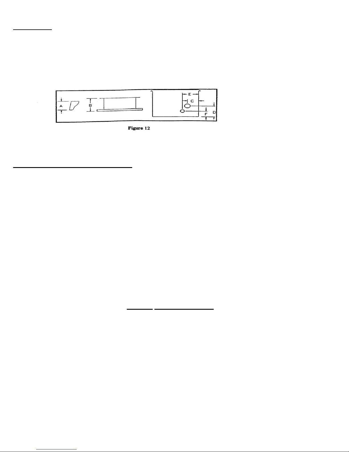
DIMENSION: Leg, pedestal, exhaust outlet and outside air outlet dimensions are (Figure 12)
Legs (A) 6 ¼” 6 ¼” Under Stove
Pedestal (B) 9 ½” 9 ½” 9 ½” From Stove’s Left Side
Center of the (C ) 3 7/8” 3 7/8” 3 7/8” 3 7/8” From Stove’s Left Side
Exhaust pipe (D) 7 5/8” 7 5/8” 7 5/8” 7 5/8” From Stove’s Bottom
Center of the (E) 8 3/8” 8 3/8” 83/4” 8 1/8” From Stove’s Left Side
Outside air (F) 3 7/8” 3 7/8” 3 7/8” 3 7/8” From Stove’s Bottom
STOVE INSTALLATION
Through the wall, direct installation. (Figure 13)
1. Select the location for your stove, design and exhaust system and determine the brand and size
of “PL” vent to be used.
2. Following the “PL” vent manufacturer’s specifications, mark and cut a hole through the wall to
accommodate the wall thimble, (A), and the outside air pipe, (B), if outside air is to be used. Install
the wall thimble, (A).
3. Position the floor pad, (C). Insert the proper size of “PL” vent, (D) through the wall thimble, (A).
Place your stove on the floor pad, (C ) close to its final position. Leave room to connect the “PL”
vent to your stove. Place a bead of RTV silicone around the end of your stove’s exhaust pipe, (E).
Connect the length of “PL” vent, (D) which is in the thimble, (A), onto the stoves exhaust pipe (E).
Place your stove in its final position on the pad. Note: If 4” PL vent is required, use an increaser,
(K), on the stove exhaust pipe.
4. Required: On the outside of the building attach a 45 degree “PL” type elbow, (F) onto the end of
the horizontal “PL” vent, (D). Optionally, place a rodent screen cap, (G), (may be required in some
locals), on the end of the elbow, (E), (HIGHLY RECOMMENDED: RATHER THAN A 45-DEGREE
ELBOW outside of the bldg. AFTER ITEM D FIRST ATTACH a 90-degree elbow to the
horizontal “PL” vent. Place a 5’ length section of “PL” vent (NOT SHOWN IN DIAGRAM)
going up, and then attach a 90-degree elbow to the vertical section. This will give system
some natural draft, which will evacuate smoke in the event of a power failure.
5. If outside air is used, install the outside air pipe, (B). Seal the outside air pipe, (B), to your stove’s
outside air pipe, (I) with RTV silicone. Make sure the outside air pipe fits over, (not inside) your
stove’s outside air pipe, (I). Install either a 90-degree elbow on the end of the outside air pipe, (H) or
install a windshield, (J).

16
VERTICAL INSTALLATIONS (Figures 14, 15, 16, 17, & 18)
Your America’s Heat Pellet Stove may be installed using many different vertical designs. Follow the
same basic steps in locating your stove, attaching the exhaust system and outside air intake to your
stove as described in “STOVE INSTALLATION” and the “PL” vent manufacturer’s procedures for
installing through a wall, ceiling, eve and roof. Common, (but not inclusive), vertical installation
designs are:
1. Vertical, through the ceiling, through another room or space, or attic, then through the roof
terminating with a rain cap. Figure 14
2. Horizontal, out the wall, then vertical to a minimum of 5 feet, into a 90-degree elbow and
terminating with a 45-degree elbow pointed downward. Figure 15
3. Horizontal, out the wall, then vertical through the eves and roof, terminating with a rain
cap. Figure 16
6. Either single wall stainless steel rigid or flexible pipe “PL” vent may be used as the exhaust vent for
the portion of the insert’s exhaust system that extends past the clean out TEE that is attached to
your insert.
MOBILE HOME INSTALLATION
Your America’s Heat Pellet Stoves has been tested and listed for mobile home installation. In
addition to all previously detailed installation requirements, mobile home installations must meet the

17
following requirements and must be in accordance with the Manufactured Home and Safety
Standard (HUD), CRF 3280, Part 24.
1. Permanently bolt your stove to the floor, (A). (Figure 21)
2. Electrically ground your stove or the pedestal to the steel frame of the home. Use a number 8
gauge copper, (B) or equivalent.
3. The stove must have a permanent outside air source with a ¼ inch rodent screen over the
inlet.
4. “CAUTION” The structural integrity of the mobile home floor, wall ceiling and roof must be
maintained.
NOTE: Your America’s Heat Pellet Stoves may be installed in a mobile home as a “Free
Standing Stove”, a “Hearth Stove”
OPERATING YOUR STOVE
Your America’s Heat Pellet Stove is neither a cordwood stove nor a furnace, the operations and
maintenance of your America’s Heat Pellet Stove are unique and should not be considered to be like
a wood coal stove, gas, electric propane or oil heater.
HOW YOUR AMERICA’S HEAT PELLET STOVE WORKS
Fuel in the form of wood pellets is stored in the hopper. An auger delivers the pellets to the burn
pot. When you flip the power switch from the off position to the on position the stove starts the boot
up process. When the power is switched on the display will flash startup codes and display the
current temperature. The fuel rate is set by adjusting the current set temperature.

18
A fan provides combustion air to the burn box. The amount of combustion air in the burn box
automatically changes as the fuel rate changes. The higher the fuel rate, the larger the amount of
combustion air and visa versa. The fuel burns in the burn pot, producing heat. Some heat radiates
out the front of your stove. The majority of the heat passes around the heat exchange tube. Room
air is blown into the exchange tubes, is heated and moved into the room by the room air fan. A
small amount of heat must pass out of your stove, along with exhaust gases, into the atmosphere.
The ever-clean oscillating grate reduces ash build up in the burn grate.
Your stove’s heat output can be adjusted by setting the built in thermostat. The thermostat display
window, displays the current temperature inside the room and may flash any errors that the have
occurred.
When the room temperature is below the set point the stove automatically feeds pellets into the burn
pot. The combustion chamber fan will start, and after the pot has filled the automatic igniter will
begin to glow and light the pellets inside the burn pot. After the burn pot has reached a specific
temperature the room air fan will startup and blow hot air from the air tubes. The stove will continue
to burn until the room temperature has reached the set point.
You will learn what the noises are that your stove makes. When the auger is running you will
hear the pellet fall gently down the feed shoot and into the burn pot. You will also hear a
small hum from the exhaust chamber fan and the room air fan. You will soon be able to
distinguish the normal operating sounds that your America’s Heat Pellet Stove produces.
Your stove can run efficiently over extended periods of time and at different heat output levels as
along as the fuel supply is uninterrupted and timely cleaning and maintenance is performed. An
example of how improper cleaning effects operations of the exhaust pressure switch will shut the
pellet supply off and your stove will shut off if the exhaust system becomes plugged.
The bottom plate in the “Sta-Clean” burn grate moves back and forth constantly forcing incoming
combustion air under the burning pellets. This constant movement of combustion air greatly
decreases the amount of ash build up, reduces clinker formation, gives a cleaner burn and prolongs
the life of the burn grate.
BEFORE STARTING THE STOVE FOR THE FIRST TIME
(Figures 22, 23 & 24)
1. Carefully read this “Owner’s” Manual. Complete the “Installation Check List”
2. Obtain final inspection and approval by local building officials.
3. Carefully clean all marks off the gold plated parts before the first fire is lit. Use a soft
cloth and a “Windex” type cleaner. Caution: Never use an abrasive cleaner on any part
of your stove.
4. Polish the hopper to remove the oil type coating used to prevent rusting.

19
5. Have your Authorized America’s Heat Dealer demonstrate all the operational, cleaning
and maintenance steps necessary for your stove.
6. Sign and mail the limited warranty card.
7. Before STARTING THE STOVE check to make sure the burn grate is clean and the Ash
Pan is not full. Verify that the stove door is securely shut.
Caution: Never use gasoline, gasoline-type lantern fuel, kerosene, charcoal lighter fluid, or
similar liquids to start or ‘freshen up’ a fire in this heater. Keep all such liquids well away
from the heater while it is in use
Instructions and procedures for building and maintaining the fire.
Start Up
1. Fill the hopper with quality pellets.
2. Close the hopper door.
3. Plug in the stove to any single 110 outlet. Flip the toggle switch from the off position to the
on position.
4. Press and hold the Set button and adjust the set temperature with the High and Low
buttons.
5. After the burn pot has a fair amount of pellets in it, the igniter will begin to glow and the
pellets will begin to burn. You can observe this by looking directly at the burn pot.
6. The stove will light in 1 to 5 minutes.
NOTE: If the fire does not start your stove will continue to feed pellets and the fans will run for
approximately 30 minutes. The stove will then automatically shut off. If this happens, some
unburned pellets will build up in the burn grate. You must turn off the toggle switch and unplug
the stove. You should have no more than ¾ of a cup of pellets inside the burn pot. If you do you
must, clean the excess pellets out of the burn pot and follow the above “Using the Stove for the First
Time” steps.
NOTE: Never use colored paper, cardboard, solvents, trash or garbage to light your stove or
maintain a fire.
NOTE: Some odors may be given off a new stove during the initial few hours of burning while
the stove and the paint are being cured. These odors are not harmful. However, ventilating the
room until the odors disappear is strongly recommended. CAUTION: Never use liquid or volatile
fire starters to start a fire in your stove! Do not install or operate your stove in any room where
any liquid or volatile fuels or any other highly combustible items are in the air or stored in the room.
These could cause a safety hazard.

20
Figure 22
THE CONTROLS
Power Toggle Switch, controls electricity to flow to your stove’s electrical components.
When it is switched to the on position it will allow codes to be displayed in the “Temp Display”
window and then it will display the current room temperature. When an error code is
displayed this must be switched to the off position and the stove must be unplugged
for 1- 2 minutes. When the switch is in the off position the stove will not operate. Refer to
the Error codes in (Figure 22a)
Temp Display, this window will display all the information that the computer needs to tell you.
If the stove is operating correctly the current room temperature will be displayed. If there are
other errors please refer to the error guide for help. Refer to the Error codes in (Figure 22a)
High Button, adjusts the stove temperature higher. (When pressed in conjunction with the
Set Button).
Low Button, adjusts the stoves temperature lower. (When pressed in conjunction with the
Set Button).
Set Button, the set button when depressed will display the temperature at what the stove is
currently set to maintain. When the Set button is pressed and held, and the High button is
depressed the set temperature will rise. When the Set button and the Low button are
depressed the set temperature will be lowered.
Fresh Air Intake Control, (Located on the rear of the stove), you can fine-tune the flame and
the speed at which the pellets burn by adjusting this intake. When the intake is open it allows
the maximum amount of air into the firebox, burns the pellets the fastest. When the intake is
closed it limits the amount of air allowed into the firebox and burns pellets slower. This is how
you adjust the quality of the fire.
Table of contents
Popular Stove manuals by other brands

Spectrum
Spectrum winco NGSP-1 Operating instructions manual

Dimplex
Dimplex DCS19W owner's manual

Cumberland Stove Works
Cumberland Stove Works MF3800 Operation and maintenance manual

Vogelzang International
Vogelzang International Sentry Coal VG810CL owner's manual

Jetmaster
Jetmaster Mark 2 Gas Coal installation instructions

Arada
Arada Stratford user guide

Procom
Procom SSU320RHN-GB owner's manual

Haas+Sohn
Haas+Sohn Varde 275.15 ST Assembly instructions

Alfa Plam
Alfa Plam DONNA 70 Instructions for installation and handling

Comfort Bilt
Comfort Bilt HP22N owner's manual

Sunsystem
Sunsystem BURNiT PM Comfort Plus Series Service manual

diLUSSO
diLUSSO R4 Installation and operating instructions