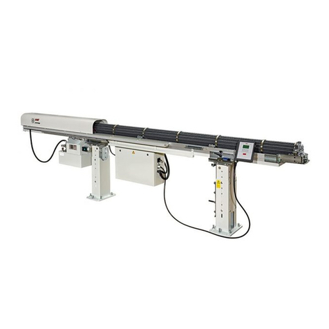
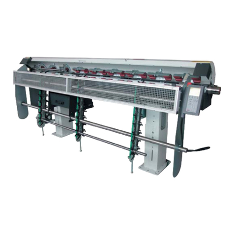
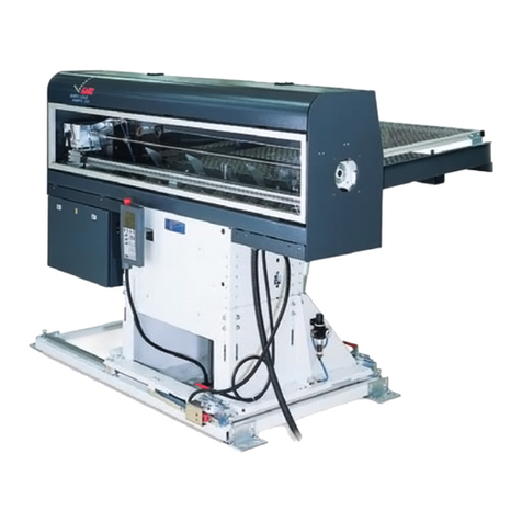
LNS ECO LOAD Series User manual

Instruction manual
ENG
9.ECO.01.ANG


I
ECO LOAD
E4
04.04.08
TABLE OF CONTENTS
1. Introduction 1
1.1. Safety instructions 1
1.2. Floor plans 2
1.3 Technical data 3
2. Installation 4
2.1. Lifting plan 4
2.2 Distance between the feeder and the lathe 4
2.3. Vertical alignment 5
2.4. Horizontal alignment 6
2.5. Securing to the floor 6
3. Mechanical Installation 7
3.1 Assembling the loading system 7
3.2 Assembling the bar magazine 7
4. Commissioning 8
4.1. Connections 8
4.2. Pneumatic diagram 9
4.3 Safety 10
5. Electrical Components 11
5.1 Electrical equipment 11
5.2 Electrical control cabinet 12
5.3 Diagrams 13
5.4 Layout 24
5.5 Inputs / Outputs 25
5.6 Standard interface CE 27
5.7 Standard interface USA 29

II
ECO LOAD
6. Start-up Procedure 31
6.1 General comments 31
6.2 Adjusting the machine 31
6.3 Adjusting the rake of the loading table 32
6.4 Adjusting the loading hooks 33
6.5 Adjusting the stops 34
6.6 Pusher-bar selection 35
6.7 Optimising bar remnant 36
7. Manipulations 37
7.1 Control panel 37
7.2 Operation of the control panel TD 200 37
7.3 Functions F1 - F8 38
7.4 Remote control 40
7.5 Manual mode 41
7.6 Automatic mode 41
7.7 List alarms 42
8. Programming 44
8.1 Function switches 44
8.2 Description of the function switches 45
8.3 Description of wiring 46
8.4 Description for working mode 46
8.5 Interface signals 47
8.6 Programming example 49
9. LNS agencies 50
10. Spare parts 51

1
ECO LOAD
1. INTRODUCTION
1.1 Safety instructions
CDo not handle the equipment without having knowledge of the safety instructions
and the instructions for use. Safety instructions for the bar feed system, as well as
the CNC lathe, must be strictly observed.
CNon-qualified personnel, children, and persons under the influence of alcohol or
medication should not handle the equipment.
CC Ensure that, regardless of the type
of lathe-clamping device, the bar
never extends beyond the rear of the
spindle.
The maximum length (max. L) the
bar feeder system is allowed to load
is given by the length of the lathe
spindle. The bar should never
extend more than 3 times its
diameter beyond the lathe clamping
device without support.
CDo not grasp moving or rotating objects, or nearby elements.
CDo not remove any covers while the bar feeder or the machine is under electrical
power.
CIt is strictly prohibited to jump wire or remove circuit breakers, main switches, and
especially safety switches.
CTo avoid any harm to persons, or damage to components, use only the indicated
points for lifting and moving the bar feeder system. No one should be near the
hanging load, or within the operating range of the overhead hoist/crane, forklift, or
any other means used for lifting and transportation. Do not knock the bar feeder
while moving it as this could damage it.
CDo not move the bar feeder while it is electrically powered on.
CLoose garments, long hair and jewelry can be dangerous
CNo servicing should be carried out on the interface or inside the electrical cabinet
while the bar feeder or the lathe is under electrical power.
CContact your agent if the machine does not work properly.
CDo not place the machine in a damp area and make sure that water or oil does not
come into contact with the electrical equipment.

2
ECO LOAD
1.2 Floor plan

3
ECO LOAD
1.3 Technical data
ECO LOAD ECO LOAD L
Bar diameter 6 mm (1/4") - 65 mm (2.5")
Bar length Min. 280 mm (11")
Max. 1200 mm (47.2") Min. 280 mm (11")
Max. 1500 mm (59")
Spindle height 850 mm (33.5")
1250 mm (49.2")
Weight 210 Kg (476 lbs) 240 Kg (544 lbs)
Compressed-air supply 6 kg / cm
Air consumption < 10 l / loading cycle
Power supply 200 / 480 V - 0.4 A - 50/60 Hz

4
ECO LOAD
2. INSTALLATION
2.1 Lifting plan
2.2 Distance between the feeder and the lathe
To use the ECO LOAD to best advantage, the distance between the feeder and the lathe
should not exceed 20 mm (0.8"). Should any obstacle necessitate a wider gap, please
contact LNS.
The maximum length of the bars must not exceed the length of the spindle. The bar must
be fed completely into the spindle before starting rotation
If the bar length exceeds 1200 mm (47.2"), you will have to consider replacing the ECO
LOAD by the ECO LOAD L.
IMPORTANT : Regardless of the type of lathe-clamping device, the bar must never
extend beyond the rear of the spindle.

5
ECO LOAD
2.3 Vertical alignment
1. Unscrew the screws holding the side panels.
2. Remove the side panels and open the electrical housing
3. Loosen the clamping bolts.
4. Loosen the locknuts.
5. Adjust the height according to the spindle axis.

6
ECO LOAD
2.4 Horizontal alignment
Setting the level:
Fit the plate (A) that is supplied with the
accessories to the feeder. Place a spirit-
level (B) thereon and adjust with the bolts
(C). Ensure that the weight is evenly
distributed over all the bolts.
For retraction device, refer to the spare
parts diagrams 11 (at the end of this
manual).
Alignment :
Once the level is correct, move the pusher-bar forward until it is behind the lathe spindle.
Move the feeder laterally until the Pusher-bar can enter the spindle without touching it.
You can now check by sighting down the inside of the lathe towards the point where the
spindle enters.
Correct the alignment of the ECO LOAD until you are satisfied with it.
2.5 Securing to the floor
Once the feeder has been aligned, secure the leveling bolts on their plates (even pressure)
and drill into the floor. Bolt the machine to the floor using the appropriate anchors.
For retraction device, refer to the spare parts diagrams 11 (at the end of this manual).

7
ECO LOAD
3. MECHANICAL INSTALLATION
3.1 Assembling the loading system
Once the device has been unpacked,
assemble the loading system with the
enclosed bolts
A : Ejector
B : Loading arm
C : Rear end of feeder.
Follow the instructions below
3.2 Assembling the bar magazine
CRemove screws(B)
CLoosen screws (A)
CInstall ramps (1) and the central
support (2) and secure with
screws (B).
CFix (3) the 2 magazine anchor-
plates to the feeder pedestal
CAdjust rake.

8
ECO LOAD
4. COMMISSIONING
4.1 Connections
a) Power supply
C220 V or 380 V, 50/60 Hz
CFor the feeder to work, the master-switch must be in position 1.
b) Compressed air supply
CMinimum pressure: 6 bar (80 Psi)
CConsumption: 50 lt per hour (13.15 us. gal)
CMinimum cross-section of supply tubes: 8 mm (0.31")
CService pressure must be set to 6 bar
CThe feeder has a rise-delay valve (AS1) built into the pneumatic unit. It
consequently takes about 8 seconds after turning on the feeder for it to become
operational. The rise-delay valve will be active even after an emergency stop.

9
ECO LOAD
4.2 Pneumatic diagram

10
ECO LOAD
4.3 Safety
c) Emergency stop
Press the emergency stop button, the lathe and the barfeeder will stop.
d) Safety switches
There is a safety switch under the hood of the feeder :
CThe feeder can work in manual mode with the cover open.
CThe feeder can work in manual and automatic mode with the cover shut.

11
ECO LOAD
5. ELECTRICAL COMPONENTS
5.1 Layout of electrical components
Item Description
A Electrical enclosure
B Electrovalves
C Control panel
D Remote control
CS1 Main disconnect switch
LS1 Measuring stop switch
PB1 Emergency stop button
SQ10 Main cover safety switch
SQ11 Bar magazine cover safety switch
SQ12 Retraction safety switch
SR1 Confirmation switch : “V” channel swing in
SR2 Home positions switch
SR3 Encoder
TD 200 Control panel

12
ECO LOAD
5.2 Electrical control cabinet

13
ECO LOAD
5.3 Diagrams

14
ECO LOAD

15
ECO LOAD

16
ECO LOAD
This manual suits for next models
2
Table of contents
Other LNS Lathe manuals
Popular Lathe manuals by other brands
MasterCraft
MasterCraft 055-6793-6 instruction manual

Jet
Jet JWL-1015 Assembly instructions and parts list

Holzmann
Holzmann DF 1200N user manual
Jet
Jet JWL-1640EVS Operating instructions and parts manual
Indutherm
Indutherm Mini Casting MC16 Technical documentation
Laguna Tools
Laguna Tools REVO 24-36 Original instructions

King Industrial
King Industrial KWL-1643ABC instruction manual
Central Machinery
Central Machinery CENTRAL MACHINERY 65345 Set up and operating instructions
VHF
VHF K4 edition Original operating instructions
Femi
Femi JOB LINE DIGITO ML 350 user manual

LEMAN
LEMAN ML392 instruction manual
Grizzly
Grizzly G0782 owner's manual
