Bolton Tools CEB User manual
CEB Horizontal or Gap-bed LathesCEB Horizontal or Gap-bed Lathes

1.Safety Guard
1-1
1.1 normal instructions
1. Please read and understand this manual before any operation. This manual provides basic information of installment,
operation and adjustment as well as some required knowledge and solutions to some improper operations that may
lead to damages and accidents.
2. Keep hands/any part of body out of moving parts of the machine, such as spindle, lead screw, and rod screw.
3. Before the machine is powered in, check the circuits and its parameter, the fuses, and electric system, and motors
and make sure all are in good order.
4. Check every small part fixed on the machine. Do not start work until a normal trial run.
5. Do not wear loose clothing, gloves, neckties, rings or other which may get caught in moving parts. Wear protective
hair covering to contain long hair.
6. Do not touch any buttons when your hands are wet.
1.2 Safety Rules
1.2.1 Warning Level
Danger:refers to mechanical or electrical damages caused by parts,tools,work-piece,and splashed solid or liquid. All
those situation are with highly dangerous.
Warning: refers to personal damage or injury or permanent damage to the machine caused by improper or non-standard
operation. The situation is regarded as medium dangerous.
Note: refers to potential damage or injury may occur due to some bad performance. The situation is regarded as light
dangerous but must pay more attention to it.
1.2.2 Before Connecting With Power
◆Check wires and make sure insulated layers of them are in good status.
◆Examine the wires tied in are in line with the requirement of this lathe, especially the fuses.
◆Before the machine is powered in, check the circuits and its parameter, the fuses, and electric system, and motors and
make sure all are in good order.
1.2.3 Preparation before Turning Machine On
◆Lubricate with correct oil and oil is enough as required.
◆Switches and handles are flexible.
◆Check every small part fixed on the machine.
◆Check all the safety guards are in good order.
◆Never place tools and other things on the spindle box, tool posts and guards.
◆Close the door of gear before turning on the machine.
◆Keep workshop child proof.

1.Safety Guard
1-2
1.2.4 Operation
!Dangerous:
◆Keep hands out of moving parts of the machine, such as spindle, lead screw, and rod screw.
◆Do not wear loose clothing, gloves, neckties, rings or other which may get caught in moving parts. Wear protective
hair covering to contain long hair.
◆No moving wrench and keep handles in the proper positionto maintain the stability of gear transmitting.
◆Choose proper speed, feed rate etc according to specific conditions to avoid any unnecessary injury and damage.
◆Check every small part fixed on the machine. Never move shifting handles until the machine is powered off.
!Warning:
◆Keep work area clean and well lit after the machine is turned off.
◆Do not adjust the nozzle of coolant fluid until the machine is disconnected with power.
◆Keep workshop child and others proof off.
◆When emergency stop/brake, never make the handle move ton reserving rotation position. It may lead to rapidly
wearing of friction disc.
!Notice:
◆Never leave when machine is running.
1.2.5 Stop working
◆Keep work area clean and well lit.
◆Lathe reposition
◆Check oil and change if needed.
◆Lubricate before finishing working and leaving.
◆Turn off the main motor switch.
1.2.6 Repair and maintenance
◆Before eliminating the trouble with machine, cut off power. If possible, ask experienced person to do maintenance.
◆Maintenance electricity should be done by professional person.
◆Do not touch transformer, motor and interconnecting box when there is high voltage exists.
◆Using qualified electrical wire for replacement.
◆After maintenance or repairing, cleaning all the components to keep sound working condition.

1.Safety Guard
1-3
1.3 SAFTYDEVICE
1.3.1 CHUCK GUARD (OPTIONAL)
The chuck guard shall be used when spindle is turning. The lathe can be equipped with at most Φ325mm standard chuck
guard. Before using face plate or chuck size more thanΦ325mm, the chuck guard should be removed and then press down
the switch contacts with adhesive tape.
1.3.2 TOOLPOST GUARD (OPTIONAL)
When tool post is under using, turn the guard to the tool position to prevent operator getting hurt by flying chip.
1.3.3 LEADSCREW COVER(OPTIONAL)
Leadscrew cover is installing on both sides of apron. It can prevent operator from injury and machine from damage caused
by operator’s cloth, body or some other things were caught up in the leadscrew.
1.3.4 PROTECTION OFTHE HANDWHEELAND HANDLE UNDER HIGH SPEED TURNING
To avoid any injury when hand-wheel with handle is turning under high speed, the apron’s hand-wheel will auto-relief and
saddle’s hand-wheel can be fold.
1.3.5 SAFETYCLUTCH
The machine has safety clutch. When load is suddenly changed by auto-feed performance or some faults occur, safety
clutch will press spring to make cam slipping.
1.3.6 INTERLOCKINGDEVICE FOR FEED ROD AND LEADSCREW
Interlock device is mainly used for avoiding the incident caused by feed rod and lead-screw drive apron simultaneously.
(see fig. 1-1) When rapid traverse handle moves to any direction to control the tool post, axis 2 will turning or move to left
and right. The slot offsets the interlock pin and the latter presses the surface of axis 4, thus making axis 4 can not move and
half nuts can not close. On the contrary, if turning handle 5 to make half nuts open, interlock pin 3 will go up into the slot of
axis 2. Then axis 2 can turning or move to left and right, thus making rapid traverse handle 1 unable to move.
1.4 RISKS ALERT
Even though the machine has many protection procedure to reduce the risks, but there are still some risks inevitable. The
operator is suggested to give proper protection procedure before run the machine.

1.Safety Guard
1-4
1.5 Dangerous zone of the machine

1.Safety Guard
1-5
1.6 drawing for safety guards positions
Fig. 1-2. Drawing for safety guards positions
1.Safety Guard
1-6
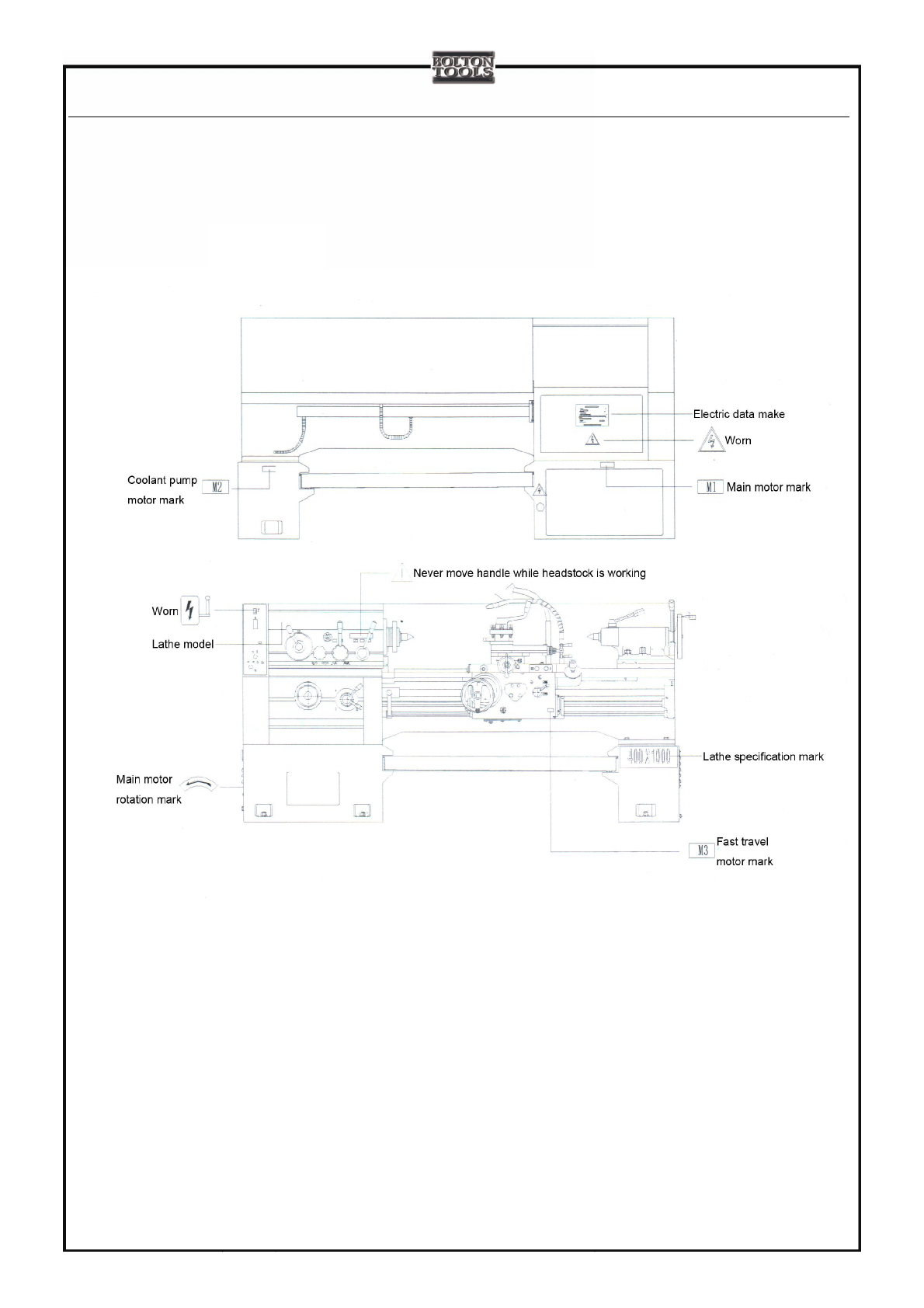
1.7 Drawing for Positions OfWarnsAnd Identifier
Fig. 1-3. Drawing for positions of warns and identifier

2.General Information
2-1
2.1 Notes:
2.1.1、Unpacking and inventory the accessories as packing list. Read and understand this manual and then hoist, install
the machine and test run accordingly.
2.1.2、Fix the 2 handles places in the accessories box to the carriage and apron in time, as well as the chip pan.(FIG
2-1)。
2.1.3 The manual is edited in accordance with latest product information, which may alter for
improvement purpose without any notice.
FIG.2-1. Installment of handle and chip pan

2.General Information
2-2
2.2 Main applications
2.2.1 General information
a. This machine is able to take operation like internal and external cylindrical turning, facing and other sort of
turnings; and is able to cut metric, inch, module and D.P. threads; to drill, ream, and broach grooves. In addition to that,
it is also suitable for flat-type and irregular-shaped work pieces turning.
b. The precision glass is up to 1T7 and roughness of work piece is to 1.6um.
c. This machine must be operated by trained and qualified persons
d. Work area
◆work temperature:5℃~40℃.
◆storage or in transportation:-20℃~60℃.
◆temperature change:1.1℃/min.
◆relative humidity:75%.
◆vibration:Below 0.5G.
◆avoid insolating in the sun or other place which the temperature is easily changeable.
◆avoid placing in the place of potentially volatile.
2.General Information
2-3
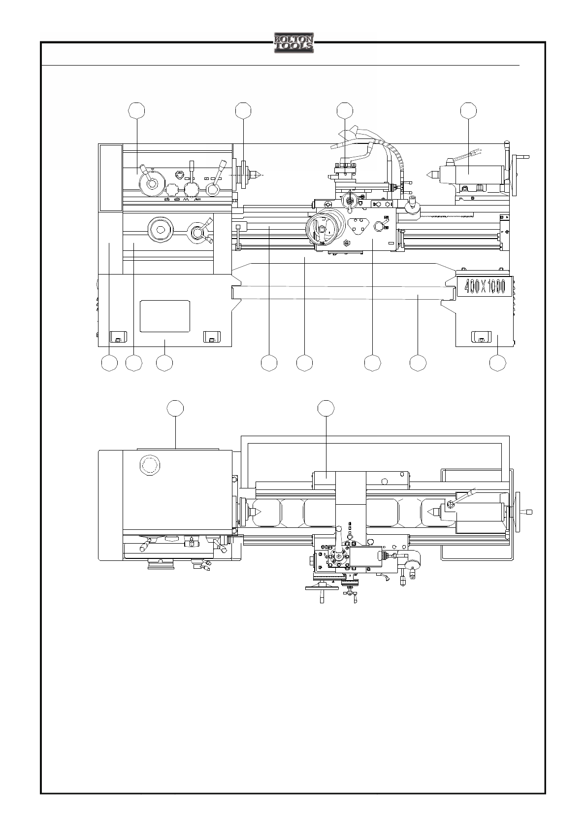
2.3 Identification
1. Heasstock 2.spindle 3.tool post 4.tailstock 5.gear box 6.feed box 7.front stand 8.lead screw 9.bed
10. Apron 11.chip pan 12.back stand 13.electrical cabinet 14.saddle
Fig.2-2.Main parts diagram
M3
2 3 4
6 7 8 9 10 11 12
1
13 14
5

3.Specification
3-1
3.1 Bed
3.1.1 Max. swing dia. Over bed 400 520 660 mm
3.1.2 Max. swing dia. in gap and available width of gap (only for gap-bed lathe)
640×220 760×220 900×220 mm
3.1.3 Max. workpiece length(five specifications) 750 1000 1500 2300 3000 mm
3.1.4 Max. turning length 650 900 1400 2200 2900 mm
3.2 Spindle
3.2.1 Distance between spindle to bed guideway 202 262 328 mm
3.2.2 Spindle bore
3.2.3 Spindle taper of the front bearing Metric 90
3.2.4 Spindle bore dia. φ82 mm
3.2.5 Spindle speeds
Number and range of forward speeds 12step 35-1600 rpm
Number and range of reverse speeds 6step 28-800 rpm
3.2.6 Spindle nose type C8
3.3 Tool post
3.3.1 Max. swing dia. over tool post 210 338 418 mm
3.3.2 Max. travel of tool post
Max. travel of lower tool post 260 320 340 mm
Max. travel of compound slide 120 mm
3.3.3 Swivel of tool rest ±45°
3.3.4 Distance from center axis to tool supporting surface 28mm
3.3.5 Tool-bar section 25×25mm
3.4 Tailstock
3.4.1 Tailstock sleeve dia. φ70mm
3.4.2 Tailstock sleeve travel
Longitudinal travel range of tailstock sleeve 150mm
Cross travel range of tailstock sleeve ±15mm
3.4.3 Bore taper of tailstock sleeve MT5
3.5 lead screw pitch
3.5.1 large lead screw pitch 12mm
3.5.2 middle lead screw pitch 5mm

3.Specification
3-2
3.6 Feeds
3.6.1 Feeds table
Model CE6
1
240B;CE6
1
252B;CE6
1
266B
Feeds Unit Metric/Inch
Number of longitudinal and cross feeds 131
Range of longitudinal feeds(mm)0.063-6.43
Range of cross feeds (mm) 0.027-0.60
3.6.2 Fast travel speed of apron(Longitudinal) 5.4m/min
3.6.3 Fast travel speed of apron(Cross) 1.9m/min
3.6.4 Number and range of threads
Model CE6
1
240B;CE6
1
252B;CE6
1
266B
Number of
threads Unit Metric/Inch
Kind 43
Metric Pitch range(mm)1-112
Kind 40
Inch Range(tooth/inch)1/4-28
Kind 38
Module Range(mm)0.5-56
Kind 41
D.P. Range(DP) 1/2-56
3.7 Motor
3.7.1 Type and power of main motor Y132S-4(5.5KW/7.5KW)
Rated speed of main motor 1440r/min
3.7.2 rapid travel motor model and power AOS—5634 250W
speed 1360r/min
3.7.3 coolant pump motor model and power DB—25A 90W
Flow 25 L.P.m
3.8 Power supply 380V, 50HZ(standar)
415V,60HZ; 220V,60HZ

3.Specification
3-3
3.9 Drive V-belt
Type and number of main drive V-belt B-2134, 2261,2286
Lubricating pump and number of drive v-belt O-900
3.10 General paramater
3.10.1 Net weight
Max. length of workpiece 750mm 2050 2150 2250kg
1000mm 2150 2250 2350kg
1500mm 2350 2450 2550kg
2300mm 2500 2600 2700kg
3000mm 2650 2750 2
3.10.2 Overall dimention(L × W × H)mm
Max. length of workpiece 750mm 2320×990×1250 2320×1040×1310 2320×1060×1380
1000mm 2570×990×1250 2570×1040×1310 2570×1060×1380
1500mm 3070×990×1250 3070×1040×1310 3070×1060×1380
2300mm 3870×990×1250 3870×1040×1310 3870×1060×1380
3000mm 4560×990×1250 4560×1040×1310 4560×1060×1380
850kg
4.Transmission systems
4-1
4.1 Main transmission systems
4.1.1 Transmission route (fig.4-1)
Spindle motion is transmitted to I axis in the headstock via belt wheel and V belt. There is a bi-directional disc friction
clutch, used to control the spindle and stop.
Clutch clamps (left) —gear 1-6 or 2-7—> II axel gains 2 grades forward rotation.
Clutch clamps (right) —middle gear—> II axel gains 1 grade reverse rotation.
3-linked sliding gear on III axel, engaged with state gear 8, 9 or 10, transmits the motion to III axel.Motion, then, will go
to VI axel from III axel through the following 2 ways:
a. Motion on III axel —Gear 14—>gear 27 on the left of VI axel (high speed transmission route)
b. Motion on III axel—gear 15-17—>VI axel—gear 18, 19—>V axel—gear 20—>gear 21 on the right of VI axel (low
speed transmission route)Two gears 21and 24 that is covered on VI axel (spindle) get connected with VI axel via clutch.
It will get 6 kinds of high speeds with 14-24 once clutch moves left, while 6 kinds of low speeds once right.
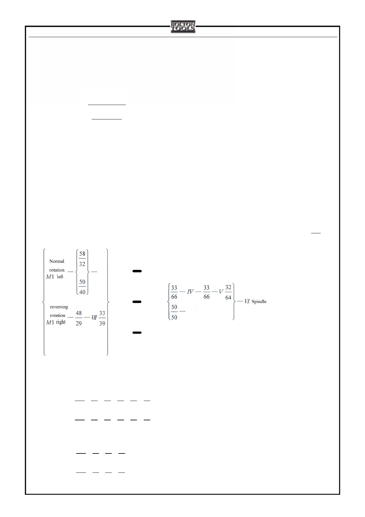
transmission route:
main motor—belt wheel(120
240 )
—Ⅰ—Ⅱ—
ïïïïï
þ
ïïïïï
ý
ü
ïïïïï
î
ïïïïï
í
ì
33
39
55
17
44
28
—Ⅲ—
1.1 4.1.2 calculation formula for spindle speeds (forward)
Here are the examples for the lowest and highest speeds of spindle.
●lowest speed
nmin=1440×120
240 ×50
40 ×17
55 ×33
66 ×33
66 ×32
64 =35r/min --------- 50HZ motor
nmin=1760×120
240 ×50
40 ×17
55 ×33
66 ×33
66 ×32
64 =42r/min --------- 60HZ motor
●highest speed
nmax=1440×120
240 ×58
32 ×39
33 ×50
50 =1600r/min--------- 50HZ motor
nmax=1760×120
240 ×58
32 ×39
33 ×50
50 =1900r/min--------- 60HZ motor
4.1.3 transmitting set of increasing pitch(Un):

4.
Transmission systems
4-2
This device is set into the headstock. That throw handle 4 (FIG 7-1) is the way to enlarger pitch or feeds.
Sliding gear 28 in headstock: there are left and right positions. Transmitting way from spindle Ⅵto Ⅷ:
Spindle Ⅵ—
ïï
þ
ïï
ý
ü
ïï
î
ïï
í
ì
50
50
33
66
33
66
32
64
50
50
—Ⅲ——Ⅳ——Ⅴ—
—
—Ⅷ
The ratio is 1 in the right while is 8 in the left. So the displacement is enlarged 8 times and it calls pitch-enlarging
transmission (to enlarge pitch or to increase feeds). When the spindle speed is 35~200r/min,pitch is enlarged 8 times.
4.1.4 Transmission unit for changing threads
There is a direction-changing device in the middle of shaft Ⅷand ⅩⅧ used to turning left and right threads. When
gear 32 of shaft ⅩⅧin the right, motion transmits from shaft Ⅷto shaft ⅩⅧ(26/26) directly to process dextrorotating
threads. While gear 32 in the left, motion transmits from shaft Ⅷvia ⅩⅦ to ⅩⅧ(
26
33
33
26 ´). The transmitting ratio is
not changed but the direction of shaft ⅩⅧ to process left rotating threads.
4.1.5 Change gear can realise three transmission ratio(Um):
Metric:
Under normal condition: 69
60 ×56
69
Processing inch 19T threads:69
60 ×57
69
Processing inch 11 2
1threads: 56
60 ×69
56
Inch:
Under normal condition: 114
82 ×81
114
Processing inch 19T threads:78
82 ×114
78
Processing inch 11 2
1threads: 114
82 ×78
114
4.2 Feeds transmission system
4.2.1 Transmission route (fig.4-1)
Feed rate is indicated by the spindle/rotation, dia. of cutting tools.
motion —gear 23-25 on spindle—>VIII axel or motion —gear 21-20 on spindle—>V axel—gear 18-19,17-15—>III
axel or —gear 26-28—>VIII axel—gear 28-29—>XVIII axel.
Then motion will go to feed box via change gear box of XVIII axel. Different route will be generated according to
process requirement.

4.Transmission systems
4-
3
4.2.2 According to the kind of thread changing transmission unit can be realised by operating handle 6 (see manual part 7
fig. 7-1). Besides it can be used for changing feed rate.
Up:Metric threads 27
28 ×30
27 module threads 27
28 ×29
41
Inch threads 41
30 ×30
27 pitch threads 41
30 ×29
41
4.2.3 Feed box basic speed changing unit (Ub)
The shaft Ⅰ,Ⅱ, and Ⅲin gear box are consists of a basic speed changing unit, which is realised by operating handle 7
(see manual part 7 fig. 7-1).
Ub:For metric and module threads total 7 units.They are
36
28 ×21
18 =3
2(handle position 1)32
28 ×21
18 =4
3(handle position 2)32
28 ×21
20 =6
5(handle position 4)
36
28 ×18
33 =12
11 (handle position 7)32
28 ×28
32 =1(handle position 8)32
28 ×28
36 =8
9(handle position 10)
18
21 ×21
21 =6
7(handle position 11)
For inch and pitch threads total 10 units.They are
18
21 ×28
36 =2
3(handle position 15)18
21 ×28
32 =3
4(handle position 14)21
21 ×28
36 =7
9(handle position13)
20
21 ×28
32 =5
6(handle position 12)32
28 ×28
36 =8
9(handle position 10)33
28 ×28
36 =11
12 (handle position 9)
32
28 ×28
32 =1 (handle position 8)36
28 ×28
32 =9
8(handle position 6)21
21 ×21
18 =7
6(handle position 5)
32
28 ×21
18 =4
3(handle position 2)
When calculating feed rate, it should be added below unit. They are total 15 units.
32
28 ×21
21 =9
7(handle position 3)
4.2.4 They are total 4 speed double increasing unit (Ud), which can be realised by operating handle 8(see manual part 7
fig. 7-1)
42
14 ×40
15 =8
1(handle positionⅠor A)42
14 ×32
24 =4
1(handle positionⅡor B)
42
14 ×22
33 =2
1(handle postion Ⅲor C)connecting of internal and external tooth 22
22 =1(handle position Ⅳor D)
4.2.5 leadscrew thread pitch:
Metric:T=12mm
Inch:T= 12.7mm (1/2 In)
4.3 Thread turning
4.3.1 Metric threads

4.
Transmission systems
4-4
From fomula 1×Un×26
33 ×33
26 ×Um×Up×Ub×Ud×T=TX (mm)
Can get TX=12× Un×Ub×Ud(mm)
4.3.2 Module threads
From fomula 1×Un×26
33 ×33
26 ×Um×Up×Ub×Ud×T=mπ
Can get m=6× Un×Ub×Ud(mm)
4.3.3 Inch threads
From fomula 1×Un×26
33 ×33
26 ×Um×Up×Ub×Ud×T=25.4
n
Can get n= 3
Un×Ub×Ud(threads/inch)
4.3.4 Diametric threads
From fomula 1×Un×26
33 ×33
26 ×Um×Up×Ub×Ud×T=25.4
DP ×π
Can get DP= 6
Un×Ub×Ud(tooth/inch)
4.3.5 Un-standard pitch threads
Joint tooth-typed clutch M1、M2、M3, and link input shaft and leas screw. According to different T values, you can
get teeth numbers of 4 gears and then calculate the threads.
4.4 Calculations of mechanical feeds
4.4.1 Methods of tool post’s longitudinal travel
a. if turn inner and outer column surfaces, motion joggles with small gear 83 via feed box, rod screw, apron etc and
rotate. Then apron drives tool post to have the longitudinal feeds.
b.Turning threads, motion goes through feed box, lead screw, and half nut 94 and drives the tool post to have
longitudinal threads turning feeds.
c.Rotate hand wheel on apron, small gear 83 and rack 84 joggles. Hand wheel brings apron to have the longitudinal
travel.
d.Model CE61
240B;CE61
252B;CE61
266B with rapid travel motor. Start motor and apron which drives tool post
makes the action of longitudinal travel.
4.4.2 Methods of tool post’s cross travel
a.If turning the surfaces, motion that is via feed box and apron drives gears on lower tool post screw 92(or 115), cross
feeds begins.
b.Rotate the handle of lower tool post.

4.Transmission systems
4-5
c.Model CE61
240B;CE61
252B;CE61
266B,start the motor and the cross fast travel begins.
4.4.3 Feed rate calculation
The feed rate per each rotation of spidle can get from below fomula:
S longitudinal =1×Un×Um×Up×Ub×Ud×Ufeed rod×Uapron longitudinal×π×m×Z(mm/r)
S cross =1×Un×Um×Up×Ub×Ud×Ufeed rod×Uapron cross×t(mm/r)
In the above fomula:Ufeed rod=21
42 =1
2
Uapron longitudinal =36
32 ×32
56 × 2
26 ×32
36 ×45
87
Uapron cross=36
32 ×32
56 × 2
26 ×32
36 ×45
35 ×58
18
m=2.5mm moudulus of apron rack shaft
Z=12 teeth of apron rack shaft
Metric :t=5 mm thread pitch of middle lead screw
Inch: t=1/4 In
! note: choose proper feeds and turning depth, or it may cause damager to tools and human.
4.
Transmission systems
4-6
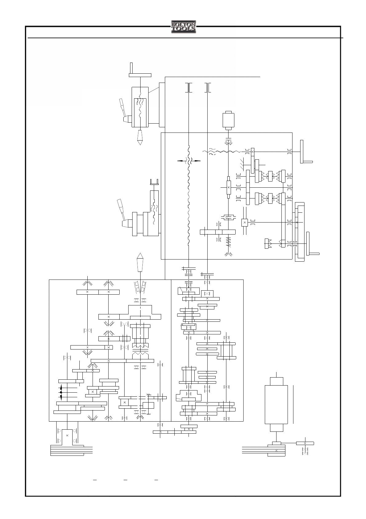
4.5 Transmitting system diagram
Fig. 4-1.CE61
240B;CE61
252B;CE61
266B transmitting system diagram of left hand wheel apron
M2 M3
1440r/min
Y132S-45.5/7.5KW
83
M1
65
64
63
62
61
60
59
58
5756
55
54
5352
515049
484746
45
44
43
40
39
4241
3837
35
34
33
29
28
2726
24
M1
M2
16
15
25
23
21
22
19
20
18
8685
70
80
77
17
4
12
93
81
79
78 88
7472 73
36
Ⅷ
Ⅲ
Ⅱ
82
76
69
71
98
97
Ⅵ
Ⅴ
92
91
94
96
95
75
84
89 90
87
ⅩⅧ
Ⅶ
ⅩⅦ
Ⅳ
Ⅰ
11
13
14
10
9
8
7
6
5
3
2
1
4.Transmission systems
4-
7
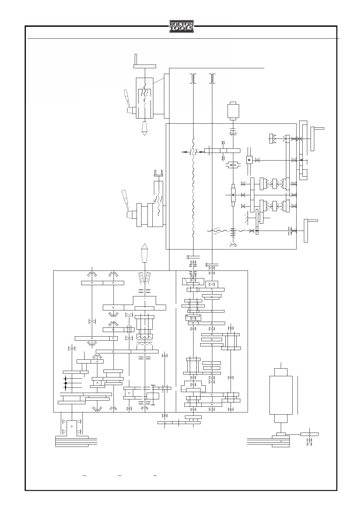
Fig. 4-2.CE61
240B/2;CE61
252B/2;CE61
266B/2 transmitting system diagram of right hand wheel apron
95 96
94
97
98
93
81
88
747372
84
86
87 85
8277
79
80
78
90 89
83
76
75
71
70
69
123
5
67
8910
14
13
11
Ⅰ
ⅩⅦ
Ⅶ
ⅩⅧ
1440r/min
Ⅴ
Y132S-45.5KW
Ⅱ
Ⅲ
Ⅷ12
4
17 18
20
19
22
21
23
25
15
16
M2
M1
24
26 27
28
29
Ⅵ
Ⅳ
35
34
33
36
64
62
615756
5352
484746
40
39
4241
M2 M3
M1
54
515049
45
44
43
3837 65
63
605855 59
91
92
Other Bolton Tools Lathe manuals


