LOBSTER ARF-810E User manual

CONTENTS
英語/ENGLISH
ARF-810E
INTRODUCTION…………………………… 1
IMPORTANT SAFETY INSTRUCTIONS… 2
NOMENCLATURE……………………… 6
TECHNICAL DATA………………………… 7
PREPARATION BEFORE USE…………1 0
HOW TO OPERATE………………………11
CHANGE SIZE OF RIVETS………………13
CHANGE OF THE RIVETER USED……15
MAINTENANCE………………………… 1 6
ORDERING PARTS……………………… 1 6
TROUBLESHOOTING………………… 1 7
PARTS TABLE…………………………… 1 8
MODEL CHANGE AND PARTS LIST…22
AUTO RIVET FEEDER
AIR RIVETER
INSTRUCTION MANUAL
Professional
model
of
air
riveter
to
install
blind
rivets.
Thank you very much for purchasing “LOBSTER” air riveter. To ensure correct operation, please read
this instruction manual carefully, and keep it in a safe place for later reference.
CONTENTS
IMPORTANT
SAFETY
INSTRUCTIONS.................................1
NOMENCLATURE .............................3
TECHNICAL
DATA ...........................4
PREPARATION
BEFORE
USE .......5
OPERATING
THE
AIR
RIVETER ....7
MAINTENANCE .................................8
STORAGE........................................12
TROUBLESHOOTING .....................15
PARTS
TABLE ................................13
ORDERING
PARTS .........................14
MANUFACTURER
PRINTED IN JAPAN
英語/ENGLISH
BUILT-IN ON-DEMAND
VACUUM SYSTEM
R1A1
INSTRUCTION MANUAL
Professional model of auto rivet feeder to install blind rivets.
・Thank you very much for purchasing “LOBSTER” auto rivet feeder. To ensure correct operation,
please carefully read this instruction manual and keep it in a safe place for later reference.
・This is Original instructions.
Osaka 579-8053, Japan
12-8 Shijo-cho, Higashi-Osaka City
Telephone: +81(72)981-7466 Telefacs: +81(72)981-9420
URL https://www.lobtex.co.jp/
MANUFACTURER
International Marketing & Sales Division
AIR RIVETER
INSTRUCTION MANUAL
Professional
model
of
air
riveter
to
install
blind
rivets.
Thank you very much for purchasing “LOBSTER” air riveter. To ensure correct operation, please read
this instruction manual carefully, and keep it in a safe place for later reference.
CONTENTS
IMPORTANT
SAFETY
INSTRUCTIONS.................................1
NOMENCLATURE .............................3
TECHNICAL
DATA ...........................4
PREPARATION
BEFORE
USE .......5
OPERATING
THE
AIR
RIVETER ....7
MAINTENANCE .................................8
STORAGE........................................12
TROUBLESHOOTING .....................15
PARTS
TABLE ................................13
ORDERING
PARTS .........................14
MANUFACTURER
PRINTED IN JAPAN
英語/ENGLISH
BUILT-IN ON-DEMAND
VACUUM SYSTEM
R1A1
PRINTED IN JAPAN No .AF810ES11000

英語/ENGLISH
1
● INTRODUCTION
・This is the feeder for "LOBSTER" brand blind rivet which can be used with "LOBSTER" brand
riveter. It is not designed, produced or sold for any other purpose.
・This instruction manual shows how to operate and perform maintenance and inspection in
order to use safely and efficiently.
・ Use appropriate blind rivet which is fully designed and meets specications.
1
1
1
2
・Our warranty does not apply to direct and indirect damages and lost income caused by the
misuse, abuse, and unauthorized modification of the machine.
We do not guarantee the strength or quality of blind rivet.
・We do not guarantee any damages and failures caused by any modifications without our
written approval.
・We do not guarantee any damages and failures caused by use of parts other than our
recommendation.
IMPORTANT NOTICES
INDEMNIFICATION
・Read this manual carefully before using this machine. Follow instructions in this manual for
handling this machine, replacing accessories or parts as needed.
・If you have any questions, check the model (type)and contact the
“LOBSTER” dealer where you purchased the machine.
・It is impossible to foresee all potential dangers and describe them in this manual.
You must use this machine paying attention to safety as well as observing the instructions
in this manual.
・Lobtex Co., Ltd. has the copyright of this manual. It is prohibited to publish, copy or translate
to other language without prior consent.

2
英語/ENGLISH
◆Be sure to read the following Important Safety Instructions carefully and make sure that you
understand them thoroughly before using this machine.
1.Always wear protective goggles while you use the machine.
・The rivets may jump out by accident and cause injuries (e.g. blindness).
・Use a dust mask, safety shoes, hard hat and hearing protector appropriately to prevent accidents
and injuries.
2.Make sure that the machine and the power cable are connected securely.
3. Prior to use, check for damage to respective parts, and ensure that all parts are able to operate
normally and provide the functions specified. If they are unable to operate normally or provide the
functions specified, do not use them, but arrange for a repair by a competent person.
・ If the machine is used while any parts are damaged, injury may result.
・If the machine is damaged by objects being dropped onto it, the damaged part may break and
accident or injury may result.
・ When replacing or cleaning parts, observe the instructions in the instruction manual.
If you cannot nd the relevant instructions in the manual, arrange to have arepair carried out by
the supplier you purchased the product from, or by Lobtex.
・ If there is no power to the equipment even though the power switch is turned on, or the machine
cannot be started when the start button is pressed, do not use the machine.
Otherwise, it may operate abnormally, causing injuries.
4.Install and use on a stable work table that is horizontal and free from vibration.
・ Otherwise, the machine may not be able to achieve performance as specied, or it may be
dislodged, leading to breakage, injury, or damage.
・If you install it on the oor, there is a risk that people may step on it.
5.Keep the machine away from children.
・ Accidents or injury may result.
6.Do not use the machine in rain or in a wet place.
・ Accidents or injury may result.
1
日本語/JAPANESE
安全上のご注意
◆ご使用前に、この「安全上のご注意」すべてをよくお読みのうえ、十分理解されて正しく使用して
ください。
◆本機をご使用中は、必ず保護めがねを着用してください。切断されたリベットのマンドレルが飛び
出し傷害を及ぼす恐れがあります。
◆ここに示した注意事項は と に区分けしていますが、それぞれの意味は下記の通りです。
t警 告 t注 意
:誤った取扱いをした場合、使用者が死亡または重傷を負う可能性が想定される内容
のご注意
:誤った取扱いをした場合、使用者が傷害を負う可能性が想定される場合、及び物的
損害のみの発生が想定される内容のご注意
なお、 に記載した事項でも重大な結果に結び付く可能性があります。いずれも安全
に関する重要な内容を記載していますので、必ず守ってください。
t注 意
1. 使用空気圧0.49〜0.59MPa(5〜6kgf/cm2)を守ってください。
¡使用空気圧を超えて使用しますと、本機が破損して傷害や損傷を及ぼす恐れがあります。
2. 必ず安全カバーを取り付けてお使いください。
¡切断されたリベットのマンドレルが飛び出し傷害を及ぼす恐れがあります。
3. シリンダー部からの給油の際は必ずフレームヘッドをはずしてください。
¡フレームヘッドをはずさずに給油すると余分な油圧オイルが入り、本機が破損してけがをする恐れ
があります。(油止めネジ部からの給油はのぞく)
4. 本機とエアー源との接続は確実に行なってください。
¡ジョイントのネジが合わなかったり、ネジの入りしろが不十分であった場合、使用中にエアーホー
スがはずれてけがをする恐れがあります。
¡エアーホースジョイントとエアーホースの接続はホースバンドを用いて確実に行なってください。
接続が不十分ですと使用中にエアーホースがはずれてけがをする恐れがあります。
5. 本機をエアー源からはずす時は、エアーの供給を止めてください。
¡圧縮空気によりエアーホースが跳ねたりして、けがをする恐れがあります。
6. ご使用前に各部の損傷がないかをチェックし、損傷がある場合は、使用せずに修理に出して
ください。
¡損傷がありながら使用しますとけがをする恐れがあります。
¡物を落とすなどしてホースに傷等が生じますと、その部分が破損して事故やけがの原因になります。
¡工アーホースを持って本機を引きするなどしますと、本体に傷が生じたり、二ツプルが破損したり、
その他作動不具合が生じたりして、事故やけがをする恐れがあります。
~~~~~~~~~~~~~
~~~~~~~~~~~~~~
◆お読みになった後は、お使いになる方がいつでも見られる所に必ず保管してください。
t警 告
t注 意
t警 告
AR-2000S-M-H(A)取扱(日):AR-2000S_M-H(A)取扱(日) 14/08/25 11:49 ページ 1
◆Do not put your hands in the machine or close to the moving parts while you are using the
machine. Otherwise your hand may be caught and injury may result.
● IMPORTANT SAFETY INSTRUCTIONS
◆After reading this manual, keep it in a safe place where it is easily accessible to machine users.
IMPORTANT
SAFETY
INSTRUCTIONS
◆ Be sure to read the following Important Safety Instructions carefully and make sure that you
understand them thoroughly before using this tool.
◆ Always wear eye-protection at all times during use. If this is not observed, the cut mandrels
may eject out when the rivets are cut and cause serious injury.
◆ This is the safety alert symbol. It is used to alert you to potential personal injury hazards.
Obey all safety messages that follow this symbol to avoid possible injury or death.
◆ The Important Safety Instructions are divided into and .
The differences between these two levels are described below.
CAUTION
WARNING
: Indicates a potentially hazardous situation which, if not avoided, could result in death or
serious injury to the operator.
: Indicates a potentially hazardous situation which, if not avoided, may result in moderate
injury to the operator or physical damage.
Moreover, failure to follow the instructions marked with the symbol or cautions without a
symbol which appear in the text of this manual may also have serious results in some cases.
Always be sure to observe the instructions given in the Important Safety Instructions.
CAUTION
CAUTION
CAUTION
WARNING
1.
The
air
pressure
should
be
kept
within
the
range
of
0.49
to
0.59
MPa
(5
to
6
kgf/cm2,
71
to
85
psi).
If an air pressure which is greater than this is used, the tool may become damaged, and injury or
damage to property may result.
2.
Never
look
into
the
nosepiece
of
the
tool,
and
never
point
the
nosepiece
toward
other
persons.
If the tool is used while the cut mandrels are still inside the tool not being ejected, these mandrels may
be ejected from the tool’s nosepiece during use and cause serious injury.
3. Always
attach
the
tank case
unit
before
use.
If this is not observed, the cut mandrels may be ejected when the rivets are cut and cause serious
injury.
4. Wear
protective
glasses
during
use.
Failure to do so may result in an accident or personal injury in case that a rivet or a piece of cut-mandrels
jumps out toward you.
5. Make
sure
that
the
tool
and
the
air
source
are
connected
securely.
If the threads of the joints do not match or if the screws are not inserted far enough, the air hose may
become disconnected during use and injury may result.
Use hose bands to securely connect the air hose joint and air hose. If they are not connected securely
enough, the air hose may become disconnected during use and injury may result.
6. Turn
off
the
air
supply
before
disconnecting
the
tool
from
the
air
source.
Compressed air may cause the air hose to whip around, and injury may result.
7. Check
that
all
the
tool
parts
are
free
from
damage
before
use.
Any
damaged
parts
should
be
repaired
before
the
tool
is
used.
If the tool is used while any parts are still damaged, injury may result.
If the tool is damaged by objects being dropped onto it, for instance, the damaged part may break and
accident or injury may result.
Don't pull and drag the tool by the air hose. It may trigger some damages on the tool body, breakage of
Rotary Joint or some other defects and lead serious troubles with injuries.
8. If
using
in
elevated
locations,
use
a
safety
harness,
and
take
care
to
avoid
dropping
rivets
or
the
tool
itself.
Accident or injury may result if this practice is not followed.
◆ After reading this manual, keep it in a safe place where it is easily accessible to tool users.
WARNING
英語/ENGLISH
1
1. Before
starting
maintenance
or
disassembling
the
unit
to
replace
parts,
be
sure
to
stop
air
supply.
Performing maintenance or disassembly with air supplied may cause a part to jump out, oil to squirt out,
or the unit to perform unexpected behavior, and may result in an accident or personal injury.
3.
2.
Do
not
operate
the
tool
with
the
Frame
Head ‘CJM’
removed .
Tighten
the
Bleed
Plug
firmly
before
use.
Items such as fingers may become caught in the mechanism.
If the Bleed Plug is loose or coming off during use, oil may squirt out resulting in an accident or personal
injury.
4. Do
not
bring
your
face
close
to
the
air
outlet
holes.
Pressurized air containing fine particles is discharged from the air outlet holes during use. Keep eyes
away from this area.
5. Avoid
skin
contact
with
substances
such
as
hydraulic
oil,
lubricating
oil
and
grease.
Such substances may cause inflammation of the skin. If they come into contact with your skin, wash
the affected area thoroughly.
6. The
parts
to
be
used
must
be
those
supplied
from
us
or
recommended
by
us.
Select
and
attach
parts
applicable
to
your
rivet.
Otherwise the unit may not produce maximum performance and may sometimes malfunction resulting
in an accident or personal injury.
7. Make
sure
that
the
workplace
is
safe,
clean
and
organized.
Accidents can easily occur in untidy workplaces.
If the cut-mandrels are allowed to fall onto the floor, you may slip on them, and injury may result.
8. Avoid
uncomfortable
postures
while
working.
You may fall down and injury may result.
9. Keep
people
who
are
not
involved
in
work
away
from
the
workplace.
Accidents or injury may result.
10. Maintain
the
tool
with
due
care.
Refer to the Instruction Manual for details on replacing parts and attachments, otherwise injury may occur.
11. Keep
the
handgrip
always
dry
and
clean,
and
avoid
adhesion
of
oil
and
grease.
Otherwise the grip may slip from your hand resulting in falling of the unit.
12. Do
not
leave
the
floor
littered
with
cut-mandrels.
Cut-mandrels are dangerous because their ends are sharp. Stepping on them is also dangerous easily
causing a slip and fall accident.
13. Use
the
tool
carefully
and
concentrate
on
correct
operation
at
all
times.
Use the tool with proper care, paying full attention to methods of handling and operation and
surrounding conditions. Accidents and injury may result if this practice is not followed.
Use common sense at all times, otherwise accidents or injury may result.
When you are tired, do not use the tool, otherwise accidents or injury may result.
14.
Ask
Lobtex
to
carry
out
any
repair
work
required.
Repair work should only be carried out by a qualified technician. Please contact your nearest
“LOBSTER” distributor, representative, or direct to Lobtex Co., Ltd., Osaka. If the tool is repaired by
someone without the necessary qualifications and experience, the tool may not perform to optimum
standards, and accidents or injury may result.
15.
Do
not
attempt
to
modify
the
tool.
Unauthorized modifications may cause malfunctions which can lead to accidents or injury.
16.
Only
for
EU
countries,
do
not
dispose
of
electric
tools
together
with
household
waste
material
!
In observance of European Directive 2002/96/EC on waste electrical and electronic equipment and
its implementation in accordance with national law, electric tools that have reached the end of their
life must be collected separately and returned to an environmentally compatible recycling facility.
CAUTION
英語/ENGLISH
2
◆This is the safety alert symbol. It is used to alert you to potential personal injury hazards.
Obey all safety messages that follow this symbol to avoid possible injury or death.
◆Always wear protective goggles while using the machine.
The rivets may jump out by accident and cause injuries.
◆These Important Safety Instructions are divided into and .
The dierences between these two levels are described below.
: Indicates a potentially hazardous situation which, if ignored, may result in death
or serious injury to the operator.
: Indicates a potentially hazardous situation which, if ignored, may result in moderate
injury to the operator or physical damage.
Moreover, failure to follow the instructions marked with the symbol or cautions without a
symbol which appear in the text of this manual may also have serious results in some
cases. Always be sure to observe the instructions given in the lmportant Safety Instructions.
⚠WARNING
⚠WARNING
⚠CAUTION
⚠CAUTION
⚠CAUTION
⚠CAUTION
⚠WARNING
1
日本語/JAPANESE
安全上のご注意
◆ご使用前に、この「安全上のご注意」すべてをよくお読みのうえ、十分理解されて正しく使用して
ください。
◆本機をご使用中は、必ず保護めがねを着用してください。切断されたリベットのマンドレルが飛び
出し傷害を及ぼす恐れがあります。
◆ここに示した注意事項は と に区分けしていますが、それぞれの意味は下記の通りです。
t警 告 t注 意
:誤った取扱いをした場合、使用者が死亡または重傷を負う可能性が想定される内容
のご注意
:誤った取扱いをした場合、使用者が傷害を負う可能性が想定される場合、及び物的
損害のみの発生が想定される内容のご注意
なお、 に記載した事項でも重大な結果に結び付く可能性があります。いずれも安全
に関する重要な内容を記載していますので、必ず守ってください。
t注 意
1. 使用空気圧0.49〜0.59MPa(5〜6kgf/cm2)を守ってください。
¡使用空気圧を超えて使用しますと、本機が破損して傷害や損傷を及ぼす恐れがあります。
2. 必ず安全カバーを取り付けてお使いください。
¡切断されたリベットのマンドレルが飛び出し傷害を及ぼす恐れがあります。
3. シリンダー部からの給油の際は必ずフレームヘッドをはずしてください。
¡フレームヘッドをはずさずに給油すると余分な油圧オイルが入り、本機が破損してけがをする恐れ
があります。(油止めネジ部からの給油はのぞく)
4. 本機とエアー源との接続は確実に行なってください。
¡ジョイントのネジが合わなかったり、ネジの入りしろが不十分であった場合、使用中にエアーホー
スがはずれてけがをする恐れがあります。
¡エアーホースジョイントとエアーホースの接続はホースバンドを用いて確実に行なってください。
接続が不十分ですと使用中にエアーホースがはずれてけがをする恐れがあります。
5. 本機をエアー源からはずす時は、エアーの供給を止めてください。
¡圧縮空気によりエアーホースが跳ねたりして、けがをする恐れがあります。
6. ご使用前に各部の損傷がないかをチェックし、損傷がある場合は、使用せずに修理に出して
ください。
¡損傷がありながら使用しますとけがをする恐れがあります。
¡物を落とすなどしてホースに傷等が生じますと、その部分が破損して事故やけがの原因になります。
¡工アーホースを持って本機を引きするなどしますと、本体に傷が生じたり、二ツプルが破損したり、
その他作動不具合が生じたりして、事故やけがをする恐れがあります。
~~~~~~~~~~~~~
~~~~~~~~~~~~~~
◆お読みになった後は、お使いになる方がいつでも見られる所に必ず保管してください。
t警 告
t注 意
t警 告
AR-2000S-M-H(A)取扱(日):AR-2000S_M-H(A)取扱(日) 14/08/25 11:49 ページ 1

1.Before starting maintenance or disassembling the unit to replace part, be sure to take off
power cable.
・ By unexpected action such like parts jumps out may cause accidents.
2.When you handle grease, obtain the safety data sheet (SDS) from the supplier, and follow the
described instructions.
3.The parts to be used must be those supplied from Lobtex or recommended by Lobtex.
Select and attach parts applicable to your rivet.
・ Otherwise the unit may not produce maximum performance and may malfunction resulting in an
accident or personal injury.
4.Make sure that the workplace is safe, clean and organized.
・ Accidents can easily occur in untidy workplaces.
5.Ensure sound footing and do not work in an unnatural posture.
・ You may fall and injure yourself.
6.Keep people who are not involved in work away from the workplace.
・ Accidents or injury may result.
7.Avoid a sudden start of the machine. Before connecting it to the power supply, confirm that the
switch is not turned on.
8.When replacing parts or accessories, follow the steps specified.
9.Be sure to use the provided AC adapter for the power supply.
10.Wear clothes appropriate for work. Cover long hair with a cap or hair cover.
Do not wear loose clothes or accessories including necklaces.
・ Otherwise, your hair, clothes, or accessories may be caught in the machine.
11.Do not use the machine if it cannot be started or stopped using its switches.
・ Otherwise, it may operate abnormally, leading to injuries. Arrange for a repair by a competent
person.
12.Keep the machine away from children. Prevent anyone except for workers from touching a power
cable or the machine.
・ Otherwise, it may lead to injuries.
13.Check thoroughly for damage to the machine. If any loose or damage to parts are found, do not
use the machine, but arrange for a repair by a competent person.
・ Failure to perform this step may lead to accidents or injuries due to malfunctions.
14.Use specified accessories or replacement parts only.
・ Otherwise, unexpected motion of the machine may be caused, leading to accidents or injuries.
15.Be sure to turn off the power before performing work such as changing the rivet size.
16.Never put your hand inside the rotating drum
・Otherwise, unexpected motion of the machine may be caused, leading to accidents or injuries.
・ Be sure to take out the remaining rivets by riveter supply
17.Do not intentionally press the switch that is pressed by opening and closing the lid (rivet slot).
18.Use specified genuine parts only, and only allow persons having technical knowledge and skills to
repair the machine.
・ If no such competent person is available, arrange to have a repair carried out by the supplier
you purchased the product from or by Lobtex.
19.If the machine is faulty or any abnormal noise is heard while in use, immediately turn off the switch
to stop it, and arrange to have a repair carried out by the supplier you purchased the product from
or by Lobtex.
・ Continued use of the equipment may cause injuries.
3
英語/ENGLISH
⚠WARNING
⚠CAUTION

7.Maintain the machine with proper care.
・ Refer to the Instruction Manual for details on replacing parts and attachments, otherwise injury
may occur.
8.Use the machine carefully and concentrate on correct operation at all times.
・ Use the machine with proper care, paying full attention to methods of handing and operation and
surrounding conditions. Accidents and injury may result if this practice is not followed.
・ Use common sense at all times, otherwise accidents or injury may result.
・ When you are tired, do not use the machine, otherwise accidents or injury may result.
9.Ask Lobtex to carry out any repair work required.
・ If you nd any fault, arrange to have an inspection and a repair.
・ Repair work should only be carried out by a qualified technician. Please contact your nearest
“LOBSTER” distributor, representative, or direct to Lobtex Co.,Ltd.,Osaka. If the machine is
repaired by someone without the necessary qualifications and experience, the machine may
not perform to optimum standards, and accidents or injury may result.
10.Do not modify the machine. Any modification to the equipment impairs the validity of safety devices
leading to a higher risk to operators.
・ This machine conforms to applicable safety standards. Do not modify it.
Otherwise, accidents or injuries caused by abnormal operation may occur.
11.When disposing of the machine or packing materials, observe local laws and codes on waste
disposal.
12.The year and month of production of the machine is indicated by a code and four-digit number on
the warning seal. (See page 6)
13.Warning seal include important information and tips on using the machine. If the labels become so
dirty or damaged that they cannot be read, order and replace them with new labels.
You can order new labels from Lobtex Co., Ltd. through our dealers.
14.This machine is a feeder for professional use. Operators who use it for the first time must
understand its instruction manual completely before maintaining or using the machine.
・ If the machine is broken, do not operate.
15.Slips, trips and falls are major causes of injury at workplace. Be aware of trip hazards caused by
power cable.
16.This machine is not intended for use in potentially explosive atmospheres and is not insulated
against contact with electric power.
17.Preventative maintenance should be carried out, after a specified time of operation, a specified
number of cycles/operations or a stated number of times per year.
18.Store the machine appropriately when not in use.
・ Store it in a dry and high place where it can be locked away or is out of the reach of children.
Otherwise, it may cause injury.
19.Do not use more than ability.
・ Use the equipment according to the capacity of the machine and in accordance with its design
specication. Use of the machine incorrectly may lead to accidents.
20.Do not handle any power cable roughly.
・ Do not pull the power cable to remove it from the receptacle outlet.
・ Keep the power cable away from heat, oil, and sharp edges.
・ Pay close attention to prevent the power cable from being stepped on, hooked, or damaged by
the use of excessive force. Otherwise, it may cause an electric shock or a short-circuit, leading to
re.
英語/ENGLISH
4
⚠CAUTION

英語/ENGLISH
5
21.Check for damage to respective parts prior to use and arrange for a repair by a competent person
if any damage is found.
・ Check thoroughly for damage to respective parts prior to use and ensure that the machine
operates normally and the specied functions can be provided.
・ When replacing or cleaning parts, observe the instructions in the instruction manual. If you cannot
nd them in the manual, arrange to have a repair carried out by the supplier you purchased the
product from, or by Lobtex.
・ If there is no power to the equipment even though the power switch is turned on, or the machine
cannot be started when the start button is pressed, do not use the machine.
Otherwise, it may operate abnormally, causing injuries.
22.If you find rust, or experience unusual odor, heat, or other abnormalities when using the machine
for the first time after purchase, do not use it, but contact the supplier you purchased the product
from, or contact Lobtex.
23.Keep your fingers away from around the rotating shaft or the inside of the machine.
・ Otherwise, your ngers may be caught, causing injury.
24.Using the machine repeatedly may cause fatigue in your hands, shoulders, neck, and other locations.
・ To avoid pain and fatigue, assume an appropriate and natural posture, and change your
posture as necessary.
・ If you suer from continuous discomfort, pain, numbness, palpitations, stiness, or hot
flashes, do not ignore it. Consult with your employer and health manager.
⚠CAUTION

6
英語/ENGLISH
■ ACCESSORIES ■ Check at the time of purchase
・Easy guide
・AC adapter AIKOH ELECTRONICS CORP. AKA-12030 (Input AC100-240V Output 12V 3.0A)
・Tweezers
◇ Substance
◇ Front panel (operation buttons)
Start button
Power switch
Count display
LED(green) LED(red)
Button(Λ) Button(>) Reset button
Lock button Lock button
Power entry point External output
Warning seal
Supply port
(Frame Head Holder)
Front panel
Cover unit
Rivet slot
● NOMENCLATURE
・ Power Cable

Operating voltage DC 12V
Current consumption Below 1. 5A
Dimensions (Length×Height×Width)420mm ×350mm ×240mm
Weight 10.5kg
Operation-guaranteed
environment
Temperature 5~40℃
Relative humidity 80%RH max (No condensation)
Storage temperature range - 5~55℃
Noise 75dB or less
Cycle time 3min/pcs.
Basket capacity 1000pcs. (φ2.4 ・ φ3.2) ・ 500pcs. (φ4.0)
Frame head insertion port dia 21mm ・ 23mm
英語/ENGLISH
7
◇ MODEL
◇ Product specication
*Product specifications and design are subject to change for improvement without notice.
*Weight and dimensions given are standard values. Actual products may dier slightly from the
values given.
*The rating plate (warning plate attaching location) is on the back side of the machine.
*The year and month of production of the machine is indicated by a code and four-digit numbers.
*Measured at equivalent noise measurement level.
*Be careful not to exceed the basket capacity. If it is exceeded, it may cause a malfunction.
*When using a retaining Nosepiece, if a spent mandrel protrudes from it after riveting, you may not
pick up a rivet. Then push the rivet into the Nosepiece so that you can pick it up.
Frame head
holder diameter
21 21mm
23 23mm
Rivet diameter
24 2.4mm (Type 3)
32 3.2mm (Type 4)
40 4.0mm (Type 5)
ARF-810E-□-□
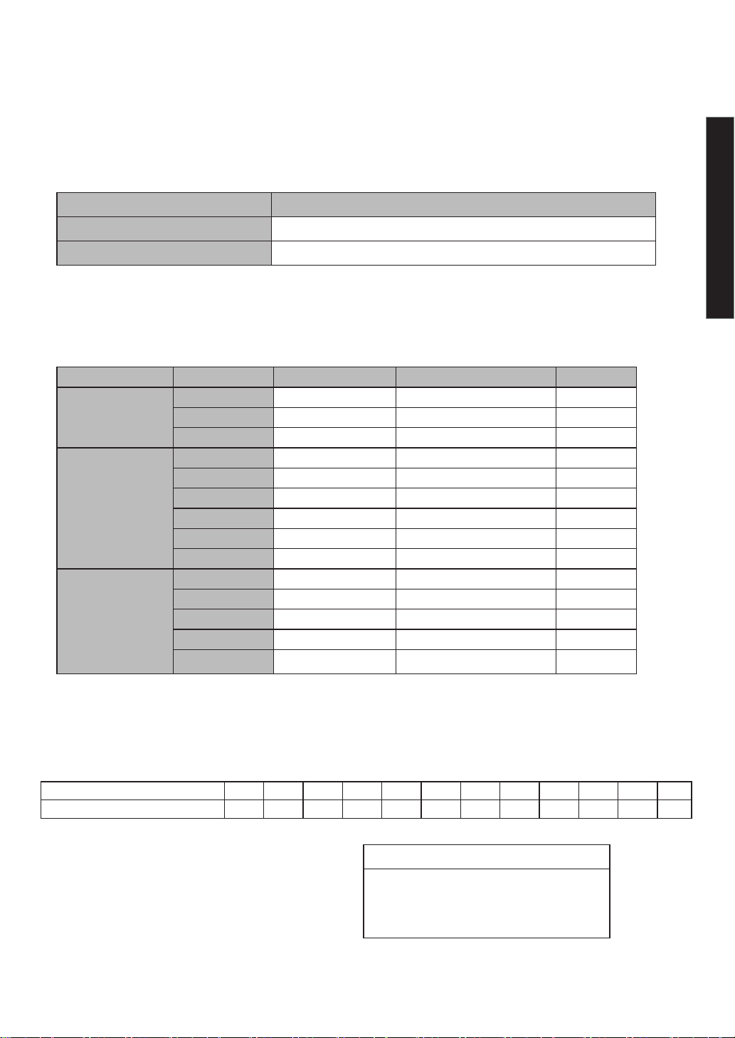
◇ Operating modes
Count display Operating modes Function
Total Count Mode
(TCNT)
Count the number of times rivet is picked up, which starts
from 0000.
Preset Count Mode
(PSET)
Count down the number of rivet you picked up, which starts
from the preset number. When coming down to 0000, the
number returns to preset number.
No-Count Mode
(NCNT)No counting. The display always shows "_ _ _ _ "
● TECHNICAL DATA
8
英語/ENGLISH
Rivet diameter Rivet size Round head rivet Countersunk head rivet AP rivet
φ2.4
3-2 ○ ○ 一
3-3 ○ ○ 一
3-4 ○ ○ 一
φ3.2
4-1 ○ 一 一
4-2 ○ ○ 一
4-3 ○ ○ ○
4-4 ○ ○ 一
4-5 ○ ○ ○
4-6 ○ ○ 一
φ4.0
5-2 ○ ○ 一
5-3 ○ ○ 一
5-4 ○ ○ ○
5-5 ○ ○ 一
5-6 ○ ○ 一
◇ Applicable riveter
Use R2B1 ・ R2A1 ・ R1A1 ・ AR2000MV ・ ARV011M ・
ARV015MX ・
ARV022M
ARV025M (can be used without vacuum function when using Retaining Nosepiece)
Use NSA・NTA・NA・NST・NSS・NS・AP・LST・or LSS For rivet sizes, see the list below.
*Do not insert anything other than the blind rivet to be used into the rivet slot (see P6).
*Use a riveter appropriate for the frame head holder.If dierent-size Frame Head is used, it does not
work properly.
Diameter of Frame Head Applicable riveter
21 R2B1 ・ R2A1 ・ R1A1 ・ AR2000MV
23 ARV011M ・ ARV015MX ・ ARV022M ・ ARV025M
◇ Rivet size
◇ How to read the year and month of production
Revision history of instruction manual
Item :Auto rivet feeder
Model : ARF-810E
Date of first edition: March 2023
M N
a year/month of manufucture 1 2 3 4 5 6 7 8 9 10 11 12
An English character A B M N K W T Y U O L Z
Exsample
year: 2023 month: 4 → BMN○○○○
↓ ↓ ↓
(Serial No.)
↓
B

9
英語/ENGLISH
◇ External output
◇ Error indication
The display and processing details when an error occurs are shown in the table below. If the
condition is not improve, stop using the product and contact the store where you purchased the
product or our call center.
Display Condition Cause Motion Return condition
motor lock Motor stopped due to rivet
clogging, etc. Behavior 1Remove the abnormality
and press the start button
motor overload Overload due to overcurrent,
overheating, etc. Behavior 1Remove the abnormality
and press the start button
Control board
failure Abnormality caused by the board Behavior 1Remove the abnormality
and press the start button
Voltage anomaly Power supply voltage exceeds
the range of 12V±10% Behavior 1Remove the abnormality
and press the start button
Rivet supply
abnormality
Insucient insertion of riveter,
rivet clogging near supply port,
etc.
Behavior 1
Press the start button while
the rivet is in the arrowed
part of the gure below.
No rivet
(LO-R)Rivet not aligning on a rail Behavior 2Replenish rivets and press
the start button
Terminal No Function
1for xing screws
2empty
3empty
4empty
5OUT 1(count up)
6OUT 2(preset completed)
7ground
8for xing screws
8 ← 1
Counting data can be output to an external device such as a PLC. The connecting way is as
below.
*The maximum electric current is 7mA.
*Do not connect to vacant terminals.
*Incorrect connection may cause failure.
【Behavior 1】
・Motor stop
・Buzzer sounds for 5 seconds
・LED red lights, LED green lights o
・Do not count up (down)
【Behavior 2】
・Motor stops
・Buzzer sounds for 3 seconds
・Count up (down) execution
*If rivets are clogged, open the front panel and remove the rivets. (See pages 6 and 13)
*If "Er05" appears, returning without rivets will cause a dierence in the number of counts.
main circuit

1
1Open the rivet slot and remove the rail spacer
(for transportation).
*Rivets cannnot be supplied if the spacer is left on the rail.
In addition, there is a risk of parts damage.
1
2
Put the rivet into the rivet slot.
*Maximum capacity is 1000 pcs (2.4 and 3.2mm rivet) or 500 pcs (4.0mm rivet).
*If rivets are on the rail, remove them.
*If you open the rivet slot during operation, the feeder stops.
1
3
Turn on the power "O"→"
l "
*The current operating mode is displayed for 3 seconds. The initial value is "total count mode".
*After the operation mode is displayed, the number counted last time blinks.The initial value is
"0000".
1
4
Press the start button
*Operation begins. Motion stops when a certain amount of rivets are aligned on the rail.
1
5
10
Insert the riveter into the supply port.
*Rivets are not supplied for the rst time.When the riveter is inserted into the supply port and
pulled out, the rivet is set in a state where it can be supplied, and the green LED lights up.
*After the second time, the buzzer sounds and the green LED ashes when the riveter is
inserted into the supply port and pulled out. rivets are supplied and the count number
changes.
*Be sure to insert the riveter until the buzzer sounds and the green LED ashes.
*Always activate the riveter vacuum when not using the retaining nosepiece.
1
6
Put the rivet into the rivet slot
Green LED lights
First time
Supply port
英語/ENGLISH
Connect a power cable to AC adapter and make it plugged in.
(Refer to cable entry point on P.6)
Rail spacer
● PREPARATION BEFORE USE
Remove remaining rivets
Remaining rivets
switch

● HOW TO OPERATE
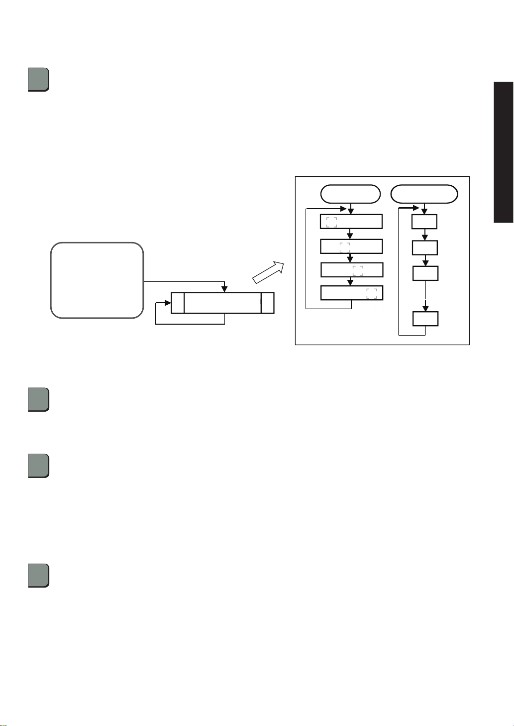
Press the button (Λ) and select the mode you want to change.
*Each time the button (>) is pressed, the display changes from "TCNT" → "PSET" → "NCNT".
1
2
Press the button ( >) to determine the operation mode.
*If you use total count mode or no count mode, proceed to step .
*When using the preset count mode,set the number of presets according to the following procedure.
1) Press the button ( >) to change the blinking digit.
2) Press the button (Λ) to increase the number of the blinking digit.
3) Set it to any setting value.
1
3
Press and hold button (>) (2second)
*The current mode ashes in the count display.
1
1
◇Change operating mode
Follow the steps below to make various settings and changes. (Refer to page 6 for button layout.)
*For details of each operation mode, see P.7.
1
4Press the start button.
*It will start working in the modied mode.
Input digit shift Change the value
0 0 0 0
0 0 0 0
0 0 0 0
0 0 0 0
button (>)
Button(Λ)
0
9
2
1
英語/ENGLISH
11
1
4
Total Count Mode
(TCNT)
Preset Count Mode
(PSET)
No-Count Mode
(NCNT)
MODE CHANGE
Button(Λ)
Button(Λ)
Button(Λ)
Button(>)
Setting the number
of presets
Start button to restart operation
◇How to change the count number
Follow the steps below to change the count number.
1) Press the button ( >) to change the blinking digit.
2) Press the button (Λ) to increase the number of the blinking digit.
3) Change the count number.
*When using the preset count mode, the count cannot be changed beyond the set value.
If you change it, set it to the preset setting value or less.
1
2
Press and hold button (Λ)
*The 4th digit of the count display blinks.
*Changes are limited to use in total count mode or preset count mode.
1
1
1
3Press the start button.
*Operation starts from the changed count quantity.
Used when the count number needs to be changed.
Press and hold the button (Λ)
Change Count
Start button to restart operation
1
1
◇ How to reset the number of counts
Press and hold the reset button (2 seconds). The count number returns to the
initial value.
*When using in total count mode, the count number becomes "0000".
*When using the preset count mode, the count number becomes the set value.
12
英語/ENGLISH
Total Count Mode
(TCNT)
or
Preset Count Mode
(PSET)
Input digit shift change the value
0 0 0 0
0 0 0 0
0 0 0 0
0 0 0 0
Button(>)
Button(Λ)
0
9
2
1

1
2
13
◇ How to open the front panel
1
1Press the lock button (2 places) to release the button. (ref P6)
Remove front panel.
*Be sure that front panel is locked during operation.
*If rivets are clogged, remove unnecessary rivets with the included tweezers.
● CHANGE SIZE OF RIVET
When changing the diameter of the rivet to be used, it is necessary to change the size of the separator
unit and rail unit.Follow the steps below to replace. Be sure to turn o the power before starting work.
*Always check that there are no rivets left inside the feeder before inserting the rivets to be changed.
*If you only change the length of the rivet you are using, you do not need to replace the part.
*The model will be changed by replacing the separator unit and rail unit. Please refer to page 22 for
a list of required parts and models for replacement.
1
1Remove the cover unit.
*Use a hexagonal key wrench
(2.5 mm opposite ats)
*Loosen the 4 locations.
*If the cover unit is dicult to remove,
spread it horizontally.(Bolts will not fall o.)
1
2Remove the separator unit.
*Use a hexagonal key wrench(2.5 mm)
*Loosen the stainless steel screw in the dashed line.
(2 locations)
When you want to check the supply port, or any trouble such as rivet clogging occurs near the supply
port, open the front panel and check. Also, make sure power turned o, to do this.
locked unlocked
英語/ENGLISH
Cover unit
Loosen the hexagon socket
button bolt. (4locations)
Separator unit
Separator unit

14
英語/ENGLISH
◇ Option parts
Separator unit (Type 3) Code No.: 69128
Separator unit (Type 4) Code No.: 69129
Separator unit (Type 5) Code No.: 69130
Rivet rail unit (Type 3) Code No.: 69097
Rivet rail unit (Type 4) Code No.: 69098
Rivet rail unit (Type 5) Code No.: 69099
Clearance gauge Code No.: 70219
Rivet rail unit Separator unit
1
3Remove the rivet rail unit.
*Use a hexagonal key wrench(3 mm)
*Loosen the stainless steel screw in the dashed line. (2 locations)
Enlargement of the circled
part in the left gure
1
4Install the rail unit of the size to be replaced and the separator unit in reverse order.
*The clearance between the separator unit and the rail should be 2 to 2.8mm.
*Improper clearance dimensions can cause rivet jamming.
*If it is dicult to set clearance dimensions, use an optional jig (clearance gauge).
*Insert the clearance gauge into the separator unit as shown in the gure, and attach it so that
it stops naturally with the stopper.
Stopper 2.8mm
Pass 2.0mm
Rivet rail unit
Separator unit
Rivet rail unit
Clearance gauge
Clearance gauge

15
英語/ENGLISH
1
1Remove the frame head holder.
*Use a hexagonal key wrench(3 mm)
*Loosen the stainless steel screw in the dashed line. (3 locations)
◇ Option parts
Frame head holder (21) Code No.: 69154
Frame head holder (23) Code No.: 69168
When changing the riveter to be used, it is necessary to replace the frame head holder. Follow the
steps below to replace. Be sure to turn o the power before performing this work.
*Refer to P8 for replacement, and select the frame head holder that matches the riveter you use.
*The model will be changed by exchanging the frame head holder. Refer to page 22 for a list of
required parts and models for replacement.
1
2Install the frame head holder of the size to be replaced.
*The frame head holder (21) is blue and the frame head holder (23) is black.
Frame head holder
● CHANGE OF THE RIVETER USED

16
英語/ENGLISH
Specify the model name, part name, code No., and quantity as shown below, and place an order with
the store where you purchased the product.
Model Parts name Code No. Qty.
ARF810E Separator unit(Type 3) 69128 1
ARF810E Frame head holder (21) 69154 1
*Note that if the parts are improved, the inventory of the old product will be 5 years.
1.Cleaning each parts.
2.Check parts for damage.
●If there is any damage, contact the store where you purchased
the product.
●Perform maintenance inspections once a week. If neglected, it may
not work properly.
● If there is dirt, wipe it o with a waste cloth.
●Remove dirt and dust from the area around the rivet insertion
port and the supply port by using an air blower, etc.
●If the supply unit does not move smoothly, blow air through the
cleaning hole at the bottom of the supply unit.
* Remove the cover unit before doing this. (See page 13)
Perform the following tasks and checks on a daily basis. Be sure to turn o the power before performing
this work.
●Store the device in a well-ventilated place with little dust and humidity, and in a stable place where
there is no risk of it falling.
●In order to use this machine for a long time, please request regular overhauls from us. (Overhaul
is charged) For overhaul and repair, contact the store where you purchased the product or call us.
3.Storage
Cleaning hole
Supply unit
3.Apply grease.
●If you feel that the riveter insertion is heavy, apply
grease to the locations shown in the gure on the
right.
●Apply grease thinly. If too much, the movement of the
supply unit may be adversely aected.
Slide base L、 R
Push holding
arm stopper
● MAINTENANCE
● ORDERING PARTS

17
英語/ENGLISH
If a problem occurs, check the following.If the problem persists after checking the items in the table be-
low, contact your nearest “LOBSTER” dealer or contact Lobtex.
In making any inquiries about this product or requests for repair work, rst check the troubleshooting
items below and then make a note of the model number, the usage conditions and the trouble symp-
toms in as much detail as possible. If you can provide this kind of information, it may reduce the amount
of time required for delivery or repairs to be completed.
Trouble Cause Countermeasure
The machine will not
operate even though the
start button is pressed.
1The power supply plug or power
supply jack is disconnected.
Connect the power supply plug or
power supply jack.
2The lid is open and the safety
switch is working Close the lid tightly
Rivets will not feed to the
riveter. 1Rivet jammed in the rail Open the lid and remove the jammed
rivet
2Size of Nosepiece is not
appropriate for blind rivets.
Change the size of nosepiece to that
appropriate for blind rivets.
3The vacuum mechanism of the
riveter is not turned on.
Turn on the vacuum mechanism.
4Volume of blind rivets loaded
exceeds appropriate level.
Reduce the volume of loaded rivets
to the appropriate level.
5Items other than rivets are inserted Insert rivets only
6Rivet clogging in the supply section Open the front panel and remove the
clogged rivet (see page 13).
7The rails of the rivet rail unit are
dirty.
Clean the rails and remove any dirt.
8The riveter is not correctly inserted
into the inner side of the frame
head holder.
Plug it in until the green LED ashes
and the buzzer sounds
9Separator clogged with rivets Open the lid and remove the jammed
rivet.
10 Poor movement of supply unit Use the cleaning hole to blow air.
(See page 16)
● TROUBLESHOOTING
18
英語/ENGLISH
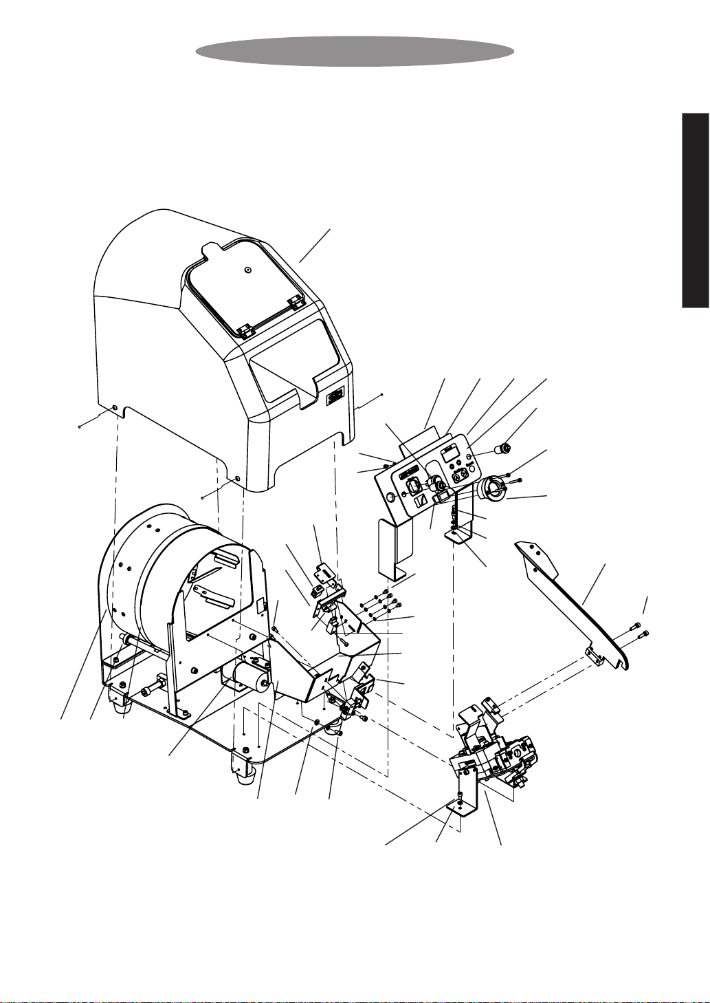
● PARTS TABLE
ARF-810E main unit
2
4
7
11
5
8
10
9
6
3
13
12
15
14
17
18
19
16
20
21
29
22
23
24 25
1
28
27
32
30
31
26
6
6
5
28
18
17

19
英語/ENGLISH
Index No. Part name Code No. Material
1Drum unit Stainless
2Supply port unit 69083 Steel
3-A Rivet rail unit (Type 3) 69097 Steel、Stainless
3-B Rivet rail unit (Type 4) 69098 Steel、Stainless
3-C Rivet rail unit (Type 5) 69099 Steel、Stainless
4-A Separator unit (Type 3) 69128 Steel、Stainless
4-B Separator unit (Type 4) 69129 Steel、Stainless
4-C Separator unit (Type 5) 69130 Steel、Stainless
5Spring washer M4 20930 Steel
6Hex socket bolt M4×8 20918 Steel
7Electric feeder substrate unit 69167 Electronic device
8Sensor plate 70218 Stainless
9Hex socket head bolt with spring washer M 4×15 69157 Stainless
10 Alignment check sensor 69161 Electronic device
11 Hex socket head bolt with spring washer M 3×8 61443 Stainless
12 Power switch 69164 Electronic device
13 Start button 69163 Electronic device
14 Safety switch mounting plate 69174 Steel
15 Safety switch 69165 Electronic device
16 Hex socket bolt M 3×12 61337 Steel
17 Spring washer M3 12442 Steel
18 Hex socket bolt M3×5 43736 Steel
19 Camlock fastener 69162 Plastic
20 Front basket 69136 Stainless
21 Substrate mounting plate 69138 Steel
22-A Frame head holder φ21 69154 Plastic
22-B Frame head holder φ23 69168 Plastic
23 Cover unit 69715 Plastic、
Stainless、Steel
24 Front panel 69159 Stainless
25 Panel sheet 69169 Plastic
26 Safety swich xing plate 70336 Steel
27 Hex socket bolt M 3×25 67673 Steel
28 Plain washer M4 25585 Steel
29 Plain washer M3 21539 Steel
30 Motor 69105 Electronic device
31 Bearing 69120 Steel
32 Belt 69111 Rubber
Parts with circled Index No. are consumable parts.
They should be replaced periodically.
Other manuals for ARF-810E
1
Table of contents


