Locatechs LocaSafe VA10 Base Station User manual
LocaSafe VA10 Base Station
INSTALLATION AND OPERATING MANUAL
V1.1
1. Introduction
LocaSafe VA10 Base Station is a part of the LocaSafe safety system: an innovative proximity warning
system that is designed to improve the workplace safety by reducing the risk of vehicle-personnel
collisions.
The Base Station is multi-functional. This manual describes the case where the Base Station is installed
on a vehicle, e.g. a forklift.
2. System Description
2.1. Product Summary
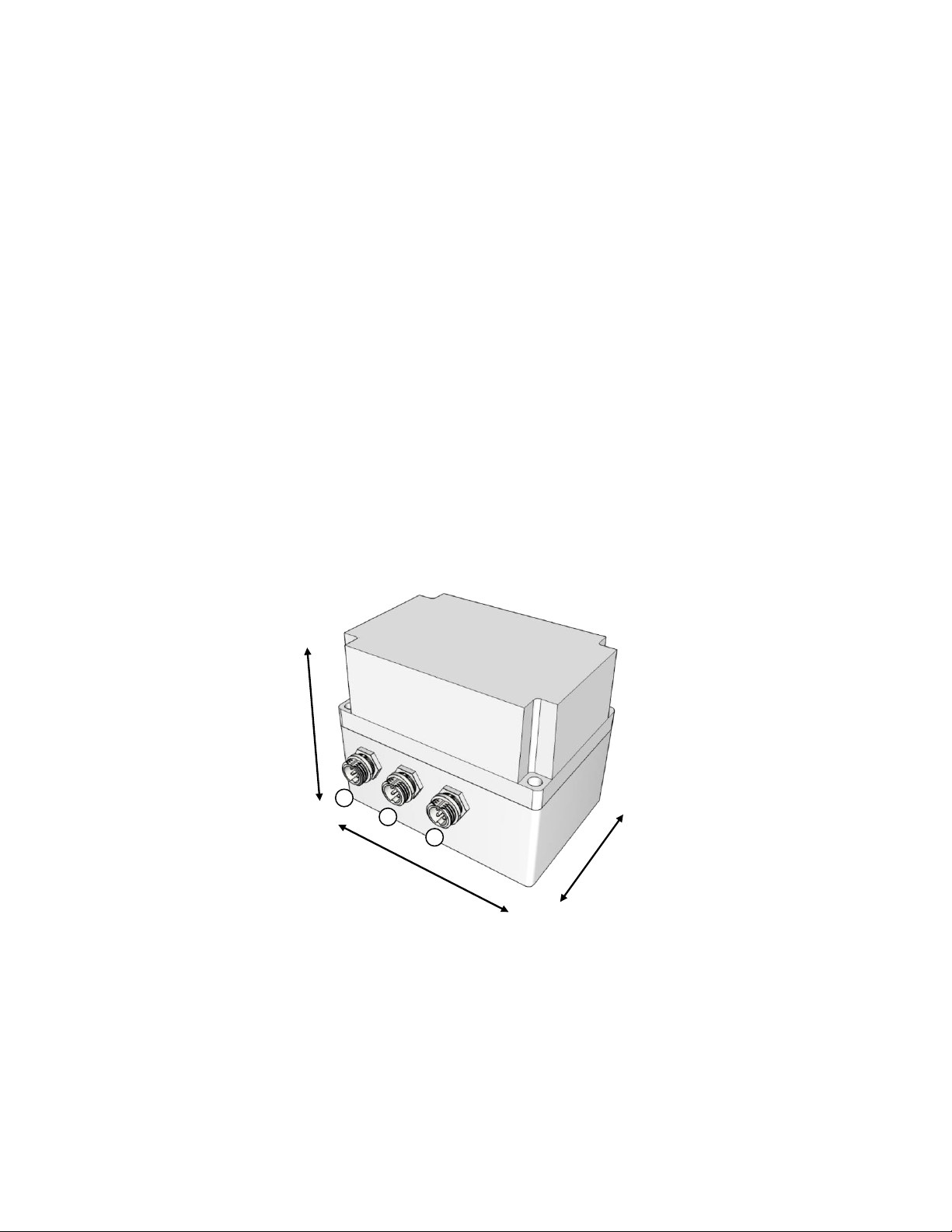
Figure 1 Exterior Drawing
C1 Power supply / VDR connector
C2 Relay Controller 1
C3 Relay Controller 2
Length: 110 mm
Width: 75 mm
Height: 90 mm
c1
c2
c3

2.2. Working principle
The Base Station uses the Ultra-Wideband (UWB) radio wave to measure the distance between itself
and safety Tags (equipped by personnel), with an accuracy of ±20cm. When the distance is reduced to a
pre-set safe limit, the Base Station will warn the driver to avoid the possible collision.
2.3. Features
•Long range and 360°collision risk detection
•Perfect for blind intersections –Line-of-Sight not required
•Fully configurable to meet application requirements
•Easy to install and maintain
2.4. System Specification
Standard
802.15.4a
Frequency
6.5 GHz
Usable Detection Range
40 meters, 360 degree
Tracking Accuracy
±20 cm
Tracking Capacity
20 Tags per second
Outputs
2x Relay-contracts, normally open, max. load 24 VDC 1A
Antenna
Internal antenna
Bluetooth Interface
Internal antenna, typical range 10 meters
Power Supply
6 –24 VDC
Housing
PVC
IP Rating
IP65
Operation Temperature
-20°C to 70°C
Humidity
5 –95% (no condense)
Dimensions
75x110x90 mm
2.5. Packing List
LocaSafe VA10 Base Station x1
12V 2-colors LED alarm bar with 2 meters cable x1
2 meters Power supply cable x1
Mounting set x1
3. System Installation
3.1. Base Station
The Base Station should be installed on top of a vehicle, preferably on the middle line. Figure 2 shows
the approximate mounting position of the Base Station on a forklift.
3.2. LED Alarm Bar
Two 12V LED Alarm Bars are included in the package. Their mounting positions on a vehicle should be
appropriately chosen so that the driver is able to notice the warning light but will not be blind by it.
Figure 2 shows an example installation position.
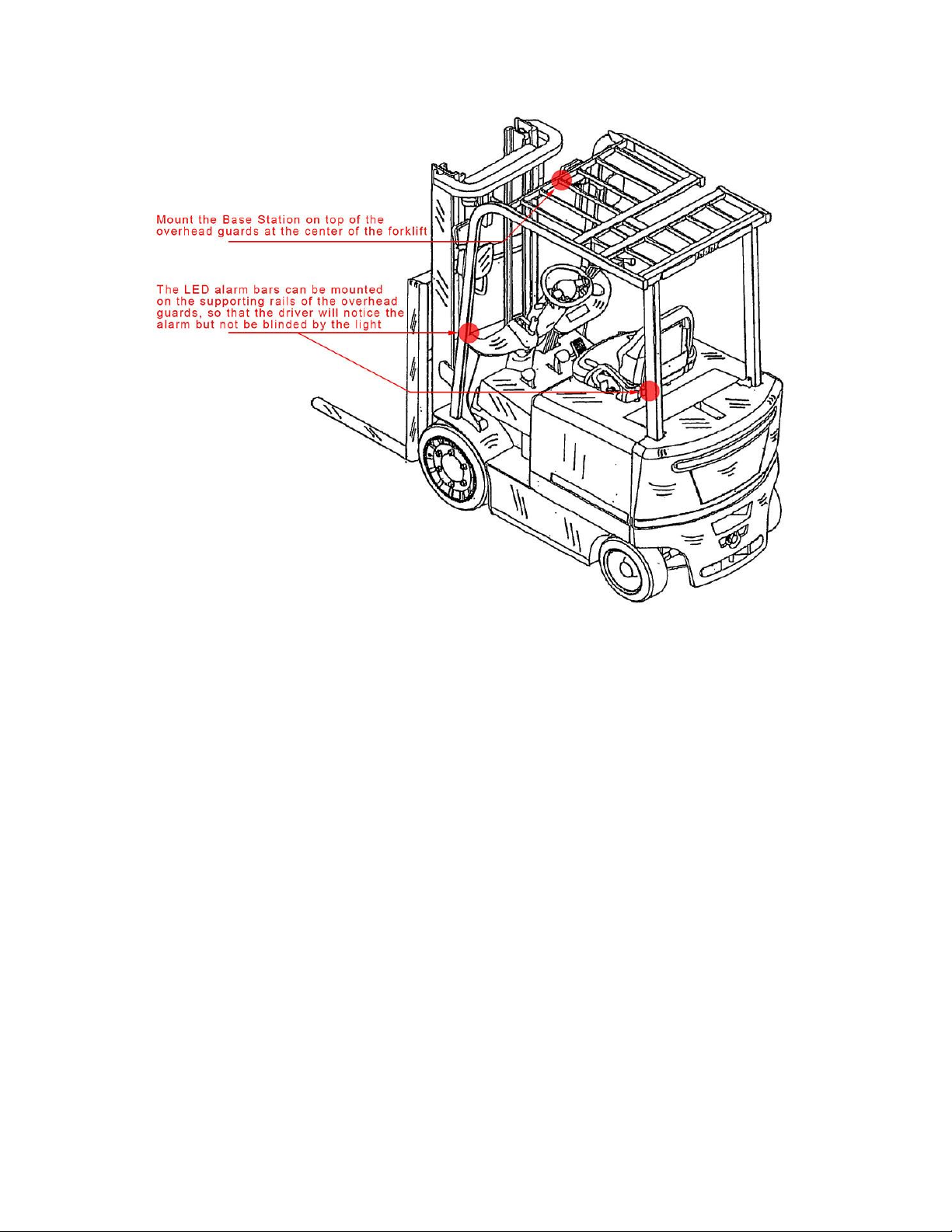
Figure 2 Recommended Mounting Positions for the Base Station and LED alarm bars
3.3. Electrical Connections
3.3.1. Relay
The Base Station contains two relays to actuate alarm devices (e.g. LED bar). The relays are normal open
and have contact rating of 10A 28VDC.
3.3.2. Power Supply
Both the Base Station and the externally connected alarm device (connected with the relays) are
powered by the same direct current (DC) source. The Base Station has an internal voltage regulator
which accepts input power range between 6V and 24V. But the allow input voltage is limited by the
input voltage of the alarm device. For example, the voltage rating of the LED alarm bar is 12V, then the
allowed input voltage of the Base Station is limited to 12V.
3.3.3. Cable Connections
The Base Station has one power cable connector and two relay connectors. The power cable included in
the package can be used to connect the Base Station to the power supply. The two relay cables are used
to connect the Based Station with the LED alarm bars. If a different alarm device is going to be used
instead of the LED bar, the cable header at the LED bar side needs to be replaced. The cable connections
are illustrated in Figure 3.
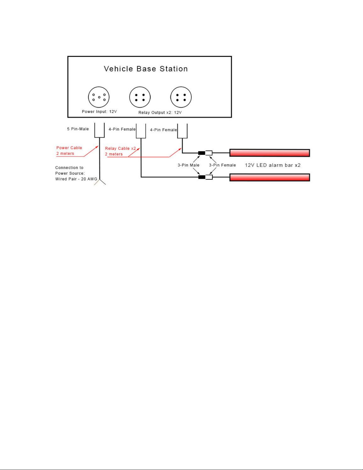
Figure 3 Base Station Connections
3.4. Set Alarm Distance
By default, the Base Station works with two alarm levels: warning and critical. The trigger distance for
each of the levels is pre-set by Locatechs based on tests that will be conducted at the customer site.
4. Usage
4.1. Power On
The Base Station has no power switch. It is powered on when its power source is activated. When
powered on, the Base Station will first execute its self-diagnostic process which may produce two signals
by default (equipped with the LED bars):
1. All OK: the LED bar flashes “Red-Blue” pattern once
2. Error: the LED bar flashes “Red-Blue” pattern for 3 times
4.2. Trigger and Clear Alarm
Alarm is triggered based on the distance between the Base Station and the Safety Tag. Figure 4 to Figure
6 illustrate the different situation of alarm
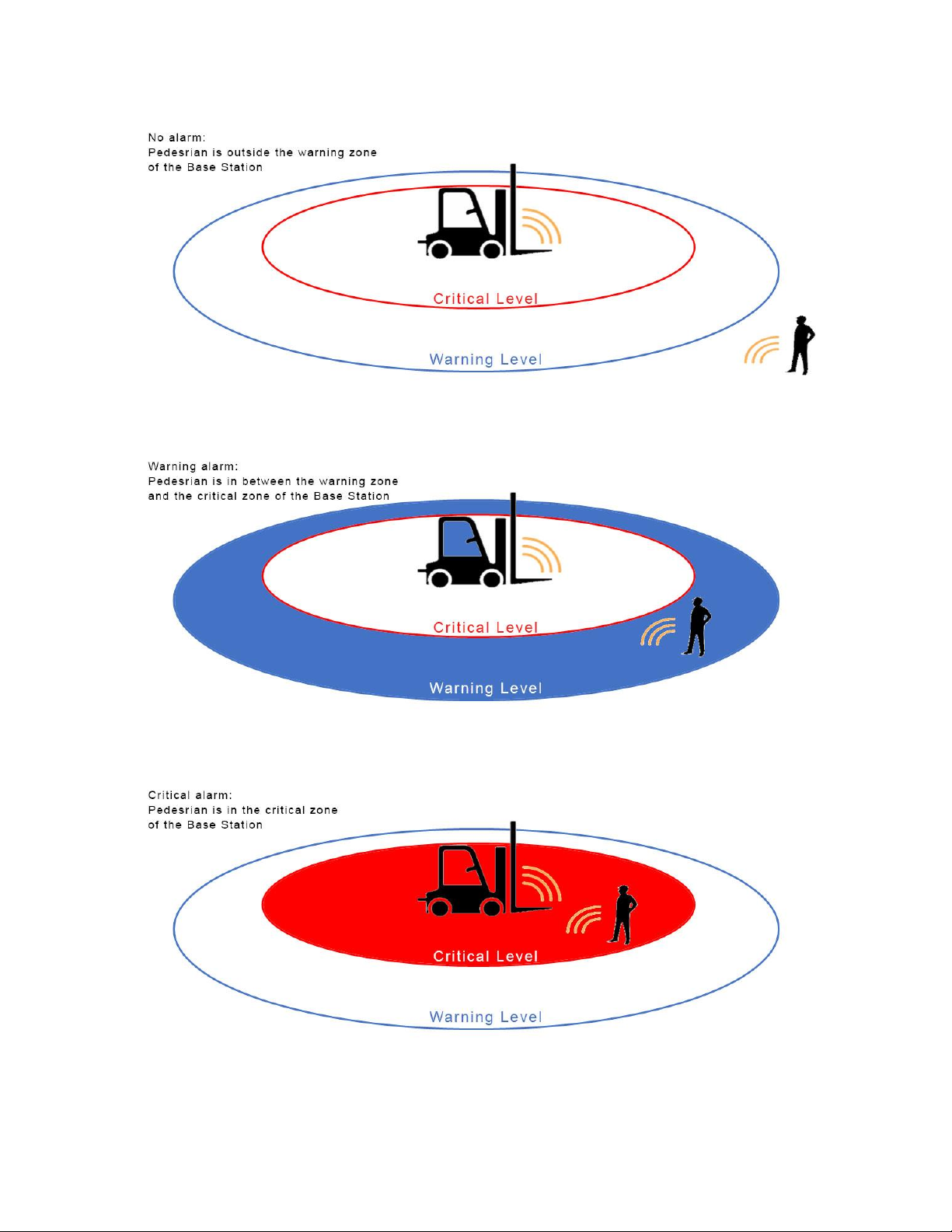
Figure 4 No Alarm
Figure 5 Warning Alarm
Figure 6 Critical Alarm

When multiple pedestrians are presented in different alarm zones, the alarm is triggered by the
pedestrian who is the closest to the Base Station. This situation is demonstrated by Figure 7.
Figure 7 Critical Alarm triggered by the closest pedestrian
5. Configuration
Configuration of the base station go through USB configurator. You need a computer with USB
connector and can run either windows, Linux or OS X.
The following settings on base station can be changes:
•Anchor_id: Id of the anchor in base station. Normally shouldn’t be changed.
•Notify Distance: Notify /Blue light zone radius, in centimeter
•Alarm Distance: Alarm /Red light zone radius, in centimeter
•Driver Zone: Inactive zone. (Disabled by default, can be opened on demand)
•Tag Vibration Mode: 0 for not sending vibrate signal, other value for vibrate
•Tag Vibration Distance: Vibration radius, in centimeter
•Intersection Distance: (Disabled by default, can be opened on demand) Intersection radius for
trigger intersection event, in centimeter
5.1 Software Install
The configurator uses FT232R chip from FTDI.
There is a good chance your operation system will install the driver automatically. If not, please check
the page below and install the correct driver for your OS.
https://www.ftdichip.com/Drivers/D2XX.htm
With the driver installed, you can use any UART terminal to communicate with the base station.
For example:
•Termite for windows https://www.compuphase.com/software_termite.htm
•CoolTerm for windows, linux and OS X https://freeware.the-meiers.org/
To communicate with Base station, you need to choose Baud rate of 115200 and the port which belongs
to the USB configurator.
For example,
•“SLAB_USBtoUART” in OSX
•“COM7” in windows. You can find the correct port in device manager
5.2 Config Base Station
When everything is connected, you can start with configuration. We use Termite for example.
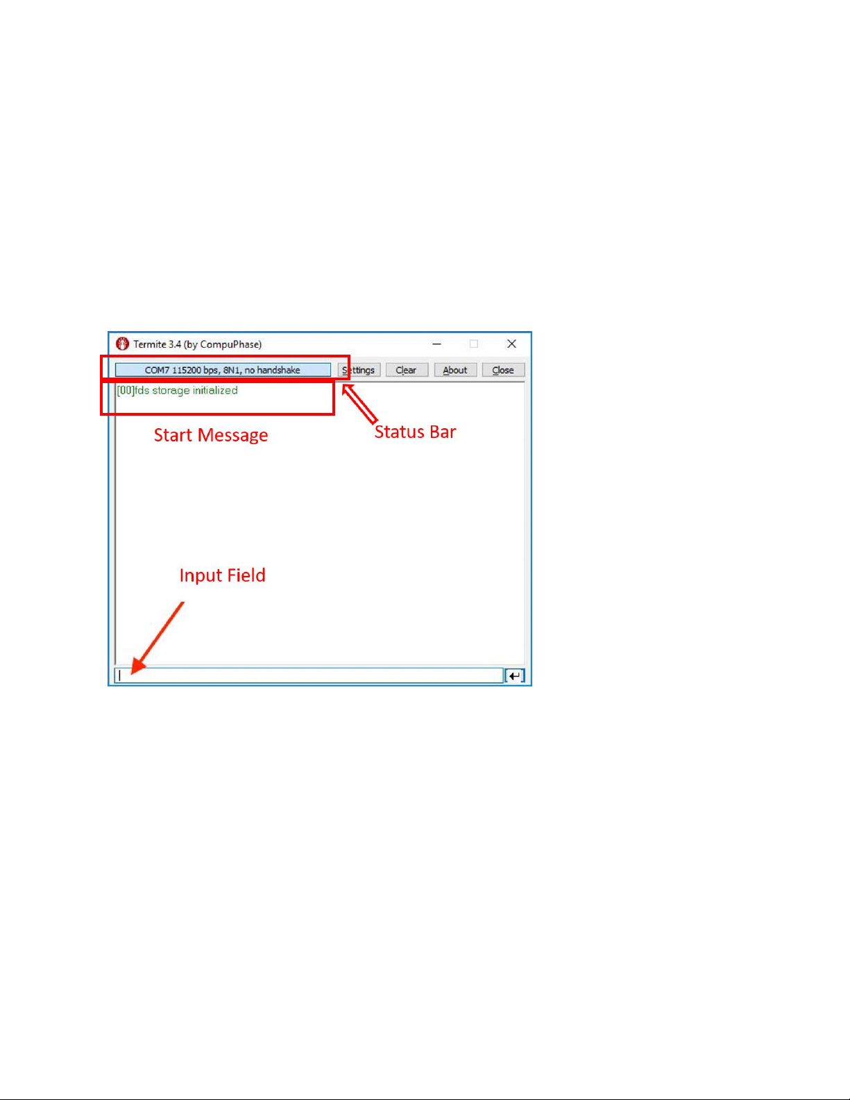
5.2.1 Interface Overview
•Status Bar: contains connection information, “COM7” for port, “115200 bps” for speed
•Start Message: “fds storage initialized” indicates system started
•Input Field: for all user inputs, press “enter” key, or the enter button on the right to confirm
inputs
•Possible Actions:
oClick on input field and press enter to go to Config Page
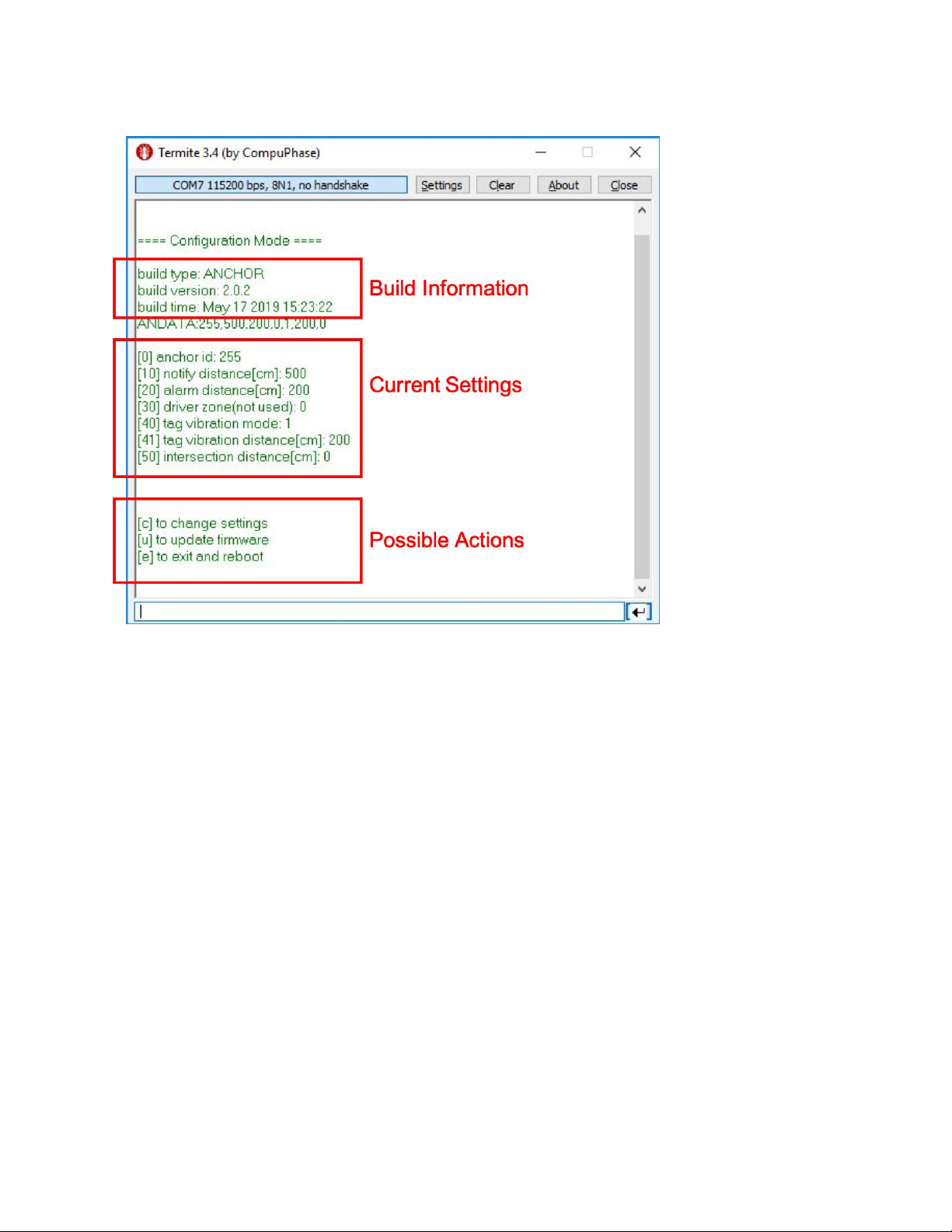
5.2.2 Main Config Page
•Build Information: general information for current firmware
•Current Settings: Current setting in base station
•Possible Actions:
oType “c” in input field and press enter to go to Setting Page
oType “u” to enter Bluetooth firmware update mode
oType “e” to exit setting page and reboot the base station
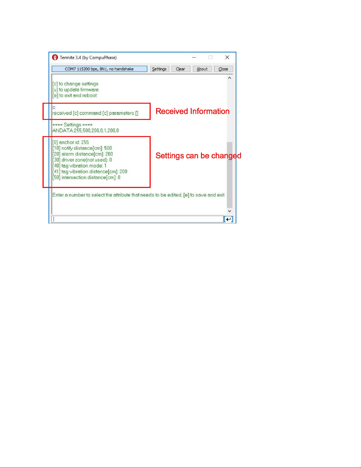
5.2.3 Setting Page
•System go to Setting Page when user enters “c” in Main Config Page.
•All Settings will be displayed again here.
•Possible Actions:
oEnter the index of the setting, will go to setting change page
oEnter “e” to save current settings and go back to main page
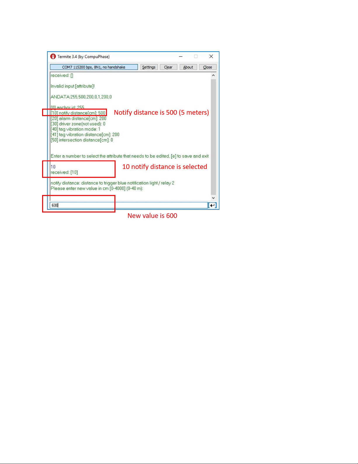
5.2.4 Change a Setting
•Enter 10 go to notify distance change page
•Enter 600 as new notify distance value
•Possible Actions:
oCan only enter a new value here
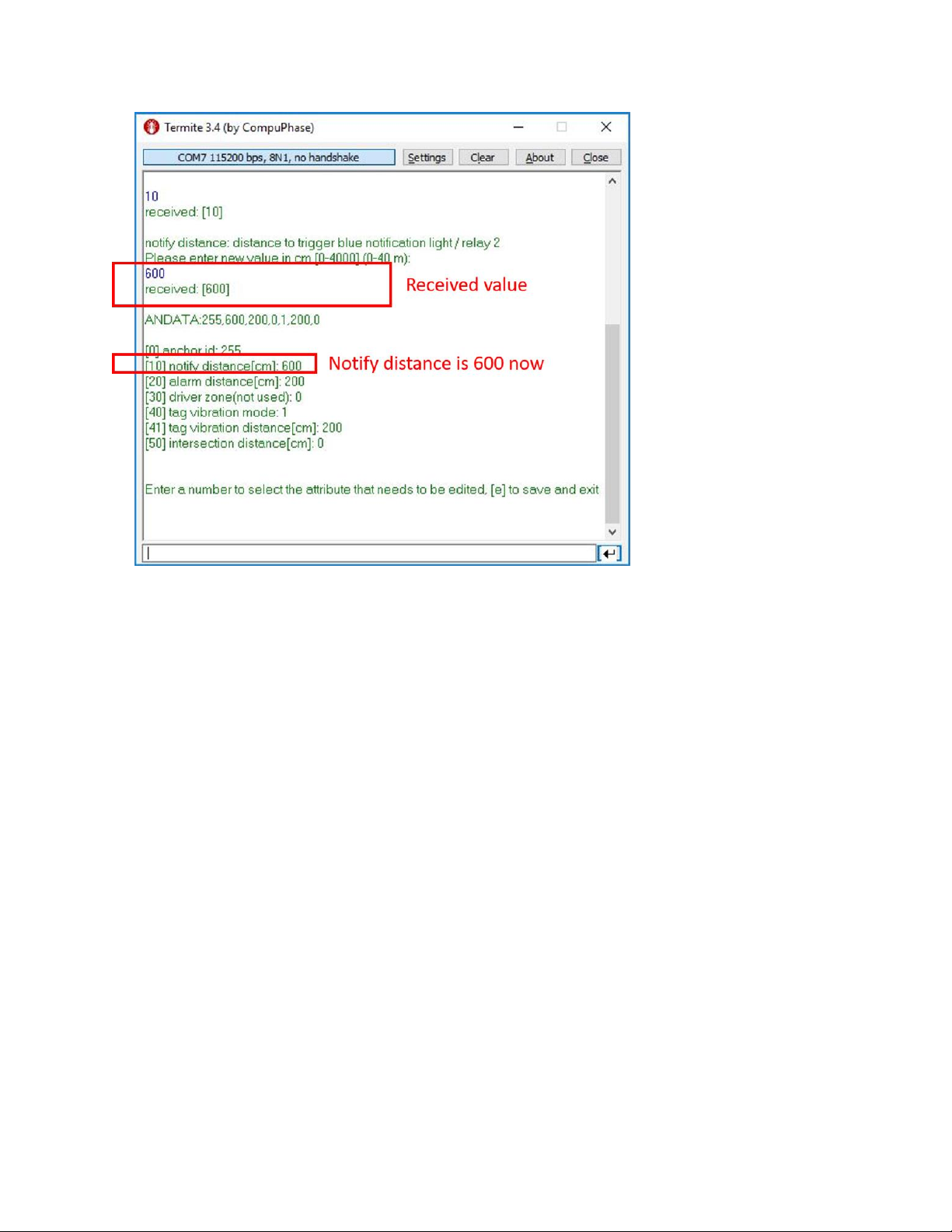
•Received value: “received [x]” x Indicates what base station actually got from user
•Can confirm the new distance “600” in settings section
•Possible Actions:
oEnter the index of the setting, will go to setting change page
oEnter “e” to save current settings and go back to main page
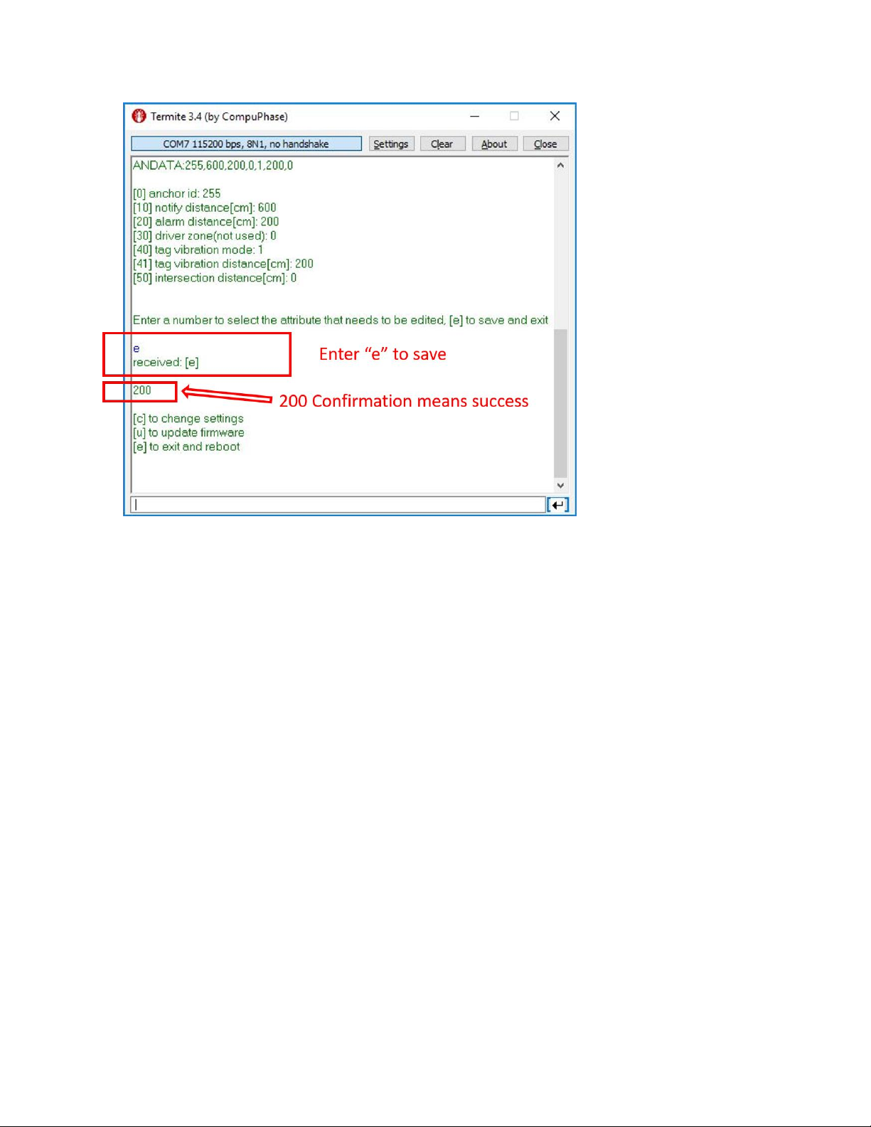
•Enter “e” to save the setting, settings are saved to storage from this step
•Save can be confirmed with 200 return code
•Possible Actions:
oType “c” in input field and press enter to go to Setting Page
oType “u” to enter Bluetooth firmware update mode
oType “e” to exit setting page and reboot the base station
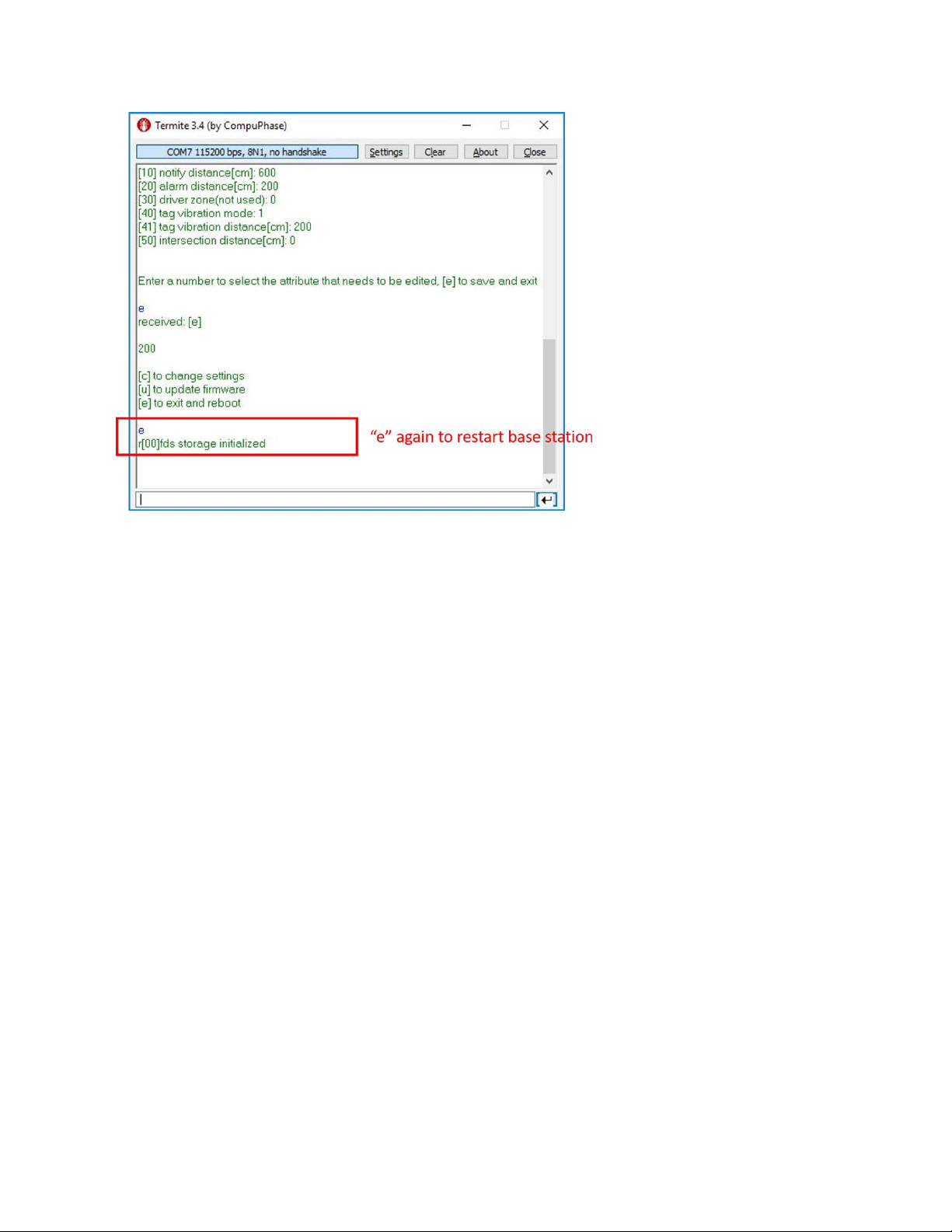
•Enter “e” to manually restart base station

6. Statement
The LocaSafe system (the Product) constitutes a safety aid instrument to prevent man-vehicle collisions
in working areas. It does not constitute a personal safety system as it does not interact in any way with
the machines on which it is installed (for example, applying the brakes etc.)
Inherently, the LocaSafe system's effectiveness is subordinate to the operator's action whenever and
wherever, and in any case, it does not exonerate the Buyer and the operator from adopting routine
safety procedures required for any specific operating situation (organizing the construction site, training
operators on safety, designing signs, necessary cautions etc.) and from observing due diligence
regulations.
Furthermore, the LocaSafe system, cannot guarantee the connection to radio frequency and therefore
detection taking place in any case, given that this connection cannot occur properly because of
electromagnetic interferences or due to other causes such as the lack of power of one or more devices,
for example.
Locatechs B.V will not be held liable in any way for any direct or indirect damages, of any kind (including
personal injury or property damage) subject to any matter whatsoever experienced by the Buyer or
third parties as a result of using the Product.
Table of contents
Popular Security Sensor manuals by other brands

Duramaxx
Duramaxx Powerpoint manual

Inficon
Inficon IRwin quick start guide

Lightning Protection International
Lightning Protection International GUARDIAN PLUS installation manual

Risco
Risco Wireless VITRON RWT6G installation instructions

Lamtec
Lamtec F 200 K Technical documentation

mPower Electronics
mPower Electronics VOXI user guide


