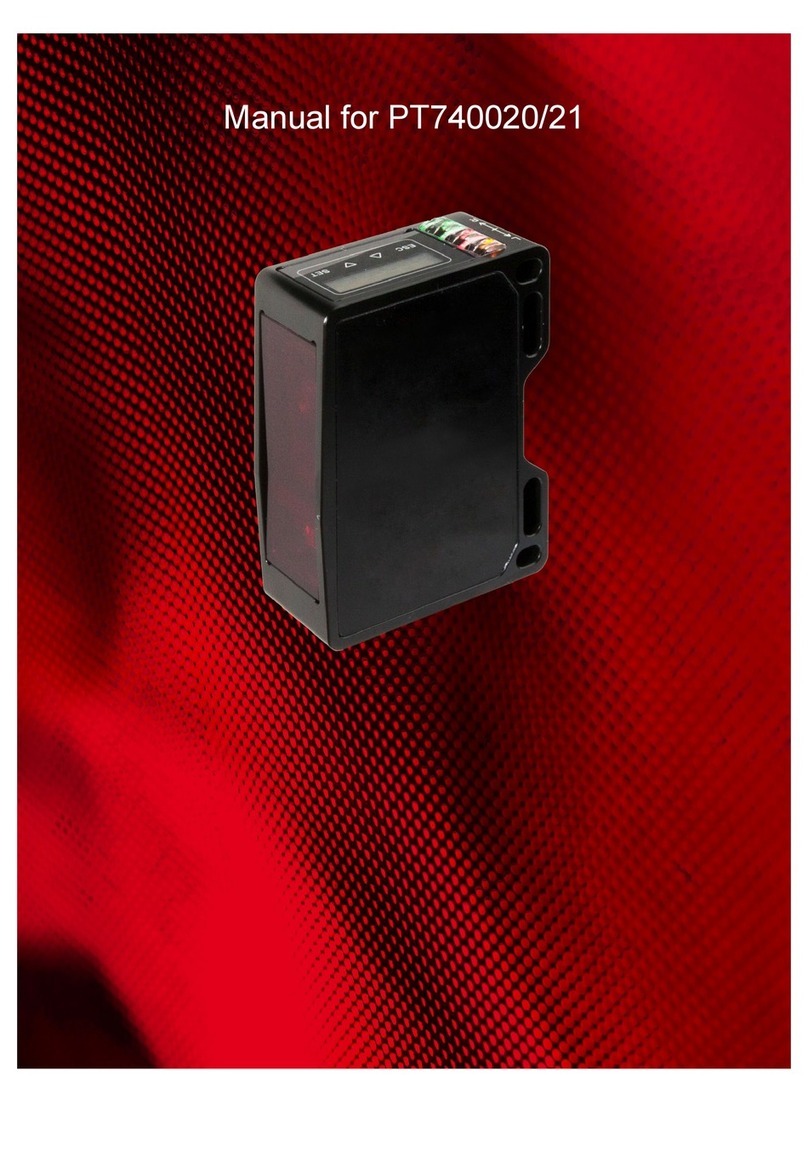
ipf electronic PY740025 User manual

Manual for PY740025/26

MANUAL [PY740025/26]•Subject to alteration! Version: 22.10.2018
ipf electronic gmbh
• Kalver Straße 25 - 27 • 58515 Lüdenscheid
│
Tel +49 2351 9365-0 • Fax +49 2351 9365-19
│
info@ipf.de • www.ipf.de 2
Contents
1General information......................................................................................................................3
1.1 Concerning the contents of this document .....................................................................................3
1.2 Intended use ...................................................................................................................................3
1.3 Safety warnings ..............................................................................................................................3
2Commissioning.............................................................................................................................4
3Connection ....................................................................................................................................8
3.1 Connection cable ............................................................................................................................8
3.2 Pin assignment and connection diagram........................................................................................9
4Installation ...................................................................................................................................10
4.1 Mounting .......................................................................................................................................10
4.2 Sensor reference levels ................................................................................................................10
4.3 The reference surface................................................................................................................... 11
4.4Measuring field defintion...............................................................................................................12
4.5 Mounting .......................................................................................................................................14
4.6 Installation accessories.................................................................................................................16
5Configuration ..............................................................................................................................17
5.1 Overview of control elements .......................................................................................................17
5.2 Function tree .................................................................................................................................20
5.3 LIVE MONITOR ............................................................................................................................21
5.4 MESSTYP.....................................................................................................................................24
5.5 FLEX MOUNT (Function HEIGHT)...............................................................................................25
5.6 OBJECT........................................................................................................................................30
5.7 PRECISION ..................................................................................................................................30
5.8 FIELD OF VIEW ...........................................................................................................................33
5.9 ANALOG OUT ..............................................................................................................................35
5.10 DIGITAL OUT................................................................................................................................37
5.11 SYSTEM .......................................................................................................................................39
5.12 SETTING ......................................................................................................................................41
6Function and definition ..............................................................................................................42
6.1 Sensors data sheet.......................................................................................................................42
6.2 Functional principle.......................................................................................................................47
6.3 Measuring repetition time and response time...............................................................................49
6.4 Hysteresis .....................................................................................................................................50
6.5 Object to be measured .................................................................................................................52
6.6Interfaces and outputs ..................................................................................................................53
6.6 Touch panel...................................................................................................................................61
6.7 Memory .........................................................................................................................................61
6.8 Standard deviation........................................................................................................................62
7Safety instructions and maintenance.......................................................................................63
7.1 General safety instructions ...........................................................................................................63
7.2 Part identification ..........................................................................................................................63
7.3 Influence of ambient light..............................................................................................................65
7.4 Front (optics).................................................................................................................................65
7.5 Cleaning the sensors ....................................................................................................................65
7.6 Disposal ........................................................................................................................................65
8Error correction and tips............................................................................................................66
8.1 Examples of sensor setup ............................................................................................................66
8.2 Error correction .............................................................................................................................67

MANUAL [PY740025/26]•Subject to alteration! Version: 22.10.2018
ipf electronic gmbh
• Kalver Straße 25 - 27 • 58515 Lüdenscheid
│
Tel +49 2351 9365-0 • Fax +49 2351 9365-19
│
info@ipf.de • www.ipf.de 3
1 General information
1.1 Concerning the contents of this document
This manual contains information about the installation and initial setup of the ipf PY740025 and PY740026
light section sensors.
It is a supplement to the mounting instructions supplied with each sensor.
1.2 Intended use
The PY740025/26 sensors measure heights of objects. It was especially developed for easy handling, flexible
use, and precise measurement.
1.3 Safety warnings
NOTE
Provides helpful operation instructions or other general recommendations.
ATTENTION!
Indicates a possibly hazardous situation. If it is not avoided, minor or slight injuries
can occur or the device can be damaged.
Read these operating instructions carefully and follow the safety instructions!

MANUAL [PY740025/26]•Subject to alteration! Version: 22.10.2018
ipf electronic gmbh
• Kalver Straße 25 - 27 • 58515 Lüdenscheid
│
Tel +49 2351 9365-0 • Fax +49 2351 9365-19
│
info@ipf.de • www.ipf.de 4
2 Commissioning
After the sensor is connected and installed, configure it via the display. The sensor is then ready for operation
and outputs the measuring value in mm to the screen. Optionally, the measuring field can be limited or the
switching output can be configured.
Connection
Installation
Application specific settings
(Optional settings)
Let's get started
Connection
Connect the sensor according to the connection
diagram. A shielded connection cable (8-pole M12)
must be used.
When everything is correctly connected, the sensor
starts up.
Legend function: 1 = n. c., 2 = L+, 3 = 4-20mA/0-10V, 4 = Push
Pull, 5 = Alarm Push Pull, 6 = n. c., 7 = L-, 8 = Hold
Legend colors: 1 = WH (white), 2 = BN (bronn), 3 = GN (green), 4
= YE (yellow), 5 = GY (gray), 6 = PK (pink), 7 = BU (blue), 8 = RD
(red)
Key functions
ESC = Back
ESC 2 sec. = Run mode
UP = Up/increase value
DOWN = Down/decrease value
SET = OK
SET 2 sec. = Save value
Slide over all 4 keys:
----> = Enables the panel if locked
<---- = Jump to run mode
Setting the language
The language is selected and confirmed by pressing
SET for 2 seconds.
English
Deutsch
Italiano
Français
1
LANGUAGE
English
1
2
3
4

MANUAL [PY740025/26]•Subject to alteration! Version: 22.10.2018
ipf electronic gmbh
• Kalver Straße 25 - 27 • 58515 Lüdenscheid
│
Tel +49 2351 9365-0 • Fax +49 2351 9365-19
│
info@ipf.de • www.ipf.de 5
Installation
Function HEIGHT
At the function HEIGHT, the reference surface will be
teached-in with FLEX MOUNT.
The sensor can be mounted angled with up to +/- 30°
to the reference surface.
The sensor may be mounted at an angle inclined
maximally 30° to the left or to the right of the
reference surface (background). Reference surface
(background) and object must lie within the
measuring field.
2
0 mm
Measuring
field width right
Measuring
field width left
Right
Left
0 mm
FIELD OF
VIEW
+/-30°
Reference surface
Reference point
HEIGHT function
Blind region

MANUAL [PY740025/26]•Subject to alteration! Version: 22.10.2018
ipf electronic gmbh
• Kalver Straße 25 - 27 • 58515 Lüdenscheid
│
Tel +49 2351 9365-0 • Fax +49 2351 9365-19
│
info@ipf.de • www.ipf.de 6
Application specific settings
1In the factory settings Delta HEIGHT is predefined
HEIGHT
Height of an object
For a height measurement, the required MEAS TYPE
(average value, maximum, minimum or delta). The
reference surface (0) is the maximum measuring range
of the sensor, or if present, the FLEX MOUNT teached
reference surface.
Avg HEIGHT = Distance of the average
value of the object from the
reference surface
Max HEIGHT = Distance of the furthest
measuring point from the
reference surface
Min HEIGHT = distance of the closest
measuring point from the
reference surface
Delta HEIGHT1= Difference between the
closest and furthest measuring
point
Avg HEIGHT Max HEIGHT
Min HEIGHT Delta HEIGHT
3

MANUAL [PY740025/26]•Subject to alteration! Version: 22.10.2018
ipf electronic gmbh
• Kalver Straße 25 - 27 • 58515 Lüdenscheid
│
Tel +49 2351 9365-0 • Fax +49 2351 9365-19
│
info@ipf.de • www.ipf.de 7
Optional settings
FLEX MOUNT
If the sensor is mounted at an angle or the reference surface is not at the End of the measuring range Sde,
FLEX MOUNT must be activated and the reference surface taught in.
If FLEX MOUNT is activated, the following settings are reset: SCALE OUT, FIELD OF VIEW and DIGITAL
OUT.
OBJECT
Selection of bright or dark objects to optimize the measurement results.
PRECISION
To achieve better precision and resolution, it is possible to alternate between Standard, High and Very High
by filtering the output values.
SCALE OUT
Start of measuring range Sdc and end of measuring range Sde can be changed with SCALE OUT. 0V or 4mA
then apply for the start of measuring range Sdc. 10V or 20 mA apply for the point at the end of measuring
range Sde.
FIELD OF VIEW
The width of the measuring field can be changed with FIELD OF VIEW. Separate configuration of the single
points of the field: LIMIT LEFT, LIMIT RIGHT.
This function is required when there are objects in the measuring field that should not be detected.
ANALOG OUT
Start of measuring range Sdc (Offset) and end of measuring range Sde (Height) can be changed with SCALE
OUT. 0V or 4mA then apply for the start of measuring range Sdc. 10V or 20 mA apply for the point at the end
of measuring range Sde. Voltage and current output is selected under ANALOG OUT. In addition, the output
curve can be inverted under OUTP. SLOPE.
DIGITAL OUT
The sensor is equipped with a switching output that can be configured as a threshold or as a window via the
DIGITAL OUTPUT function.
Threshold: As soon as the measuring value is greater than the entered threshold, the switching output will be
changed.
Window: As soon as the measuring value is outside the entered window, the switching output will be changed.
Let's get started
The sensor continuously outputs the measuring value in mm to the display and transmits it via the analog
output to the control.
4
3b

MANUAL [PY740025/26]•Subject to alteration! Version: 22.10.2018
ipf electronic gmbh
• Kalver Straße 25 - 27 • 58515 Lüdenscheid
│
Tel +49 2351 9365-0 • Fax +49 2351 9365-19
│
info@ipf.de • www.ipf.de 8
3 Connection
3.1 Connection cable
An 8-pole, shielded connection cable (cable socket) is required.
We recommend the ipf connection cables with the following article numbers:
•VK205A21/25 (Length 2m, M12 socket angular/straight)
•VK505A21/25 (Length 5m, M12 socket angular/straight)
•VKA05A21/25 (Length 10m, M12 socket angular/straight)
Other cable lengths are available.
When the analog output is used, the cable length affects signal noise. Signal noise increases the longer the
connection cable is.
Analog output I_OUT
Noise: 5.92 uA (1 Sigma) (10 m cable and 680 ohm)
3:59 uA (1 sigma) (2m cable and 680 ohm)
Analog output U_OUT
Noise: 4.80 mV (1 Sigma) (10m cable and 100 kOhm)
3:03 mV (1 Sigma) (2m cable and 100 kOhm)
ATTENTION!
Laser class 1 laser beam according to EN 60825-1:2007. This product can be
operated safely without any additional safety precautions. Nevertheless direct
contact between the eye and beam should be avoided.
ATTENTION!
The IP protection class is valid only if all connections are connected as
described in the technical documentation.
ATTENTION!
Connection, installation and commissioning may only be performed by qualified
personnel.
ATTENTION!
Incorrect supply voltage will destroy the device!

MANUAL [PY740025/26]•Subject to alteration! Version: 22.10.2018
ipf electronic gmbh
• Kalver Straße 25 - 27 • 58515 Lüdenscheid
│
Tel +49 2351 9365-0 • Fax +49 2351 9365-19
│
info@ipf.de • www.ipf.de 9
3.2 Pin assignment and connection diagram
Color
Function
Description
Pin 1
WH = white
n.c.
Not connected
Pin 2
BN = brown
+ Vs
Voltage supply (+15…+28 VDC)
Pin 3
GN = green
analog
Analog output (4…20 mA or 0…10V)
Pin 4
YE = yellow
out
Switching output, push-pull
Pin 5
GY = gray
alarm
Alarm output, push-pull
Pin 6
PK = pink
n.c.
Not connected
Pin 7
BU = blue
0V
Grounded GND
Pin 8
RD = red
Sync in
Input synchronization
NOTE
It is recommended to connect unused inputs to GND (0V).

MANUAL [PY740025/26]•Subject to alteration! Version: 22.10.2018
ipf electronic gmbh
• Kalver Straße 25 - 27 • 58515 Lüdenscheid
│
Tel +49 2351 9365-0 • Fax +49 2351 9365-19
│
info@ipf.de • www.ipf.de 10
4 Installation
4.1 Mounting
The sensor has four mounting holes for flexible alignment and mounting. The use of 2 M4x35 screws is
recommended for mounting. The tightening torque is max. 1.2 Nm.
4.2 Sensor reference levels
To ensure easy alignment of the sensor during installation, the surfaces defined here are available:
The laser beam of the sensor runs parallel ( // ) to level R3 and is at a right angle to levels R1 and R2. Levels
R1, R2, and R3 serve as references for sensor alignment during installation. "Left" and "Right" designations
are also important.
Tightening torque
max. = 1.2 Nm
19 mm
Level R3
Laser-
beam
Level R1
Level R2
13 mm
ATTENTION!
Connection, installation and commissioning may only be performed by qualified
personnel. Protect optical surfaces from moisture and dirt.
Left
Right

MANUAL [PY740025/26]•Subject to alteration! Version: 22.10.2018
ipf electronic gmbh
• Kalver Straße 25 - 27 • 58515 Lüdenscheid
│
Tel +49 2351 9365-0 • Fax +49 2351 9365-19
│
info@ipf.de • www.ipf.de 11
4.3 The reference surface
If the height of the object is to be measured from a specific surface or the sensor is mounted at an angle up to
±30°, then the reference surface must be taught in with the FLEX MOUNT function.
The following points must be satisfied for teaching in the reference surface:
•The reference surface must lie within the measuring range of the sensor.
•The sensor may be inclined at a maximum angle of ±30° to the reference surface.
•The "Maximum reference surface unevenness"1must not exceed the maximum value.
•The length of the reference surface must not be less than the "minimum reference surface length"1
value.
1According to data sheet chapter 6.1
NOTE
The reference surface…
•should be as flat as possible
•should cover the entire measuring range (width) if possible
•can be teached-in with the FLEX MOUNT function
Reference surface
Object
Min. reference
surface length
Angle:
(0° shown)

MANUAL [PY740025/26]•Subject to alteration! Version: 22.10.2018
ipf electronic gmbh
• Kalver Straße 25 - 27 • 58515 Lüdenscheid
│
Tel +49 2351 9365-0 • Fax +49 2351 9365-19
│
info@ipf.de • www.ipf.de 12
4.4 Measuring field defintion
The maximum measuring field and additional important measuring field definitions are described in the
following diagram. The important terms "left" and "right" are to be regarded respectively from the viewpoint of
the connector side of the sensor.
The sensor measures the height of objects within the measuring field. With the HEIGHT
function, it is the end of measuring range Sde or optionally the teach-in reference surface
(If FLEX MOUNT is active).
NOTE
For further explanations, see section "Function and definition“ -> "Interfaces and
output" -> "Interfaces and output-> "Analog signal output".
X
Z
Reference point
HEIGHT function
0 mm
Measuring
range
R2
Measuring
field width
right
Measuring
field width
left
Outside measuring range
Measuring
field
Measuring
axis
Blind range
Right
Left
Measuring field
width
Start of measuring range Sdc
10V / 20 mA
End of measuring range
Sde 0V / 4 mA

MANUAL [PY740025/26]•Subject to alteration! Version: 22.10.2018
ipf electronic gmbh
• Kalver Straße 25 - 27 • 58515 Lüdenscheid
│
Tel +49 2351 9365-0 • Fax +49 2351 9365-19
│
info@ipf.de • www.ipf.de 13
4.4.1 Blind region
The region from sensor level R2 up to the start of measuring range Sdc is called the blind region, i.e. the
sensor cannot detect any objects there.
Objects in this area can cause incorrect measuring values.
Measuring
range
Measuring
field
Blind region
Object
Start of measuring range Sdc
End of measuring range Sde
R2

MANUAL [PY740025/26]•Subject to alteration! Version: 22.10.2018
ipf electronic gmbh
• Kalver Straße 25 - 27 • 58515 Lüdenscheid
│
Tel +49 2351 9365-0 • Fax +49 2351 9365-19
│
info@ipf.de • www.ipf.de 14
4.5 Mounting
The sensor can be installed at an inclination of up to ±30° to the reference surface. This is particularly useful
when space conditions do not allow any other installation option. See chapter FLEX MOUNT.
After activation of FLEX MOUNT, the sensor axis is no longer relevant. The measurement coordinate system
is now represented by the M and K axes. The height is now measured in M-direction.
4.5.1 Reference point with inclined installation
In the case of angled installation, the zero point (0 mm) of the K axis shifts out of the center of the measuring
field or the red visible laser line. Due to inclination of the sensor, the two measuring field sections, "measuring
field width left" and "measuring field width right", are no longer equal in size.
Reference point
K
M
Short
Long
NOTE
This fact is relevant where the position of the
reference point plays a role, e.g. with the FIELD OF
VIEW function. LIMIT LEFT and LIMIT RIGHT are
measured from this point.
0 … -30°
+30 … 0°
Reference surface
K
M

MANUAL [PY740025/26]•Subject to alteration! Version: 22.10.2018
ipf electronic gmbh
• Kalver Straße 25 - 27 • 58515 Lüdenscheid
│
Tel +49 2351 9365-0 • Fax +49 2351 9365-19
│
info@ipf.de • www.ipf.de 15
4.5.2 Practical zero point search
The LIVE MONITOR mode can be used to find the
reference point (0 mm). This function displays the
LEFT EDGE RISING (the first rising edge from the
left side) of objects. Now an object is slowly pushed
toward the presumed zero point. The zero point is
reached when the value 0 mm is shown on the
sensor display.
NOTE
If the sensor is mounted inclined, FLEX MOUNT has to be activated.
0 mm
Reference point
Object
LIVE MONITOR
15.7° 13mm
Position of object LEFT
EDGE RISING
LEFT EDGE
RISING
Left
Right

MANUAL [PY740025/26]•Subject to alteration! Version: 22.10.2018
ipf electronic gmbh
• Kalver Straße 25 - 27 • 58515 Lüdenscheid
│
Tel +49 2351 9365-0 • Fax +49 2351 9365-19
│
info@ipf.de • www.ipf.de 16
4.6 Installation accessories
To ensure optimal mounting, the mounting bracket AP000043 is available as an accessory. This bracket fits
best with the ball-head holder AY000143.
The sensor can be aligned within the entire pivoting radius of the ball-head.
4.6.1 Mounting kit for PY74 series
With the mounting bracket AP000043 and the ball-head AY000143 the sensor can be mounted quickly and
easily in any orientation.

MANUAL [PY740025/26]•Subject to alteration! Version: 22.10.2018
ipf electronic gmbh
• Kalver Straße 25 - 27 • 58515 Lüdenscheid
│
Tel +49 2351 9365-0 • Fax +49 2351 9365-19
│
info@ipf.de • www.ipf.de 17
5 Configuration
5.1 Overview of control elements
5.1.1 Anzeigemodi des Displays
Run mode
The sensor is in run mode, the measuring value is
displayed in large characters.
Main menu
In the main menu the active mode is displayed at the top,
and the measuring value is displayed at the bottom.
Scroll bar
The square on the right side indicates the position within
the current menu. The next menu item can be accessed
using the arrow keys.
Change value
If the function/mode at the top is displayed on a black
background, the value of the bottom line can be adjusted
using the UP/DOWN keys and saved with SET.
Process successful
The display background lights up green: Value
successfully saved
Error
The display background lights up red: Error during the
save process or wrong value entered.
Setting mode
When the sensor is in setting mode the display
background lights up blue.
Keys locked
If this symbol is on the left side of the screen, the touch
panel is locked for operation.
FLEX MOUNT active
The angle symbol appears on the left side of the screen as
soon as FLEX Mount is active.
112.42 mm
AVG HEIGHT
112.42 mm
MEAS TYPE
AVG HEIGHT
AVG HEIGHT
112.42 mm
AVG HEIGHT
112.42 mm
Graphical
di l
LEDs
Touch panel: Four
touch-sensitive keys
ESC
UP
DOWN
SET
Avg HEIGHT
112.4 mm
MEAS TYPE

MANUAL [PY740025/26]•Subject to alteration! Version: 22.10.2018
ipf electronic gmbh
• Kalver Straße 25 - 27 • 58515 Lüdenscheid
│
Tel +49 2351 9365-0 • Fax +49 2351 9365-19
│
info@ipf.de • www.ipf.de 18
5.1.2 Functions of the individual keys
Key
Pressed briefly
Pressed >2 s.
ESC
Back
Jump to Run mode
UP
Up/increase value
DOWN
Down/decrease value
SET
OK
Save new value*
* Only in the setting menu when the top line is displayed on a black background (change value)
5.1.3 Locking the touch panel
The keys on the control panel are locked when they are not pressed for 5 minutes. A key symbol appears, and
the measuring value is displayed in large lettering.
When it is pressed, the following text appears:
To re-enable the touch panel, it is required to quickly slide a finger over all four keys from left to right (slide
over ESC, UP, DOWN, and SET).

MANUAL [PY740025/26]•Subject to alteration! Version: 22.10.2018
ipf electronic gmbh
• Kalver Straße 25 - 27 • 58515 Lüdenscheid
│
Tel +49 2351 9365-0 • Fax +49 2351 9365-19
│
info@ipf.de • www.ipf.de 19
5.1.4 Further key functions
Action
Reaction
Slide over all keys from left to right
Unlock locked touch panel
Only if touch panel is locked
Slide over all keys from right to left
Jump directly to run mode
Can be used from any menu
5.1.5 LEDs on the sensor
LED
Lights up
Flashes
Yellow
Out1 activated
Switching output1 active
-
Red
Out2 activated
No measuring object inside the measuring
field. Alarm output active.
Insufficient excess gain
Object close to signal gain (Not enough light).
Performing setting OBJECT (Bright or Dark).
Green
Supply voltage
Sensor ready for operation
Short circuit
Check connection on digital output 1 or 2.
Avg HEIGHT
112.42 mm
This manual suits for next models
1
Table of contents
Other ipf electronic Security Sensor manuals

ipf electronic
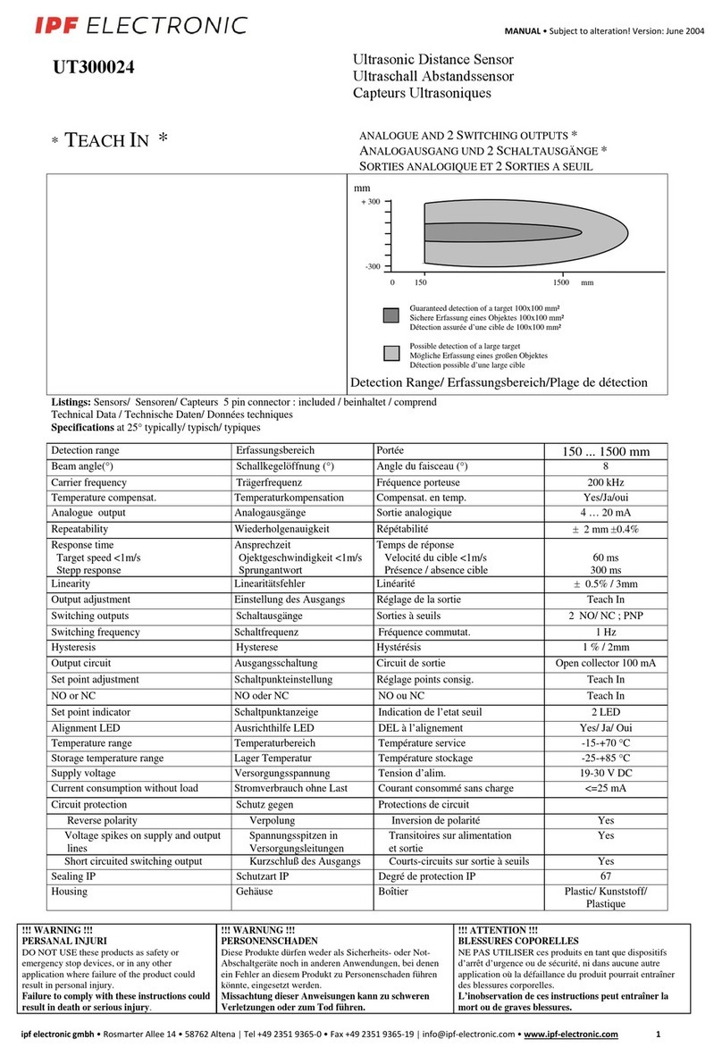
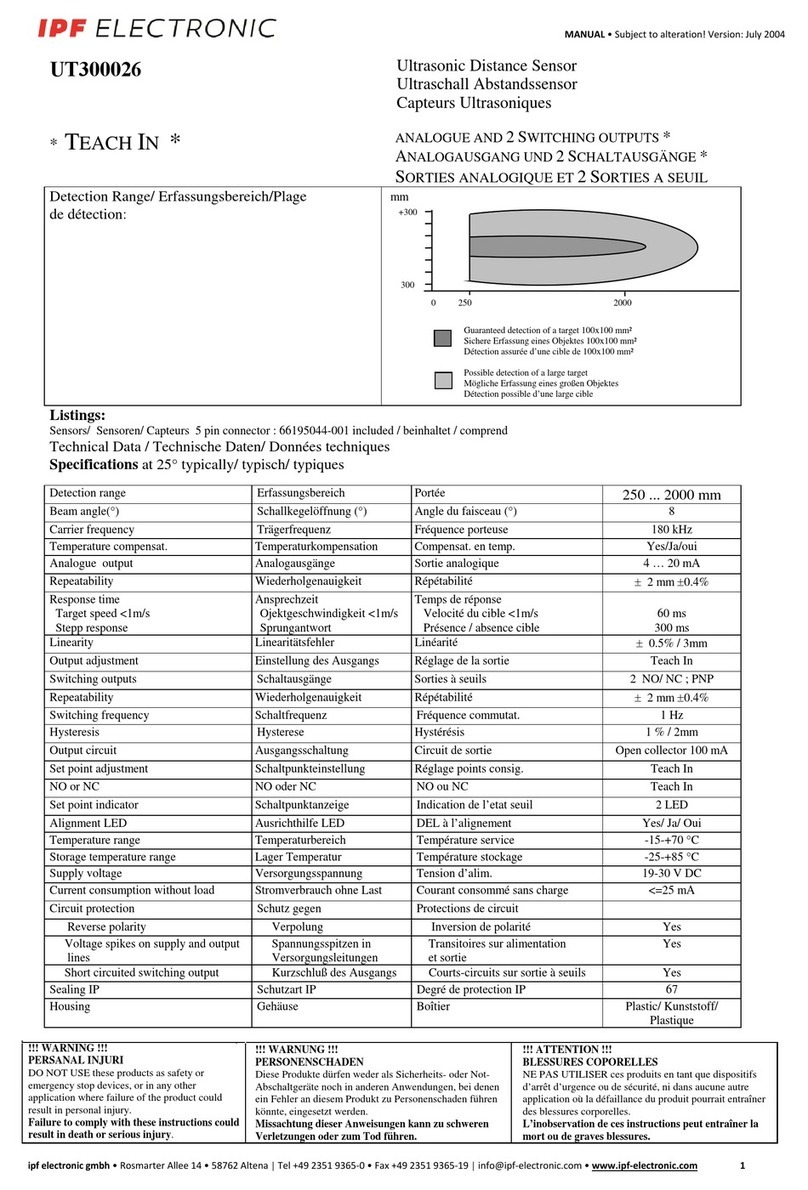
ipf electronic UT300026 User manual

ipf electronic
ipf electronic UT300024 User manual

ipf electronic
ipf electronic UT139573 User manual

ipf electronic
ipf electronic OY36 User guide

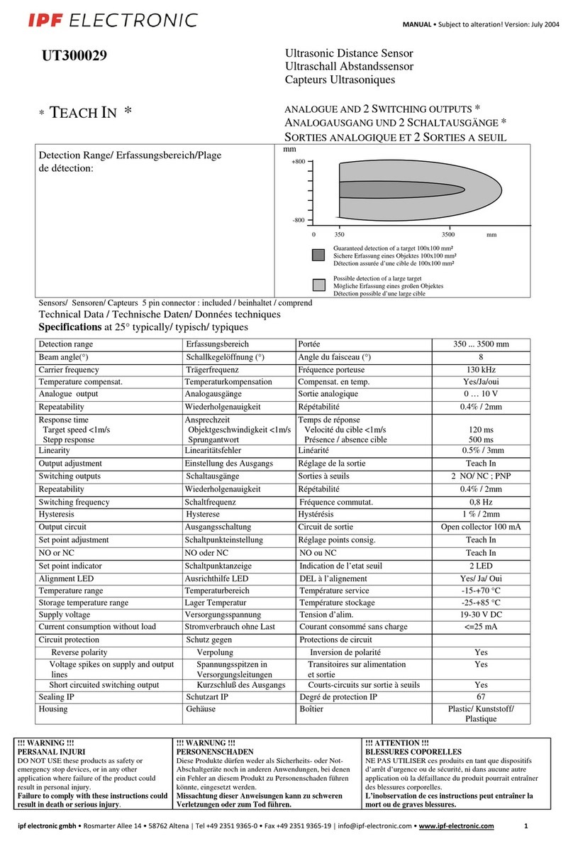
ipf electronic
ipf electronic UT300029 User manual

ipf electronic
ipf electronic UT990895 User manual

ipf electronic
ipf electronic UY000001 User manual

ipf electronic
ipf electronic UT300028 User manual

ipf electronic
ipf electronic UT18002E User manual

ipf electronic
ipf electronic PT740020/21 User manual