Locca Sure-Touch Manual

Locca Sure-Touch
User and Installation Guide

Contents
1 Introduction
1 Locca Sure-Touch features
2 Locca Sure-Touch pack contents
3 Before you start…
4 How to personalise your system
4 Setting the Time Delay function
5 Erasing Locca Remote Keys
5 Learning Locca Remote Keys
6 Warning Alerts on your
Locca Receiver
– Power Cut Alert
– Battery Low Alert
– Door Open Alert
7 Installation
11 Guarantee
11 Technical Data
12 Terms and conditions
14 Contact details

Introduction
The Locca Sure-Touch system is an
innovative secure remote locking
system that will enable you to access
your property at the touch of a button.
Operation and programming of the system have
been specifically designed for ease of use:
• All features of the Sure-Touch can be quickly
understood
• Programming of the system has been designed
with simplicity in mind – you will need no
technical knowledge to operate the system.
Behind this simple interface lies the latest
technology – your system incorporates high-
security code-hopping technology. Each time
your Locca Remote Key is pressed, a one in
4.6 billion encrypted code is emitted. The next
time the Locca Remote Key is pressed, this
code will have changed to a new random one
in 4.6 billion code.
Locca Sure-Touch User Guide | 1
Locca Sure-Touch
features
• Simple operation
• User-friendly programming
• Attractive ergonomic design of Locca Remote
Keys offering unparalleled ease of operation
• Long-life rechargeable battery
• Audible and visual low battery warnings
(for both the Remote and the Receiver)
• Indication of power cut or drop in power
supply (the system will continue to operate
on the backup battery in the event of power
failure for at least 48 hours in standby mode)
• Superior transmission range
• Your Locca Remote Key has been designed
for ease of use. It has been shaped to fit
comfortably and easily in your hand and
gives you the option to carry it on your wrist
or wear it around your neck
• Wall-mounted bracket enables positioning
of the Locca Receiver in the most convenient
location, for optimal use around the house.

Your Locca Sure-Touch
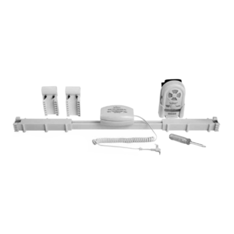
pack contains:
2 | Locca Sure-Touch User Guide
Locca Receiver Wall-mounting bracket Rechargeable battery
Locca Master Key
(Red button)
2 x Locca Remote Keys
(Yellow button)
Transformer
2 x plugs and screwsLocca wrist band
Locca neck band

Locca Sure-Touch User Guide | 3
Receiver
pins
Before you start…
You must connect the backup battery
to the Locca Receiver:
3. Replace battery cover and
secure with screw
4. Once in place the Locca Receiver
will beep to confirm the system
is working
1. Unscrew battery cover
2. Connect battery
to Locca Receiver
Back view of Locca Receiver
Back view of Locca Receiver
Unscrew
battery
cover here
Battery
lead

4 | Locca Sure-Touch User Guide
How to
personalise
your system
The following programming features
can be simply carried out:
1. Setting the Time Delay
How long do you want the release
mechanism to stay open on pressing
the Locca Remote Key?
2. Erasing Locca Remote Keys
How do you erase Remote Keys
if lost or stolen?
3. Learning Locca Remote Keys
How do you add extra Remote Keys
to the system?
1. Setting the Time
Delay function
Please note: The Time Delay is the amount of time the
electric door release will remain unlocked. This can be
cancelled before the delay period ends with a second
press of your Locca Remote Key.
The system is pre-set for five seconds. This may
be what you want. If not and you would like to
personalise you entry time then follow the
steps below:
1. Press the Locca Master Key. This will activate
the Locca Receiver and prepare it for future
instructions.
The Locca Receiver will begin to beep and an
orange light will flash to indicate the system is
ready to move on to Step 2.
2. Now press and hold down the ‘delay’ button
on the Locca Receiver. The amount of time the
‘delay’ button is held down will be the amount
of time that the delay will be set for (i.e. if you
hold the button down for 10 seconds, the delay
will be set for 10 seconds).
While the ‘delay’ button is held down, the
Receiver will beep every second to confirm each
second registered. At the same time, a visual
green flash will be seen on the top Receiver light
for each second registered (i.e. if you hold
the button down for 10 seconds, the system
will beep 10 times during this period and flash
10 times, to indicate that the delay has been
set for 10 seconds).
When the ‘delay’ button is released the system
will confirm the time you have set the delay
for. The Receiver will beep quicker and flash
quicker for the period of time the delay is set
for (i.e. you will hear beeps and see flashes for
the duration of the delay).

Locca Sure-Touch User Guide | 5
2. Erasing Locca
Remote Keys
If you have lost a Locca Remote Key or perhaps
think one has been stolen, the solution is simple.
1. Press the Locca Master Key. This will activate
the Locca Receiver and prepare it for future
instructions.
The Receiver will begin to beep and an orange
light will flash to indicate the system is ready to
move on to Step 2.
2. Now press and hold down the ‘erase’ button
for three seconds until the Locca Receiver
beeps three times. The red light will also flash
three times.
3. On releasing the ‘erase’ button, the system will
emit two long beeps and give two long flashes
to confirm that your Locca Remote Keys have
been deleted.
4. If you release the ‘erase’ button before the
three-second duration has expired, no action
will be carried out and the Locca Receiver will
return to its normal state.
Please note: On completion of the ‘erase’ function,
ALL LOCCA REMOTE KEYS WILL BE ERASED.
You can now simply reprogram your Locca Remote keys.
3. Learning Locca
Remote Keys
To add new Locca Remote Keys or to reprogram
original Locca Remote Keys that have been erased,
follow the simple instructions below.
Please note: a total of 13 Locca Remote Keys – in addition to
your Locca Master Key – can be programmed to the system.
1. Press the Master Key ONCE. This will activate
the Receiver – the Receiver will begin to beep
and an orange light will flash.
Press the Master Key a SECOND TIME.
Wait for the receiver to change to LEARN MODE:
the middle light will turn green and the beeps will
quicken, indicating the system is ready to move
on to Step 2.
2. Press the button on the Locca Remote Key you
wish to activate ONCE.
There will be no change in sound or light signals.
Press the Locca Remote Key a SECOND TIME.
There will be a long beep and a long flash to
indicate that the new Locca Remote Key has
been programmed.
Please note: If you ‘learn’ more than 13 Locca Remote
Keys into the Receiver memory, the last Locca Remote Key
programmed into the system will be automatically deleted.
Please note: On learning a new Locca Remote Key,
the middle green light will flash every 5 seconds for
48 hours to indicate that a new Remote Key has been
added. This is a security measure.
If you have not added a Remote Key during that period,
Locca recommends that you ‘Erase’ all and start again.

Warning Alerts on
your Locca Receiver
Power Cut Alert
The Locca Receiver is equipped with a
backup battery in case of an interruption to
normal power supply (such as a power cut).
The Locca system is designed to operate
for a minimum of 48 hours in standby mode
during a cut to the power supply.
In the event of an interruption in power,
all lights on the Locca Receiver will immediately
flash and a warning sound will simultaneously
be emitted for 15 seconds. Thereafter, a five-
second beep, accompanied by flashing lights
on the Receiver, will occur every 60 minutes.
If for any reason the system is unplugged at
the mains, the system will wait 60 seconds,
then emit a 15-second beep as above.
Battery Low Alert
The Locca Receiver
Should the battery in the Locca Receiver
run low, the Locca system will alert you. A red
warning light on the Receiver will be illuminated
and a five-second audible signal will sound
every 60 minutes.
The Locca Remote Key
Should the battery in your Locca Remote Key
run low, the Locca system will alert you. This
alert will be activated each time you use your
Locca Remote Key. A low battery reading
from the Locca Remote Key will activate
an alternating orange and green flash on the
Locca Receiver.
Please note: If the battery runs low on the Locca Remote Key,
please contact Locca on 0870 240 5074 to order a new Locca
Remote Key).
Door Open Alert
When you press your Locca Remote Key and
activate the electric door release, the
Locca Receiver will signal the ‘door open’ state.
The middle green light on the Receiver will be
illuminated for the duration of the ‘door open’ state.
There are also three choices of audible signal:
1. A continuous beep for the duration
of the ‘door open’ state
2. A series of beeps for the duration
of the ‘door open’ state
3. No audible signal.
When you receive your Locca system, the
default setting is a continuous beep that lasts
the duration of the ‘door open’ state. To change
this, simultaneously press the ‘erase’ and ‘delay’
buttons on the Locca Receiver. Each time you
press these together, the Receiver scrolls
through the sound options:
Continuous beep > Intermittent beeps >
No sound alert > Continuous beep… etc.
6 | Locca Sure-Touch User Guide

Locca Sure-Touch User Guide | 7
Installation
This section assumes you are
intending to use the electric door
release recommended with the Locca
Sure-Touch, or another similar 12VDC
access-control mechanism that will
operate on a standalone basis with
the Locca Receiver.
For other scenarios, see the next section
on page 9.
Should you at any time need to change the
wiring from the terminal block on the Locca
Receiver, the screws on the terminal block can
be accessed by removing the battery cover
(see page 3).
Step 1
Choose where you are going
to position the Locca Receiver
Please note: The Locca Receiver should either be positioned
within reach of a mains power point or a qualified electrician
should be employed to wire it into the mains. Before attaching
the Receiver to the wall, ensure that it is in a location where
signals will be received from Locca Remote Keys.
It is normally best to position the Locca Receiver
close to the door so that the Locca Remote Keys
have the best possible range outside the house.
The range of the Locca Remote Keys is normally
around 50m, depending on the environment, so you
have some flexibility. Make sure that the wire from
the plug-in power supply can reach the Receiver.
Once you have chosen where you intend to position
the Receiver, leave it in this location WITHOUT
FIXING IT and plug the Receiver in.
Now check that the Remote Keys operate the
Receiver from everywhere required both inside
and outside.
(It is advised that Receivers are not installed on
metal screening surfaces nor in the vicinity of other
objects or electronic devices that may reduce the
operating range of the system.)
The middle green lamp will light when the Receiver
is activated from a Remote Key. If you have not
changed the sound settings*, the Receiver will emit
sound for the period that the door opener is operating.
You may want another person to walk around with
the Locca Remote Key while you watch the
Receiver.
* To change sound settings, see page 6:
Door Open Alert

8 | Locca Sure-Touch User Guide
Step 2
Install the electric door release
into the door frame
Run the pre-installed wire from the Locca
Receiver to the electric door release. Attach
the wire to the door release. If the pre-installed
wire has been removed from the Locca Receiver
for any reason, carry out the following:
• Reveal the two conductors in the wire and use
a jeweller’s screwdriver to connect them to pins
5 and 6 of the connection block at the bottom
of the Receiver. It does not matter which way
round you connect the leads
• Connect the two connectors on the electric
door opening mechanism
• Pins 2 and 3 should be linked by the short wire
that is in place when you obtain your Receiver.
Ensure that this is the case.
Install the door release to the door frame,
as described in the separate instructions
(these are in the Electric Door Release packaging).
Step 3
Mount and plug in the
Locca Receiver
Screw the metal mounting plate onto the wall using
the screws and plugs provided. Slot the Receiver
onto the mounting plate.
There is a screw at the base of the Receiver that
you may tighten to prevent the Receiver being
lifted off the mounting plate.
Your Locca system is now installed.
If you need to personalise your system you may
do so now (see page 4: How to personalise
your system).
Screw metal
mounting plate
to wall
Tighten
screw at base
of Receiver
654321
Pre-installed wire
should be connected
direct to connectors
on electric strike
Pre-installed
wire link
Locca Receiver

Locca Sure-Touch User Guide | 9
Step 4 i)
The most common requirement is to allow the
Locca Receiver to also operate a door release that
is operated by an intercom or other system where
you press a button to release the door.
Adding the Locca Receiver allows you to use the
Locca Remote Key to release the door from outside
or around the inside of your home.
Check with the instructions or manufacturer that
the existing buttons are normally open low-voltage
switches (up to 24V).
Remove the link that is pre-installed between pin
2 and pin 3 of the connection block at the bottom
of the Receiver. Then connect pin 3 and pin 5
across (in parallel) an existing switch. You can
do this at a connection block either in the central
intercom controller or at one of the handsets.
These pins are connected by a relay when a
Locca Remote Key is operated.
Step 4
Using alternative electric door
releases
You can also use your Locca Receiver to operate
an entry-phone, intercom, keypad, electric or
magnetic door release system.
You are advised to use an electrician to ascertain
how the existing release is switched and to make
this connection.
The terminal block can be accessed by removing
the battery cover (see page 3).
Back view of Locca Receiver
Rechargeable
battery
Screws for
terminal
654321
Intercom system
Existing button
to release door
Locca Receiver

10 | Locca Sure-Touch User Guide
Step 4 ii)
If you need to interrupt a normally closed circuit
or switch, such as for a low-voltage magnetic
door closure:
• Remove the link that is supplied between pin
2 and pin 3 of the connection block at the
bottom of the Receiver
• Then connect pin 3 and pin 4 in series with
the existing switch or circuit.
Please note: the system has been designed to work
in conjunction with existing systems with a maximum
voltage of 24V and current of 1 Amp.
Step 4 iii)
For any other arrangement, for example to switch
a mains voltage circuit on or off, you can connect
an appropriately rated relay with a 12V coil to pins
5 and 6 of the connection block at the bottom of the
Receiver, leaving the link which supplies 12V from
pin 2 to pin 3 in place.
The system has been designed so that you could
even use a double pole double throw relay to
momentarily disconnect an existing 12V strike
circuit and operate it with power from pin 3.
The diagram below explains the pins on
the connection block at the bottom of the
Locca Receiver.
Maximum voltage 24V.
Under no circumstances should mains voltage
connections be made directly to the terminal block.
654321
Existing circuit
Locca Receiver
65432
0V 12V
1
Output contacts shown
in standby condition

Locca Sure-Touch User Guide | 11
Important
The user should not attempt
to service the unit or open the
main casing.
All servicing should be referred
to qualified personnel.
Changes or modifications to the unit may void
the user’s authority to operate the equipment
and will nullify the warranty.
Guarantee
Your Locca system comes
with a free one-year guarantee
(from date of purchase) against
mechanical and electrical defects.
This guarantee is only valid if the appliance is
used in accordance with the instructions provided,
and is not connected to an unsuitable electricity
supply, dismantled or interfered with in any way
or damaged through misuse.
Under this guarantee we undertake to replace
free of charge any Locca Sure-Touch system
found to be defective.
Nothing in this guarantee or the instructions
relating to the product excludes, restricts or
otherwise affects your statutory rights.
In line with our policy of continuous development,
we reserve the right to change this product,
packaging and documentation without notice.
Technical Data
Adaptor Supply 12Vdc 300mA
(Centre positive)
Output 12Vdc 300mA
External Input max. 24Vdc 1A
Max. Switching 24Vdc 1A
Ambient temperature range 0º to 40ºC
Environment humidity 80% RH
Battery
If replacing the battery or disposing of the
equipment, the battery must be removed
and disposed of safely at a re-cycling or
other collection centre.

Contact details
For more information or to purchase
additional accessories, please visit our
website or call the order line.
Locca Tech Limited
PO Box 1, Basildon, Essex SS15 6TZ
Locca is a trademark of Locca Tech Limited. All rights reserved. PKG0WDES07A
Table of contents
