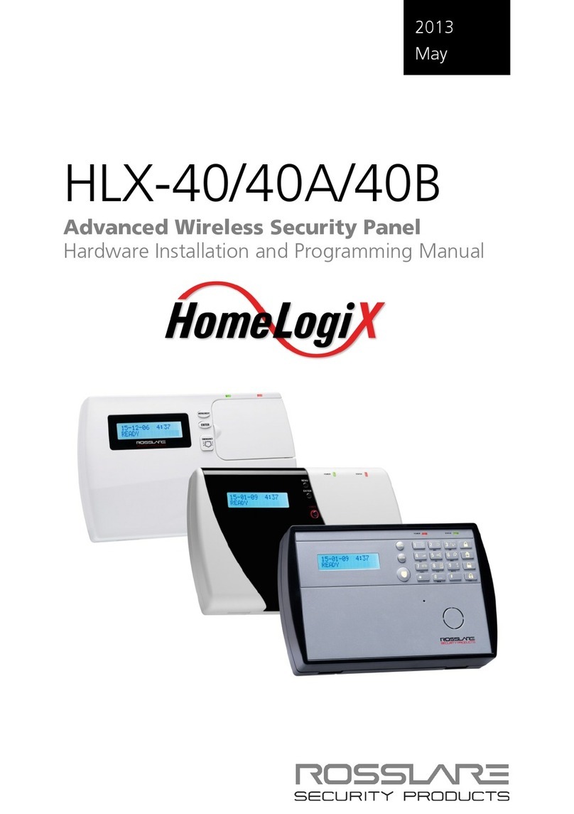
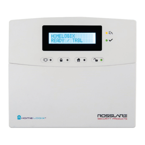
Rosslare HLX-40 User manual

HLX-40/40A/40B
Advanced Wireless Security Panel
User Manual
September 2010


Table of Contents
HomeLogiX, HLX-40 User Guide
Page ii
Table of Contents
1. Introduction............................................................. 4
2. Operating the HLX-40 .............................................. 6
2.1 Quick Reference.................................................................. 6
2.2 About Everyday Operation .................................................. 6
2.3 Arming Options.................................................................... 6
2.3.1.Arm Away .......................................................................................... 6
2.3.2.Arm Home ......................................................................................... 7
2.3.3.Disarmed........................................................................................... 7
2.3.4.Quick Arming ..................................................................................... 8
2.3.5.Instant Arming.................................................................................... 8
2.3.6.Forced Arming................................................................................... 8
2.4 Entry/Exit Delay Options........................................................ 8
2.4.1.Entry Delay......................................................................................... 8
2.4.2.Exit Delay ........................................................................................... 9
3. Technical Specifications........................................ 10
4. System Overview ................................................... 12
4.1 HomeLogiXTM HLX-40 Wireless Panel .................................. 12
4.2 The LCD Display ................................................................. 13
4.3 The Keypad ....................................................................... 14
4.4 Sound Indicators................................................................ 17
4.5 LED Indicators .................................................................... 18
5. User Menu Structure............................................... 19
6. VIP Menu .............................................................. 21
6.1 General ............................................................................. 21
6.2 Arming submenu ............................................................... 22
6.3Automation Submenu ....................................................... 22
6.4 Voice Operation Submenu ............................................... 22
6.5 Status Report...................................................................... 23
7. READING THE EVENT LOG ....................................... 24
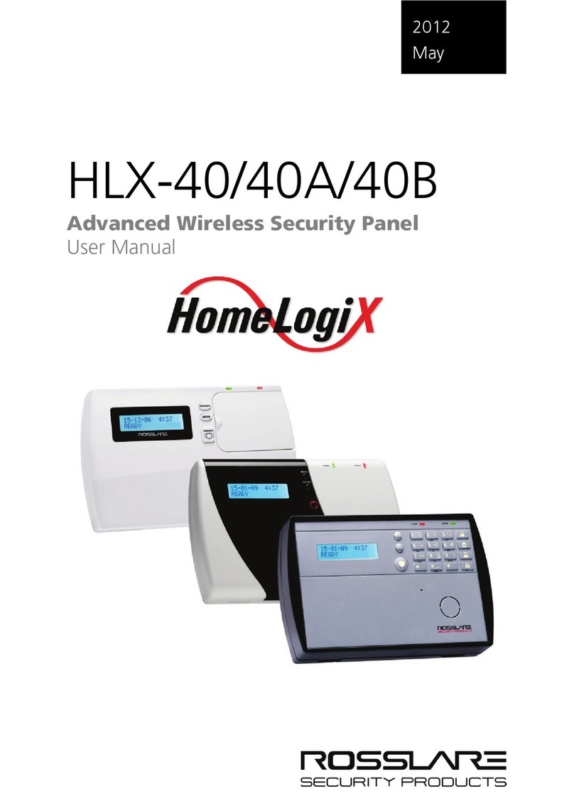
Table of Contents
HomeLogiX, HLX-40 User Guide
Page iii
8. SMS Commands ................................................... 25
9. User Menu Options ................................................ 26
9.1 Accessing the User Menu .................................................. 26
9.2 Changing the Master Code .............................................. 26
9.3 Defining User Codes .......................................................... 26
9.4 Setting Date and Time....................................................... 27
9.5 Defining Date and Time Format ........................................ 27
9.6 Setting Zone Bypass ........................................................... 28
9.6.1.Enabling Zone Bypass ...................................................................... 28
9.6.2.Defining Bypass Zones ..................................................................... 28
9.7 Enrolling Remote controls .................................................. 29
9.8 Setting Phone Numbers ..................................................... 30
9.9 Activating / Deactivating PC Mode................................... 30
10.Maintenance ........................................................ 31
10.1 Dismounting the Control Panel.......................................... 31
10.2 Replacing the Backup Battery ........................................... 31
Appendix A. Limited Warranty .................................... 32
Appendix B. Declaration of Conformity ...................... 34
Appendix C. Technical Support .................................. 35

Introduction
HomeLogiX, HLX-40 User Guide
Page 4
1. Introduction
The HomeLogiXTM
Users receive the latest RF technology in a wide selection of
advanced wireless sensors and remotes, and benefit from
smooth and easy operation of a large number of security and
communication options.
HLX-40 family of panels by Rosslare is the
perfect wireless security system for intrusion protection of the
home, or small office providing security monitoring and VIP
Voice messaging.
The Panel has two full split reporting features for
communicating to central station for Contact ID + 2-Way
Voice Enabled event reporting and vocal communications.
VIP features include Voice Assist, where the panel uses voice to
prompt the user, Private Messaging to three destinations, with
an optional 2-way voice session for every message.
The HomeLogiXTM
•HLX-40
HLX-40 family comes in three attractive
designs:
•HLX-40A
•HLX-40B
Figure 1 HLX-40

Introduction
HomeLogiX, HLX-40 User Guide
Page 5
Figure 2 HLX-40A
Figure 3 HLX-40B

Operating the HLX-40
HomeLogiX, HLX-40 User Guide
Page 6
2. Operating the HLX-40
This section comes to describe the day to day operation of the
system as well as provide a quick reference for the Arming /
Disarming buttons in the system
2.1 Quick Reference
Use the following buttons on the keypad for quick arming the
system:
AWAY Arms all sensors and detectors for use when
there is no one at home/office.
HOME
Arms all perimeter sensors and detectors as
defined by the installer. For use when
home/office is occupied.
DISARM
Disarms all armed sensors and detectors.
ESC
Ignore an entry or move one level up in a
menu ESC arms the system.
For more on the keys and their function see section The
Keypad on page 14.
2.2 About Everyday Operation
The HLX-40 system allows you to insure the security of your
home—both while you are home and while you are away. The
system allows you to control attached sub-systems and
appliances such as garage doors, lights, heating, air
conditioner, and more via an expandable PGM output.
2.3 Arming Options
Based on the way the system is configured by the installer the
below arming options are available:
2.3.1. Arm Away
Full arming of the system, best used when there is no one at
home / office. In AWAY mode, the system enters Alarm mode if

Operating the HLX-40
HomeLogiX, HLX-40 User Guide
Page 7
there is a zone violation—regardless of perimeter or interior
type.
To arm the system using Away:
1. Verify that the system is ready for arming.
2. Press the Away
3. Enter your user code.
arming key.
2.3.2. Arm Home
Home arming is a perimeter arming of all perimeter sensors and
detectors as defined by the installer. For use when home /
office is occupied.
To arm the system using Home:
1. Verify that the system is ready for arming.
2. Press the Home
3. Enter your user code.
arming key.
2.3.3. Disarmed
When disarmed, the HLX-40 system enters Alarm mode for
each 24 hour zone. Alarms will trigger only for panic,
emergency, fire, 24H audible and silent conditions.
In this state, the system continuously checks zone status and
will hold the Ready status parameter. This parameter
determines whether the system is ready to arm. The system will
become Ready to Arm when zones are either closed or
bypassed, or force arming is enabled.
To disarm the system:
1. Press the Disarm
2. Enter your user code.
key.

Operating the HLX-40
HomeLogiX, HLX-40 User Guide
Page 8
2.3.4. Quick Arming
Quick arming allows arming the system without code entry. If
Quick Arming is enabled (by the installer during setup), a long
press on one of the arming buttons activates Quick Arming.
2.3.5. Instant Arming
If Instant Arming mode is enabled (by the installer, during
configuration), the system will skip the exit delay as well as
cancel the entry delay configured, and will initiate the Alarm
instantly causing an alarm to go off upon violation of any zone.
To instantly arm the system:
1. Verify that the system is ready for arming.
2. Press either the Home or the Away
3. Enter your user code. arming key.
4. Press the same arming key once again.
2.3.6. Forced Arming
If Forced Arming is enabled, the system is able to arm even
when zones are in violation (open) but not defined as
bypassed. In such a case, the system will arm, effectively
bypassing the open zone. Once the open zone is closed the
system will complete arming, adding the previously bypassed
zone to the monitored zones.
2.4 Entry/Exit Delay Options
Entry and Exit actions delay the alarm mode and allow the
system to ignore zone violations, as described below.
2.4.1. Entry Delay
Entry delay allows the user a grace period for the time it takes
him to open the door and reach the keypad. It is the time
allowed to the user to reach the keypad to disarm the system.

Operating the HLX-40
HomeLogiX, HLX-40 User Guide
Page 9
If a zone of type Delay is violated while the system is armed
(except Instant Arming), the system does not enter Alarm
mode during the Entry Delay period setting. If the delay has
transpired and the system still has not been disarmed, the
system enters Alarm mode.
During Entry Delay, the system signals the keypads to sound
warning beeps at two rates: slower rate and faster rate during
the last 10 seconds of the delay period.
2.4.2. Exit Delay
Exit delay allows the user a grace period for the time it takes
him to reach the door from the keypad when arming the
system upon exit.
When arming a panel, the system ignores zone violations of the
predefined delay zones during the Exit Delay period. Once the
delay has transpired, the system enters armed mode.
Note:
During HOME arming the system will ignore all interior
zones as well as the predefined delay zones.
The system may be disarmed during the Exit Delay period.
During Exit Delay the system emits warning beeps at two rates:
slower rate followed by a faster rate of beeping during the last
10 seconds of the delay period.

Technical Specifications
HomeLogiX, HLX-40 User Guide
Page 10
3. Technical Specifications
Electrical Characteristics
External Power Supply
220VAC / 50Hz, 110VAC / 60Hz
Operating Voltage
Range
13.8VDC, 800mA
Input Current
Standby: 120mA
Max: 500mA(1000mA w/GSM
expansion)
Internal backup
battery:
800mAh for 6 hours standby, 2 hours full
alarm
Auxiliary power output:
12VDC, 500mA max
Display
Two Line, 16 characters, white backlit
LCD
PGM open collector
outputs
Two fully programmable, 200mA, PTC
protected
External Siren output
1A relay
Local Siren
80dbA
Communication (RF) Characteristics
Frequencies
433.92MHz (G version)
868.35MHz (H version)
RF Jamming detection
UL / EN selectable
Anti-collision
Proprietary RF protocol
Programmable no-activity
timer
1-30 hours, per zone
Reporting
Three private telephone
numbers.
Two-Way voice
communication
Three private telephone
numbers
Telephone and modem
Built in dialer & 2400 Baud
modem

Technical Specifications
HomeLogiX, HLX-40 User Guide
Page 11
Environmental Characteristics
Operating Temp. Range
32º F - 140º F (0º – 60º C)
Storage Temp. Range
-13º F - 158º F (-25 º – 70º C)
Operating Humidity
0– 85% at 30ºC non-condensing
Dimensions
HLX-40
HLX-40A
HLX-40B
Height x Width
x Depth 217 x 144 x 48
mm
8.54 x 5.67 x
1.89 Inch.
217 x 144 x 50
mm
8.54 x 5.67 x
1.97 Inch
217 x 144 x 48
mm
8.54 x 5.67 x
1.89 Inch
Weight
217 x 144 x 48
mm
8.54 x 5.67 x
1.89 Inch.
217 x 144 x 50
mm
8.54 x 5.67 x
1.97 Inch
217 x 144 x 48
mm
8.54 x 5.67 x
1.89 Inch

System Overview
HomeLogiX, HLX-40 User Guide
Page 12
4. System Overview
The main components of the HomeLogiXTM HLX-40 wireless
panel are:
HomeLogiXTM ,HLX-40 Wireless Panel below
•The LCD Display, on page 13
•The Keypad, on page 14
•Sound Indicators, on page 17
•LED Indicators, on page 18
4.1 HomeLogiXTM
The following describes the components of the wireless panel.
HLX-40 Wireless Panel
Figure 4 Components
The table below describes the components in the panel:
Menu
Use to navigate between menus.
Power indicator
Power LED: Red On: system is ON.
FLASHING: AC power failure
Power
Indicator
Display Status
Indicator
Keypad
Door
HLX-40
and
HLX-40A
Local sounder
Local Emergency
Button
Microphone
Menu
Enter

System Overview
HomeLogiX, HLX-40 User Guide
Page 13
Status indicator
Status LED: green On: system armed.
Off: system disarmed.
Flash: entry and exit delay (according to
beep rate)
Keypad door
Open to access the keypad buttons
Local sounder
System speaker
Microphone
Enables the recording of voice messages
Local emergency
button
Keep pressed for 3 seconds to sound a
standard panic alarm
Display
LCD display
Enter
Accept an entry or selection
4.2 The LCD Display
The LCD display clearly shows the system status. The display
consists of two rows. The bottom line is divided into two and
displays the system status and events.
When in idle mode the first line displays the system's name
(HomeLogiX by default) while the second line shows the system
status. For example, the second line displays Ready
Pressing .
#
The system status is displayed on the left of the bottom line. The
events are displayed on the right of the system status. If there is
more than one event, the event display toggles every two
seconds. There are several display options as described below:
(pound key), toggles the first line display between
the System name display and the Time & Date display.
System Status
Ready
Indicates that the system is ready for arming.
Not ready
Indicates that the system is not ready and that there are
active zones.
Press Enter to see which zones are active. If there is more
than one active zone pressing Enter or Menu
When there are no more active zones the display returns
to the idle view. You can also exit the active zone view
by pressing the
displays the
next open zone.
ESC, Away or Home buttons.

System Overview
HomeLogiX, HLX-40 User Guide
Page 14
Event Display
TRBL
Indicates that a problem exists on the system. The
following System Troubles may appear in the TRBL
•Battery Missing
message:
•Dead Battery
•Low battery
•Power failure (AC Fail)
•RF jamming
•Line Fail
•Communication Fail
•Tamper
In addition the following Zone Troubles may appear in
the TRBL
•Tamper
message:
•Low battery
•Short Wire
•Supervision (failure)
MEM
Indicates an alarm in memory.
MSG
Indicates that a personal message is waiting.
4.3 The Keypad
The keypad is used to program the wireless panel and to arm
and disarm the sensors.
Figure 5 The Keypad

System Overview
HomeLogiX, HLX-40 User Guide
Page 15
The following table describes the keypad functions:
Key
Press to
Menu
Navigate between User and Installer menus,
and Normal mode.
Navigate to the next menu or the next
option within a menu.
Enter
Accept an entry or selection.
Local
Emergency
When pressed for 3 seconds a standard
panic alarm Sounds
AWAY
Arm all sensors and detectors. Use this
function when there is no one in the
home/office. You must enter a user or
master code.
HOME
Arm all perimeter sensors and detectors as
defined by the installer. Use this function
when the home/office is occupied. You
must enter a user or master code.
DISARM
Disarm all armed sensors and detectors. You
must enter a user or master code.
If the duress code is enabled by the
installer, entering the duress code when
disarming sends a duress event to the
Central Station and Private Phone.
The system will lockdown for 30 seconds in
the event of 5 failed attempts to disarm the
system
ESC
Press to ignore an entry (escape) or to
move one level up in a menu.

System Overview
HomeLogiX, HLX-40 User Guide
Page 16
Key
Press to
0
normal
mode only
Press once to display the alarms caused
during the last arming period per zone. The
first line of the displays shows the alarm
memory, and the second line shows the
zone description, event and time.
Memory Display
Press Enter
Press
to toggle view between zone
description and the Time & Date.
Menu
Press to display the next event.
Esc
You can also use
to exit. 0
1
normal
mode only
to insert a space when
typing an entry.
PGM ON
Press once to enter PGM activation mode,
the PGM status is indicated on the right.
Press
- if enabled by installer
1to activate PGM 1 and/or 2
2
normal
mode only
to
activate PGM 2.
PGM OFF
Press once to enter PGM deactivation
mode, the PGM status is indicated on the
right. Press
- if enabled by installer
1to deactivate PGM 1 and/or 2
3
normal
mode only
to deactivate PGM 2.
Manually toggle the chime on and off (if
enabled by the installer) The default is off.
Chime ON/OFF
4
normal
mode only
Manually Adjust the system’s volume level.
Volume
5
normal
mode only
Sound ON/OFF
Manually toggle voice messages, keypad
tone, and other sounds on and off.
(except
for trouble beeps, forced arming,
enrollment and RF test of wireless devices
which is always on)
- if enabled by installer
6
normal
mode only
Bypass
Enter the last User menu Bypass option to
arm the system by bypassing active zones.
You must enter a user or master code.
- if enabled by installer

System Overview
HomeLogiX, HLX-40 User Guide
Page 17
Key
Press to
7
normal
mode only
Record a voice message of up to fifteen
seconds. Press and hold the
Record User Message
7
8
normal
mode only
key for three
seconds to erase a message.
Press once to display the event log. The first
line of the display shows the event log (for
example
Event Log Display
Burglar Alarm
Press
). The second line
shows the zone description or system.
Enter
Press
to toggle view between zone
description and the Time & Date.
Menu
Press to display the next event.
Esc
You must enter a master code.
to exit.
9
normal
mode only
Listen to voice messages.
Play User Message
4.4 Sound Indicators
Following are the sounds emitted by the system and keypad:
Sound
Sounded when
Single beep
A key is pressed
Long Beep
Illegal key entry
Three short beeps
An entry is successfully accepted.
Four short beeps
a minute
If enabled, on trouble condition.
Short beep every
second
An exit/entry delay is activated. (Beep sounded
every 0.5 seconds during last 10 seconds of delay.
Chime 1 & 2
Two (2) various chime sounds, when feature is
activated
Chime 3
Vocal announcement of “Zone Name” + Open
Aside from the indication sounds the system also has a voice
confirmation of various events.
Note:
This table does not include actual alarm sounds.
Note that the audible indication of a fire zone differs
from that of a normal intrusion zone.

System Overview
HomeLogiX, HLX-40 User Guide
Page 18
4.5 LED Indicators
This section describes the LED indicators of the power and
status indicators
LED
Behavior
Power
LED
Red
On when the system is ON. FLASHING When there is
an AC power failure.
Status
LED
Green
OFF when system is disarmed ON when system is
armed. FLASHING during entry/exit delay, according to
the beep rate specified

User Menu Structure
HomeLogiX, HLX-40 User Guide
Page 19
5. User Menu Structure
The User menu enables the configuring of the basic user
settings, such as setting the date and time, and changing user
codes. You can define one master user and up to twenty
additional users, each with their own code.
Settings marked with an (M)
can be accessed by the master
user only, and appear only if the master code is entered.
Note:
If the master code has not been specified, and the
installer has set the zone bypass to Off
, the User menu is
unavailable to regular users.
To enter the User menu:
5. On the panel, press Menu repeatedly until the screen
displays User
6. Press .
Enter
7. Enter the master user code (the default code is 1234) and
press
.
Enter
. The User menu options are displayed:
Note:
The system will lockdown for 30 seconds after entering 5
wrong codes.
Select
To
(M) Edit Master
Code
Change the master code (more on page 26).
(M) User
Codes
Specify user codes 1 through 20.
If the user code exists, you can edit the code or
delete it by pressing #on page 26(more ).
(M) Set Date &
Time
Set the Time & Date, as specified in Setting Date
and Time, on page 27.
(M) Date &
Time Format
Specify the format in which the time is specified:
24 hour format or AM/PM. By toggling between
the two using the Menu
Specify the format in which the date is specified:
DD-MM-YY or MM-DD-YY (more
button.
on page 27)
Other manuals for HLX-40
6
This manual suits for next models
2
Table of contents
Other Rosslare Security System manuals

Rosslare
Rosslare AuraSys L-4 User manual

Rosslare
Rosslare HLX-40 User manual

Rosslare
Rosslare HLX-40 User manual

Rosslare
Rosslare HLX-40 Assembly instructions

Rosslare
Rosslare HLX-40 User manual

Rosslare
Rosslare HOME LOGIX HLX-24 Assembly instructions

Rosslare
Rosslare AuraSys L-2 Assembly instructions

Rosslare
Rosslare HLX-40 User manual

Rosslare
Rosslare AYC-Q65 Assembly instructions

Rosslare
Rosslare SA-95 User manual