Locinox TURNITEC 3 User manual

TURNITEC 3
TURNITEC 4
NEDERLANDS
USER GUIDE ENGLISH
DEUTSCH
FRANÇAIS

• As manufacturer of this product, we guarantee that we have
taken all the necessary steps in order for this product to comply
with the current safety requirements.
Copyright
Copyright © 2021 Locinox. All rights reserved.
This product incorporates copyright protected technology that is protected by a number of EU
patent method claims and other intellectual property rights owned by the Locinox Corporation
and other rightholders.
Use of this copyright protected technology must be authorized by the Locinox Corporation.
Reverse engineering or disassembly is prohibited. No part of this publication can either be
reproduced, communicated, transcribed, stored in a retrieval system or be translated into any
language in any form or by any means, whether electronic, mechanical, magnetic,
optical, chemical, manual or otherwise, unless explicit written consent has been given by the
copyright holder.
Notice
The contents of this publication is subject to change. The company reserves the right to alter the
contents of this publication at any time and without notice. The contents of this publication may
contain inaccuracies or typographical errors and is supplied forinformational use only.
Technical Support
If you require any additional information or assistance during the installation, please contact
your dealer, who will be able to provide the latest information. Alternatively, you can visit the

ENGLISH
3Turnitec (electro)mechanical control module
Index - English
1. INTRODUCTION ............................................................................................................................... 4
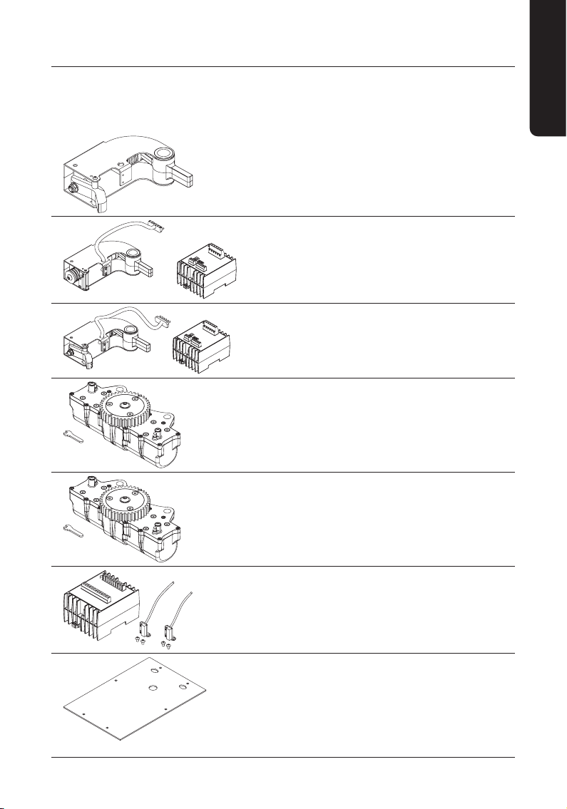
2. PACKAGE CONTENTS ........................................................................................................................ 4
3. OPTIONAL TURNITEC MODULES......................................................................................................... 5
4. PREPARING THE BASE MODULE ........................................................................................................ 6
5. INSTALLING OPTIONAL ACCESS CONTROL MODULES ............................................................................ 7
6. INSTALLING A CLOCKWISE MODULE................................................................................................... 8
7. INSTALLING AND CONNECTING AN ELECTRICAL CONTROL UNIT........................................................... 10
8. INSTALLING A COUNTERCLOCKWISE MODULE.................................................................................... 11
9. INSTALLING AND CONNECTING AN ELECTRICAL CONTROL UNIT........................................................... 13
10. INSTALLING AND CONNECTING A TT-COUNTER-LIGHT MODULE ON DINRAIL......................................... 13
11. INSTALLING A DAMPING MODULE ................................................................................................... 14
12. CLOSING THE BASE MECHANISM ..................................................................................................... 15
13. WELDING THE SPLINE AXIS............................................................................................................. 17
14. WELDING THE BASEPLATE................................................................................................................ 18
15. FIXATION & DRILLING PATTERN ....................................................................................................... 19
16. MOUNTING THE MECHANISM.......................................................................................................... 20
17. ELECTRICAL WIRING ...................................................................................................................... 21
18. MECHANICAL OVERRIDE OF THE CONTROL MODULES ...................................................................... 22
19. ADJUSTING DAMPING ACTION......................................................................................................... 22
20. SCREW THE COVER BACK IN PLACE.................................................................................................. 23

ENGLISH
4
Manual* - English
1. INTRODUCTION
Thank you for choosing our Locinox Turnitec mechanism. Please read the following instructions
thoroughly before installing the mechanism on your turnstile. Enclosed you will find all relevant user
information concerning the Turnitec & optional control modules.
2. PACKAGE CONTENTS
Please check if your package contains the following items:
*ALL DRAWINGS IN THIS MANUAL ARE APPLICABLE FOR BOTH THE TURNITEC 3 AND TURNITEC 4,
EXCEPT STATED OTHERWISE.
ACover EFixation bolts & nuts
BBase mechanism FElectrical coupling nuts
CCylinder keys GEyebolt
DSpline Axis
346 mm
13-5/8"
M20 x1,5 mm
M20 x3-15/16"
M16 x 1,5 mm
M16 x3-15/16"
DIN ISO 14
28 x 34 mm
1-1/8 x 1-5/16"
325 mm
12-13/16"
526 mm
20-11/16"
160 mm
6-5/16"
F
E
G
A
B
C
D

ENGLISH
5Turnitec (electro)mechanical control module
3. OPTIONAL TURNITEC MODULES
The Locinox (electro)mechanical control unit allows you to easily create a maintenance free and high
quality turnstile. You now have an (electro)mechanical unit at your disposal with which you can match
the design of your turnstile to the design of your gates!
TT-M34
Mechanical
module
TT-FO
Fail Open
electromodule
3-arm
TT-FC
Fail Close
electromodule
3-arm
TT-DM3
Hydraulic
damper for 120°
TT-DM4
Hydraulic
damper for 90°
TT-COUNTER-LIGHT
Turnitec counter &
passing lights module
TT-BSP
Welding plate in
black steel

ENGLISH
6
4. PREPARING THE BASE MODULE
•Screw the included coupling nuts in the base mechanism
6 x
•1 x M16x1,5 cap
•1 x M20x1,5 cap
•2 x M16x1,5 coupling nut
•2 x M20x1,5 coupling nut

ENGLISH
7Turnitec (electro)mechanical control module
5. INSTALLING OPTIONAL ACCESS CONTROL MODULES
•Loosen the cover with a screwdriver, and open it
10 mm
3/8"
X
X = Min. 115 mm (4-1/2”)
• Loosen the top chassis bolts, and remove them

ENGLISH
8
•Remove the spacing tubes: The base mechanism is now ready for optional modules
6. INSTALLING A CLOCKWISE MODULE
•If no clockwise module is needed, go to step 8 (Installing a counterclockwise module)
•Loosen the fixation bolt and slide the module over the axis
*ATTENTION - STEP B:
Installing the reed contact: only applies when a TT-COUNTER-LIGHT is needed. If you do not
install a TT-COUNTER-LIGHT module then please go to step C.
A B*C
TURNITEC 3 TURNITEC 4

ENGLISH
9Turnitec (electro)mechanical control module
• Make sure not to squeeze the cable (only with the electromechanical module)!
•Secure the clockwise module

ENGLISH
10
7. INSTALLING AND CONNECTING AN ELECTRICAL CONTROL UNIT
•Applies only for the TT-FO and TT-FC. If no electrical control unit is needed go to step 8: Installing a
counterclockwise module.
•Install the control unit on the dinrail.
• Connect the clockwise module with the control unit.

ENGLISH
11Turnitec (electro)mechanical control module
•Plug in the cable and make sure to tighten all six screws. Make sure the numbers on the control unit
correspond to the numbers on the connector.
8. INSTALLING A COUNTERCLOCKWISE MODULE
•If no counterclockwise module is needed, go to step 11: Installing the damper.
•Loosen the fixation bolt
•execute this step only if you need a TT-COUNTER-LIGHT module. If not then skip to the next step.

ENGLISH
12
•Slide the counterclockwise module over the axis.
•Tighten the fixation bolt of the counterclockwise module

ENGLISH
13Turnitec (electro)mechanical control module
9. INSTALLING AND CONNECTING AN ELECTRICAL CONTROL UNIT
•Applies only for the TT-FO and TT-FC. If no electrical control unit is needed go to step 11: Installing
the damper.
•Installation of the unit on DIN rail.
Connect the clockwise module with the electrical control unit & tighten the screws
A
A
AA
10. INSTALLING AND CONNECTING A TTCOUNTERLIGHT MODULE ON DINRAIL
*Electrical wiring: page 21

ENGLISH
14
11. INSTALLING A DAMPING MODULE
•If no damping module is needed, go to step 12 (Closing the base mechanism)
•Slide the damping module over both axes
•Pay attention to the position marks on the gear wheels
TURNITEC 3
TURNITEC 3
TURNITEC 4
TURNITEC 4

ENGLISH
15Turnitec (electro)mechanical control module
12. CLOSING THE BASE MECHANISM
•Make sure to put the spacing tubes back in place if no damping module is installed
TURNITEC 3
TURNITEC 4
•Damping module situations (No spacing tubes needed)

ENGLISH
16
•Check the concentricity between the bearing and the blocking disk (Due to spring tension, the
allignment of these 2 components can differ)
•Be sure the top chassis is mounted correctly before screwing it down.
10 mm
3/8"

ENGLISH
17Turnitec (electro)mechanical control module
13. WELDING THE SPLINE AXIS
•Alignment of the spline axis regarding the rotor
TURNITEC 3 TURNITEC 4

ENGLISH
18
•Length of the spline axis above the welding plate
X
X =Max. 140 mm (5-1/2”) and
Min. 65 mm (2-9/16”)
14. WELDING THE BASEPLATE
•If you choose not to use a Locinox welding baseplate (TT-BSP). Go to step 15

ENGLISH
19Turnitec (electro)mechanical control module
•The oval holes need to be directed to the passenger side.
•Align the base steel plate with respect to the rotor (Long side parallel to the rotor arm)
15. FIXATION & DRILLING PATTERN
•Prepare your own turnstyle baseplate for the Locinox Turnitec mechanism.
•Fixation and drilling pattern when not working with the TT-BSP.
TURNITEC 3 TURNITEC 4
97 mm
3-13/16"
130 mm
5-1/8"
152,5 mm
6"
152,5 mm
14-7/8"
355 mm
14"
75 mm
2-15/16"
87 mm
3-7/ 16"
84 mm
3-5/16"
84 mm
3-5/16"
87 mm
3-7/ 16"
25,4 mm ±0,1
1" ±0,0039"
37,8 mm ±0,1 mm
1-1/2" ±0,0039"
175 mm
6-7/8"
175 mm
6-7/8"
72,5 mm
2-7/8"
72,5 mm
2-7/8"
8,2 mm
6-1/16"
+ 0,2
154 mm
6-1/16"
154 mm
6-1/16"
Ø 36 mm
1-7/16"

ENGLISH
20
16. MOUNTING THE MECHANISM
•Slide the mechanism over the spline axis
•Attach the mechanism to the welding plate
A
A
This manual suits for next models
2
Table of contents
Languages:
Popular Turnstile manuals by other brands

Magnetic Autocontrol
Magnetic Autocontrol MPT-132 operating instructions

Tiso
Tiso ASTM F2656 M50 Installation and operation manual

HIK VISION
HIK VISION DS-K3G501S Series user manual

HIK VISION
HIK VISION DS-K3G501X Series manual

HIK VISION
HIK VISION DS-K3H4420-120 quick start guide

Oxgard
Oxgard CUBE ?-04 Series Installation guidelines