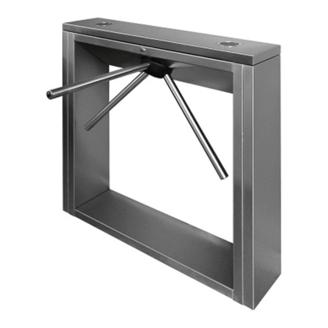
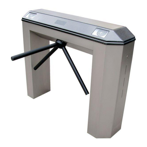
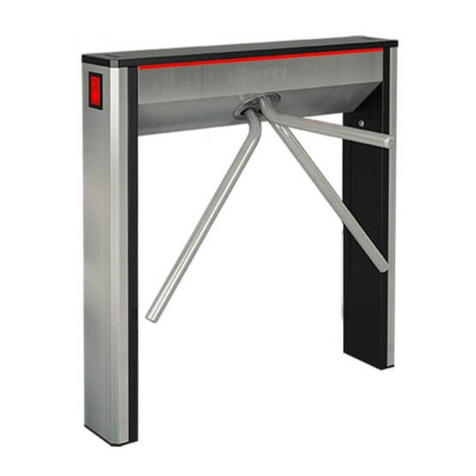
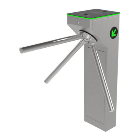
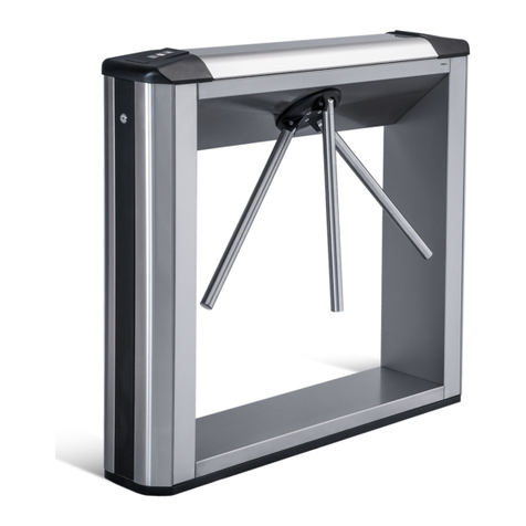
PERCo TTR-10A Series Installation and operating instructions

ASSEMBLY AND OPERATION MANUAL
TTR-10A
Electromechanical
tripod turnstile with automatic
antipanic arms

Electromechanical tripod
turnstile with automatic
anti-panic arms
TTR-10A
Assembly and Operation Manual

CONTENT
1APPLICATION......................................................................................................................... 3
2OPERATION CONDITIONS.................................................................................................... 3
3TECHNICAL SPECIFICATIONS ............................................................................................. 3
4DELIVERY SET....................................................................................................................... 4
4.1Standard delivery set..................................................................................................... 4
4.1.1Modification TTR-10AT.......................................................................................... 4
4.1.2Modification TTR-10AK ......................................................................................... 5
4.1.3Modification TTR-10AB ......................................................................................... 5
4.2Optional equipment supplied on request....................................................................... 6
5BRIEF DESCRIPTION............................................................................................................. 6
5.1Main features................................................................................................................. 6
5.2Design........................................................................................................................... 6
5.2.1Turnstile housing and base ................................................................................... 7
5.2.2LED indication unit................................................................................................. 7
5.2.3RC-panel ............................................................................................................... 8
5.2.4Control and interface boards................................................................................. 8
5.2.5Control signals..................................................................................................... 11
5.2.6Turnstile control modes....................................................................................... 12
5.2.7Turnstile mechanism operation algorithm............................................................ 12
5.3Operation devices ....................................................................................................... 13
5.3.1RC-panel connection........................................................................................... 13
5.3.2Emergency unblocking device Fire Alarm........................................................... 14
5.3.3Operation with an ACS controller........................................................................ 14
5.4Additional devices connectable to the turnstile ........................................................... 15
5.4.1Relay outputs....................................................................................................... 15
5.4.2Intrusion detector and siren................................................................................. 16
5.4.3Remote indicators................................................................................................ 16
5.5Operation contingencies and response....................................................................... 17
6MARKING AND PACKAGING............................................................................................... 17
7SAFETY REQUIREMENTS................................................................................................... 18
7.1Installation safety requirements................................................................................... 18
7.2Operation safety requirements.................................................................................... 18
8INSTALLATION INSTRUCTIONS......................................................................................... 18
8.1Installation details........................................................................................................ 18
8.2Installation tools........................................................................................................... 19
8.3Length of cables.......................................................................................................... 20
8.4Installation procedure.................................................................................................. 20
8.5Connection layout........................................................................................................ 24
9OPERATION INSTRUCTIONS.............................................................................................. 26
9.1Power-up..................................................................................................................... 26
9.2Operating modes of the turnstile at pulse control mode.............................................. 26
9.3Operating modes of the turnstile at potential control mode......................................... 27
9.4Actions in emergency.................................................................................................. 28
9.5Troubleshooting........................................................................................................... 28
10MAINTENANCE..................................................................................................................... 29
11TRANSPORTATION AND STORAGE .................................................................................. 30
Appendix 1. Control signal algorithm at pulse control mode.................................................. 30
Appendix 2. Control signal algorithm at potential control mode............................................. 31

TTR-10A electromechanical tripod turnstile
Dear Customer,
Thank you for purchasing the PERCo turnstile. Please follow the instructions given in the
Manual carefully, and this quality product will provide many years of trouble-free use.
Assembly and operation manual for the TTR-10A electromechanical tripod turnstile with
automatic anti-panic folding arms (hereinafter - the Manual) contains data necessary for the
utter use of the turnstile operating advantages. Packaging, installation and maintenance
information is as well provided.
Installation and maintenance are to be executed by qualified personnel only, after studying this
Manual carefully.
Abbreviations:
RC-panel – remote control panel;
ACS – access control system;
WRC – wireless remote control.
1 APPLICATION
TTR-10A electromechanical tripod turnstile with automatic anti-panic folding arms
(hereinafter - the turnstile) is a motorized, weatherproof blocking device, designed as a part of paid
access systems, including vehicles, as well as for managing the pedestrian flow at industrial
enterprises, banks, administrative institutions, shops, train stations, airports, etc. For a more
comfortable passage, the turnstile is equipped with an electric drive for smooth barrier arms
rotation and provides the ability to quickly open the passage area in case of emergency.
The turnstile is made in three modifications:
TTR-10AT with MT10.1 bracket for mounting on vertical cylindrical racks (pipes, handrails), for
example, in vehicles,
TTR-10AK with MT10.2 bracket for mounting on a vertical surface (wall),
TTR-10AB with MT10.3 mounting post for floor mount.
The number of turnstiles needed to ensure quick and convenient passageway is recommended to
be determined upon calculation of the turnstile throughput rate (Sect. 3). The manufacturer
recommends installing one turnstile according to the 500 people per shift criterion, or based on the
peak load of 30 people per minute.
24V DC output voltage power supply or rechargeable batteries are used to power the turnstile (for
the range of permissible voltages, see Section 3“Technical specifications”).
2 OPERATION CONDITIONS
The turnstile complies with GOST15150-69, category N1 (for an outdoor application) with regard to
environmental exposure resistance.
The turnstile operation is allowed at temperature range from -40°C to +50°C (up to +55°C under
the shelter) and at relative air humidity of up to 80% at +25°C.
The RC-panel, included in the standard delivery set, complies with GOST15150-69, category NF4
(operation in premises with climate control) with regard to environmental exposure resistance.
Operation of the RC-panel is allowed at temperature range from +1°C to +40°C and at relative air
humidity of up to 80% at +25°C.
3 TECHNICAL SPECIFICATIONS
Operating voltage ............................................................................................................ 22÷29V DC
Consumption current ......................................................................................................... max 5.5 A
Power consumption ......................................................................................................... 15÷150 W1
Turnstile throughput rate in the free passage mode ................................................. 60 persons/min
Turnstile throughput rate in the single passage mode .............................................. 30 persons/min
1Power consumption can reach 150 W only for a short time in certain turnstile conditions. The rest of the
time, power consumption does not exceed 15 W.
3

Assembly & Operation Manual
Passage width ....................................................................................................................... 500 mm
Arm rotation force ........................................................................................................... max 1.5 kgf
RC-panel cable length ............................................................................................................ 6.61m
Ingress Protection Rating ........................................................................................ IP54 (EN 60529)
Electric shock protection class ................................................................................... III (IEC 61140)
Vandal protection rating ......................................................................................... IK09 (IEC 62262)
Vibration resistance rating .................................................................... M28 and M29 (IEC 721-3-5)
Mean time to failure ................................................................................... min 3,000,000 passages
Mean lifetime .......................................................................................................................... 8 years
Turnstile overall dimensions with barrier arm raised (Fig. 1):
TTR-10AT modification with MT10.1 bracket assembled ............................. 613×806×746 mm
TTR-10AK modification with MT10.2 bracket assembled ............................. 613×806×714 mm
TTR-10AB modification with MT10.3 mounting post assembled ................ 1055×806×762 mm
Turnstile net weight:
TTR-10AT, TTR-10AK modification .......................................................................... max 33 kg
TTR-10AB with MT10.3 mounting post assembled ................................................... max 55 kg
Figure 1. Turnstile overall view
4 DELIVERY SET
4.1 Standard delivery set
4.1.1 TTR-10AT modification
Package:
Box .............................................................................................................................................. 1
Basic equipment:
Turnstile housing and base assembled ....................................................................................... 1
Hub with barrier arms .................................................................................................................. 1
RC-panel with cable .................................................................................................................... 1
Box with a MT10.1 mounting bracket (Fig. 14), includes:
Bracket base ............................................................................................................................... 1
Bracket back panel ...................................................................................................................... 1
Half-pipe clamps .......................................................................................................................... 2
M4×6 conical type screws ........................................................................................................... 4
M6×40 cylinder type screws ........................................................................................................ 8
1MAX allowed cable length – 40m (supplied on request).
4

TTR-10A electromechanical tripod turnstile
Installation tools:
M8×25 screws with spring washers for mounting the hub ........................................................... 3
Anaerobic adhesive sealant for fixing the hub screws (20 ml) .................................................... 1
SW3 Allen key ............................................................................................................................. 1
100 mm cable ties ....................................................................................................................... 5
M8 nuts ........................................................................................................................................ 4
Flat washers (8) ........................................................................................................................... 4
Spring washers (8) ...................................................................................................................... 4
Technical documentation:
Certificate .................................................................................................................................... 1
Assembly and operation manual ................................................................................................. 1
4.1.2 TTR-10AK modification
Package:
Box .............................................................................................................................................. 1
Basic equipment:
Turnstile housing and base assembled ....................................................................................... 1
Hub with barrier arms .................................................................................................................. 1
RC-panel with cable .................................................................................................................... 1
Box with a MT10.2 mounting bracket (Fig. 15), includes:
Assembled bracket ...................................................................................................................... 1
Installation tools:
M8×25 screws with spring washers for mounting the hub ............................................................3
Anaerobic adhesive sealant for fixing the hub screws (20 ml) .................................................... 1
SW3 Allen key ............................................................................................................................. 1
100 mm cable ties ....................................................................................................................... 5
M8 nuts ........................................................................................................................................ 4
Flat washers (8) ........................................................................................................................... 4
Spring washers (8) ...................................................................................................................... 4
Technical documentation:
Certificate .................................................................................................................................... 1
Assembly and operation manual ................................................................................................. 1
4.1.3 TTR-10AB modification
Package:
Box .............................................................................................................................................. 2
Box #1 includes:
Basic equipment:
Turnstile housing and base assembled ....................................................................................... 1
Hub with barrier arms .................................................................................................................. 1
RC-panel with cable .................................................................................................................... 1
Installation tools:
M8×25 screws with spring washers for mounting the hub ........................................................... 3
Anaerobic adhesive sealant for fixing the hub screws (20 ml) .................................................... 1
SW3 Allen key ............................................................................................................................. 1
100 mm cable ties ....................................................................................................................... 5
M8 nuts ........................................................................................................................................ 4
Flat washers (8) ........................................................................................................................... 4
Spring washers (8) ...................................................................................................................... 4
Technical documentation:
Certificate .................................................................................................................................... 1
Assembly and operation manual ................................................................................................. 1
Box #2 includes:
MT10.3 mounting post assembled for floor mount (Fig. 16) ............................................................ 1
5

Assembly & Operation Manual
4.2 Optional equipment supplied on request
Turnstile power supply...................................................................................................................... 1
WRC kit 1 .......................................................................................................................................... 1
Intrusion detector ............................................................................................................................. 1
Siren.................................................................................................................................................. 1
5 BRIEF DESCRIPTION
5.1 Main features
The turnstile is designed to work both indoors and outdoors or inside vehicles. The turnstile
housing is made of high quality stainless steel with polycarbonate insert.
The turnstile can operate independently or with control devices: the RC-panel, WRC or ACS.
The turnstile is equipped with automatic anti-panic folding arms. The barrier arm is set into
vertical position at a power loss or by emergency unblocking device Fire Alarm signal.
The turnstile is equipped with an operating mode indication. The turnstile provides an output
for connecting an additional external display as well.
The turnstile is equipped with relay inputs for an intrusion detector, a siren and the
emergency unblocking Fire Alarm device (i.e. fire protection system) connection.
The turnstile is equipped with an output for a power supply low voltage alarm connection.
There are two modes for the turnstile control - a pulse control mode and a potential control
mode.
The turnstile mechanism provides automatic barrier arm rotation to the initial position after
each pass.
After the barrier arms are turned 60° or more, the reverse rotation is blocked.
The rotor electric drive provides smooth and silent operation of the turnstile.
The turnstile is supplied with safe 24V voltage.
5.2 Design
The design of the turnstile (Fig. 2). Numbers in brackets correspond to Fig. 2and 3of this Manual.
The turnstile comprises turnstile base (6), housing (1) LED indication unit (2), hub (4) with three
barrier arms (3) and RC-panel. Additionally, depending on modification, the turnstile is equipped
with a mounting bracket for cylindrical racks (for example, in vehicles), for wall mounting, or
mounting post for installation on the floor. Optional equipment that is not included in the main
delivery set is supplied on request.
Figure 2. Turnstile components without a mounting bracket (post)
1 – turnstile housing; 2 – LED indication unit; 3 – barrier arm; 4 – hub;
5 – hub mounting screws; 6 – turnstile base; 7 – housing mounting screws
1The WRC kit consists of a receiver connected to the control board and transmitters.
6

TTR-10A electromechanical tripod turnstile
Figure 3. The internal turnstile components (with the housing and the hub removed)
8 – indication cable; 9 – control board; 10 – interface board;
11 – emergency unblocking device (Fire Alarm); 12 – assembled drive;
13 – grounding point; 14 – blocking device; 15 – hub mounting holes
5.2.1 Turnstile housing and base
You can access the internal components of the turnstile by detaching the housing (1). The housing
and the turnstile base are secured with four mounting screws (7) for SW3 Allen key. When
operating the turnstile, the housing must be secured to the base. Inside the base under the
housing are located (Fig. 3): the drive control board (9), interface board (10) and the turnstile
mechanism, which includes:
• drive (12) assembled with electric motor and position sensor board;
• electromechanical blocking device (14) with optical sensors;
• emergency unblocking device (Fire Alarm) (11) (anti-panic function of automatic folding arms).
5.2.2 LED indication unit
The housing (1) contains LED indication unit (2) to inform about the turnstile current status and the
established operation mode (Fig. 2and 4). The display has three pictographic indicators:
– passage permission indicator
in one of the directions (green arrow)
– passage denial indicator (red cross)
– passage permission indicator
in the other direction (green arrow)
Figure 4. LED indication unit
7

Assembly & Operation Manual
5.2.3 RC-panel
The RC-panel is designed as a small desktop device with a shockproof ABS plastic case and is
intended for setting and indicating operating modes when the turnstile is operated manually. The
RC-panel overall view (Fig. 5).
Figure 5. RC-panel design
1, 2, 3 – buttons LEFT, STOP, RIGHT for setting the control commands;
4, 6 – green indicators «Left», «Right»; 5 – red indicator «Stop»
There are three control buttons on the RC front panel intended for setting the turnstile operating
modes. The middle button on the RC-panel (hereinafter — the STOP button) is intended to set the
turnstile to the “Always locked” mode. The left (LEFT) and the right (RIGHT) buttons are intended
to unlock the turnstile for passage in the chosen direction. Above the buttons, there are LED
indicators for the turnstile turning mechanism. A red “Stop” indicator indicates that both passage
directions are blocked. Available control commands and indications on the RC-panel for pulse and
potential control modes are given in the Tables 5and 6. The RC-panel is connected to the
interface board in accordance with the connection layout (Sect. 5.3.1 and Fig. 17).
5.2.4 Control and interface boards
The control board (9) receives commands from the interface board (10) and controls the operation
of the electric motor, the operation of the blocking device, and the emergency unblocking device.
All nodes of the turnstile mechanism are connected to the control board with internal wiring. A
turnstile power source is connected to it with an external cable as well. Connection is made in
accordance with the connection layout (Fig. 17). The appearance of the control board (9) (Fig. 6).
Control board elements:
X1 (+24 GND)– turnstile power supply connector block;
X2 (POWER+CAN) – socket to connect communication cable with interface board;
X3 (Rotor Sensor) – the rotor position sensor board connector block (part of the drive (12));
X4 (A,B,C) – connector block for connecting the electric motor phases (part of the drive
(12));
X5 (Lock Sensor) – connector block for connecting the blocking device sensor optocouplers;
X6 (USB UDP) – USB port (not used during operation);
X7 (ANTIPANIC) – connector block to connect the electromagnet of automatic anti-panic
unblocking device (anti-panic function of automatic folding arms);
X8 (LOCK) – connector block to connect the blocking device electromagnet;
8

TTR-10A electromechanical tripod turnstile
XP1 – programming socket (not used during operation);
XP2 (USB UPD) – the jumper of the board software update via USB. If the jumper is fixed -
the update mode is ON, if removed – the update mode is OFF;
SA1 (CONTROL) – a set of DIP switches for setting the electric drive, must be in the OFF
position (not used during operation);
PWR – green LED indicator for interface board power supply.
Figure 6. Control board
The interface board (10) processes the incoming commands (monitors the status of contacts L, ST,
R and FA (Fire Alarm), reads information from the intrusion detector (DKZP1 contact) and
generates commands to the control board (9), as well as signals for external devices, for RC-panel
indications (Led A, Led ST and Led B), for the barrier arms rotation in the corresponding direction
(Pass A and Pass B), for the alarm output A1 – A2 (Alarm) and relays the signal about the current
status of the intrusion detector (DETECT).
The following devices are connected to the interface board: RC-panel / WRC / ACS controller,
emergency unblocking Fire Alarm device, remote display units and other optional equipment.
Wired connection is made in accordance with the connection layout (Fig. 17).
The general view of the interface board (10) (Fig. 7).
Figure 7. Interface board
Interface board elements:
X1 (ACS) – additional equipment power supply connector blocks (X1.1), siren connection
(X1.2) and ACS controller inputs for PASS signals (X1.3);
X2 (RC) – connector blocks for connecting the RC-panel, WRC or ACS controller (X2.1), as
well as emergency unblocking Fire Alarm device (X2.2);
X3 (Light) – connector blocks for connecting remote indicators (“open” / “closed”, X3.1 – for
direction A, X3.2 – for direction B);
9

Assembly & Operation Manual
X4-X6 (ADD) – connector blocks for connecting additional equipment (X4 - for intrusion
detector connection, X5 - Ready and Detect signal outputs; X6 - the alarm relay output for low
voltage (low battery);
X7 (CAN) – socket for interface board and communication cable interconnection (9);
X8 (INDICATION) – indication cable connection socket (8);
XP1 – programming socket (not used during operation);
XP2 (+12LED) – the jumper of board outputs relay operation indication. If the jumper is fixed -
indication is ON, if removed – indication is OFF;
SA1 (SETUP) – a set of DIP switches:
1 – turnstile control mode selection: ON - pulse (set by default), OFF - potential,
2 – barrier arms turn force value selection:
ON – hard (used when operating the turnstile in vehicles, in order to compensate for
possible barrier arms shaking and vibration when the vehicle is moving),
OFF – soft (used when operating the turnstile on fixed surfaces, in rooms, offices, etc.),
set by default.
3,4 –not used during operation, must be in the OFF position.
PWR – green LED indicator for interface board power supply.
Table 1. Pin assignment of connector blocks
№Legend Assignment
Control board connector blocks
X1 (POWER)
1 +24
2 GND Turnstile power supply 24V DC, 9A
Interface board connector blocks
X1(ACS)
1 +12OUT
2 GND +12V power supply for additional equipment (siren)
3 A1
4 A2 «Alarm» relay output (siren connection)
5 C Common for PASS relay outputs
6 Pass A PASS A relay output (passage in A direction)
7 Pass B PASS B relay output (passage in B direction)
X2 (RC)
1 GND General
2 L Control input - passage A permission
3 ST Control input - passage denial
4 R Control input - passage B permission
5 Led A Passage A permission indication output on the RC-panel
6 Led ST Passage denial indication output on the RC-panel
7 Led B Passage B permission indication output on the RC-panel
8 Sound RC-panel sound signal output
9 FA
10 GND Emergency passage unblocking control input
X3 (LIGHT)
1 NO1 Normally open contact of the external Light A output
2 C1 Common contact of the external Light A output
3 NC1 Normally closed contact of the external Light A output
10

TTR-10A electromechanical tripod turnstile
№Legend Assignment
4 NO2 Normally open contact of the external Light B output
5 C2 Common contact of the external Light B output
6 NC2 Normally closed contact of the external Light B output
Remote connector blocks X4-X6 (ADD)
1 +12OUT +12V output for additional equipment powering (intrusion detector)
2 DKZP1
3 DKZP2
4 GND Intrusion detector connection
5 COM Common for DETECT and READY
6 DETECT Det Out relay output (intrusion detector status)
7 READY Ready relay output (turnstile readiness)
8 LV1
9 LV2 The alarm relay output for low voltage (low battery)
5.2.5 Control signals
Turnstile operation is performed by sending a control signal to L, ST and R X2 connector block
contacts on the interface board. The control signal is a low-level signal regarding the GND contact.
Normally open relay contact or scheme with an open collector output can serve as a control
element (Fig. 8and 9).
Turnstile emergency unblocking is performed by a low-level signal release from FA connector of
the X2 connector block on the interface board regarding the GND contract. A normally closed relay
contact or a scheme with an open collector output can serve as a control element. In this case all
other incoming control commands are ignored. (Sect. 5.3.2)
Sending a low-level signal to Fire Alarm input, you put the turnstile directions into the mode
according to the signal levels at the inputs L, R, and ST.
Intrusion detector activation is monitored by a low-level signal release from the DKZP1 input on the
interface board regarding the GND contact. A normally closed relay contact or a circuit with an
open collector output can serve as a control element.
Note:
Use resistors with 1 kOhm strength, connected to +3.3V power line to generate a high-level
signal on all input contacts (L, ST, R, FA and DKZP).
Control element is to provide the following characteristics of the signals:
control element – relay contact:
minimum switched current ...................................................................................... max 2mA
closed contact strength (with regards to connecting cable strength)................ max 300 Ohm
control element – scheme with an open collector output:
closed contact voltage (low-level signal, on the control board input)...................... max 0.8V
Figure 8. ACS control elements – normally open relay contact
11

Assembly & Operation Manual
Figure 9. ACS control elements – scheme with an open collector output
5.2.6 Turnstile control modes
There are two turnstile control modes – pulse and potential. In both modes the turnstile is
controlled by sending commands (i.e. control signals combinations) to L, ST and Rcontrol inputs
and to a special FA control input. Control command sending algorithm changes depending on the
chosen mode (Tables 5and 6).
The control mode is set either ON or OFF by SA1 (SETUP) switcher on the interface board (10).
Switcher location (Fig. 7). Shift the switcher into ON position to switch the turnstile into pulse mode.
Shift the switcher into OFF position to switch the turnstile into potential control mode.
Caution!
Shift the switcher with de-energized equipment only.
Pulse control mode is used for turnstile operation from RC-panel, WRC and ACS controller with
the outputs supporting pulse control mode.
Control signal duration at sending control command to control inputs is to be not less than 100ms.
The initial passage waiting time is 8 sec., it is independent of control signal (pulse) duration.
The turnstile operation description for this mode is given in Table 5. Control command sending
algorithm is given in Appendix 1.
Potential control mode is used for turnstile operation with ACS controller. The outputs of the ACS
controller are to support potential control mode.
Control signal duration at sending control command to control inputs is 100ms. minimum. The
passage waiting time is equal to low-level signal duration, i.e. if by the moment of passage
completion in the permitted direction, there’s a low-level signal on the input of this direction, the
turnstile remains open in this direction.
The turnstile operation description for this mode is given in Table 6. Control command sending
algorithm is given in Appendix 2.
By sending a low-level signal to ST input, both directions are locked in accordance to signal
duration time, independently of signal levels on L and R inputs. Removing low-level signal from ST
input, the directions shift into the modes, according to signal levels on L and R inputs.
The turnstile operation at the FA control input is described in Sect. 5.3.2.
5.2.7 Turnstile mechanism operation algorithm
Turnstile operation algorithm at pulse control mode in case of single passage in one of the
directions:
1. Turnstile starting position - the drive is turned off, passage denial indicator is on, when you try
to turn the barrier arms more than 5° in any direction, the blocking device blocks the hub, an
alarm is turned on - passage through the turnstile is closed.
2. The command (combination of control signals) for single passage performance in one of the
directions is sent from the control device (RC-panel, WRC, ACS controller) to the interface
board inputs.
12

TTR-10A electromechanical tripod turnstile
3. The microcontroller on the control board (9) processes the received combination of signals and
creates a command for the turnstile mechanism to open the passage in the desired direction
(blocking device opens).
4. The microcontroller monitors the barrier arms hub rotation sensor status, and counts the
elapsed time since the button on the RC-panel, that corresponds to the passage permission in
the desired direction, was pressed.
5. When the user turns the barrier arms 10° in the authorized direction, the microcontroller sends
a signal to the drive to smoothly rotate the hub in the passage direction to the next starting
position, thereby providing a comfortable passage in a given direction. When turning the barrier
arms 60°, a PASS A (B) signal with a duration of 250ms. is generated (PASS A (B) and
Common contacts open).
6. After turning the barrier arms 60°, the possibility of reverse rotation is blocked by both the
electric drive and blocking device - it is now possible to move forward to the next starting
position only.
7. In case of passage denial, i.e. if after 8 seconds from the moment of passage permission the
barrier arms were not rotated 60° or more, the microcontroller generates a command to the
control mechanism to block the further passage in this direction, while the drive will return the
barrier arms back to original position.
8. When the barrier arms reach the initial position (120° rotation of the barrier arms or if the
passage is denied by 0°), the microcontroller enters the standby mode.
In the “Free passage ...” operating modes, the algorithm remains the same, except the turnstile is
not blocked at the end of the passage, but expects a new passage.
5.3 Operation devices
RC-panel / WRC or ACS controller can be used for turnstile operation. These devices can be
connected to the turnstile separately, simultaneously (in parallel) or in any combination with each
other.
Note:
In case several control devices are connected to the turnstile simultaneously there can be a
control signal overlap. In this case the turnstile reaction will correspond to the reaction to
the resulting input signal combination (Appendixes 1 and 2).
5.3.1 RC-panel connection
RC-panel is connected to GND, L, ST, R, Led A, Led ST and Led B contacts of the X2.1 connector
block (Fig. 17).
Standard RC-panel orientation regarding the turnstile post is stated in Fig. 10.
Figure 10. Standard RC-panel orientation regarding the turnstile post
If the operator is located on the opposite side regarding the turnstile post, it will be more
convenient to shift the RC-panel wires, which are connected to L and R contacts, as well as Led A
and Led B (Table 2).
13

Assembly & Operation Manual
Table 2. Connection of RC-panel cable wires to the X2.1 connector block
for standard and reverse RC-panel orientation
RC-panel orientation
№Contact Standard Reverse
1 GND black black
2 L white green
3 ST blue blue
4 R green white
5 Led A yellow red
6 Led Stop orange orange
7 Led B red yellow
8 Sound brown brown
Note:
WRC is connected to L, ST, R and GND contacts of the X2.1 connector block on the
interface board. WRC power supply can be connected to +12OUT contact of the X4
connector block or X1.1 connector block.
When the RC-panel buttons are pressed, the corresponding contact L, ST and Rcloses with the
GND contact (i.e., a low-level signal formation relative to the GND contact).
Turnstile control using the WRC device is similar to that with RC-panel.
The buttons on the WRC tag act the same way as those on the RC-panel.
The WRC operation manual is supplied with the device.
5.3.2 Emergency unblocking device Fire Alarm
The emergency unblocking device is connected to the contacts FA and GND of the X2.1 connector
block on the interface board in accordance with the connection layout of the turnstile (Fig. 7and 17).
If the Fire Alarm is not used, it is necessary to set a wire jumper between the FA and GND
contacts. The jumper is installed upon delivery.
When a control signal is sent to the FA input, the turnstile switches to the Fire Alarm emergency
free passage mode with all the incoming turnstile control commands ignored. The central barrier
arm automatically falls down under its own weight and takes up a vertical position, ensuring free
passage. Both green direction arrows will flash, briefly changing to a red cross on the turnstile LED
indication unit (2).
If the Fire Alarm signal is received while making a passage, the Fire Alarm flashing will be
activated on the LED indication, but the emergency unblocking function will be activated only after
the rotation is finished.
After the Fire Alarm control signal has been removed, the red passage denial indicator on the
turnstile LED indication lights up, and the turnstile goes into standby mode. To continue working,
the barrier arm must be manually fixed and set to the horizontal position.
Automatic anti-panic function is also activated at a power supply loss, e.g. in case of connected
power supply unit breakdown.
5.3.3 Operation with an ACS controller
The turnstile can be an operating device as part of an ACS. The ACS controller outputs are connected
to the GND, L, ST, R contacts of the X2.1 connector block on the interface board. ACS controller inputs
are connected to the contacts C (Common), Pass A, Pass B of the X1.3 remote connector block.
Connection is made in accordance with the connection layout of the turnstile (see Fig. 17).
If necessary, the controller inputs can be connected to the READY, DETECT and COM X5
connector block contacts to monitor the corresponding turnstile conditions.
14

TTR-10A electromechanical tripod turnstile
In the pulse control mode control over the turnstile with an ACS controller is similar to that with the
RC-panel.
For organizing single passes in the potential control mode, it is recommended to remove the low-
level control signal upon passage through the turnstile, i.e. at the beginning of the corresponding
direction PASS signal.
5.4 Additional devices connectable to the turnstile
5.4.1 Relay outputs
Connection to the control board relay outputs is performed through the corresponding contacts of
the X1 and X5 connector blocks on the interface board. The following relay outputs are installed:
«Alarm»:contacts A1 and A2 (Sect. 5.4.2);
«PASS
A»:contacts Pass A and C(Sect. 5.2.7);
«PASS
B»:contacts Pass B and C(Sect. 5.2.7);
«Not
ready»:contact READY and COM (Sect. 5.5);
«Detector»:contacts DETECT and COM(Sect. 5.4.2);
«Battery»:
contacts LV1 and LV2 (Sect. 5.5).
Relays “PASS A” (Pass A and Ccontacts), “PASS B” (Pass B and Ccontacts), “Detector” and “Not
ready” (DETECT, READY and COM contacts) have normally open contacts when the power is off.
Moreover, the C and COM contacts common to these relays are not connected to the turnstile
power supply minus.
Relays “Alarm” (contacts A1 and A2) and “Battery” (LV1 and LV2) have normally open contacts
when the power is off.
In the initial (inactive) state when the power is on, the “PASS A” and “PASS B” relay contacts are
closed (voltage is applied to the relay coil), and the “Detector”, “Not ready”, “Alarm” and “Battery”
relay contacts are open (voltage to relay coil is not applied).
The actuation / release of the “PASS A”, “PASS B”, “Ready”, “Detector”, “Alarm” and “Battery”
relays can be determined by the light-on / off of the green indicators installed near the indicated
relays (Fig. 7) (indicators work with the XP2 jumper installed).
Figure 11. Pass elements PASS A, PASS B, Ready, Det Out and Alarm
15

Assembly & Operation Manual
Pass elements for “PASS A”, “PASS B”, “Ready”, “Detector” - relay contacts (Fig. 11) with the
following signal characteristics:
maximum commutation DC voltage ....................................................................................... 42V
maximum commutation current............................................................................................ 0.25A
closed contact resistance....................................................................................... max 0.15 Ohm
Pass elements for «Alarm» and «Battery» – relay contacts (Fig. 11) with the following characteristics:
maximum commutation DC voltage ........................................................................................ 30V
maximum commutation AC voltage ........................................................................................ 42V
maximum commutation AC/DC current ....................................................................................... 3
closed contact resistance....................................................................................... max 0.15 Ohm
5.4.2 Intrusion detector and siren
Caution!
Installation of the intrusion detector is made in accordance with the passage area layout and
climatic resistance of the detector. No intrusion detector installation inside the turnstile post
is possible.
The intrusion detector is connected to the X4 connector block contacts, and the siren is connected
to the X1 connector block on the interface board (10) according to the connection layout (Fig. 7
and 17). There should be normally closed contacts on the intrusion detector. In case the intrusion
detector is not connected, it is necessary to set a wire jumper between the contacts DKZP1 and
GND of the X4 connector block. The jumper is installed upon delivery.
The siren is connected to the Alarm 1, Alarm 2 and GND contacts and +12V of the XT1.H connector
block. The parameters of the alarm relay output signals “Alarm” are indicated in Sect. 5.4.1.
If the turnstile is locked (the command “Always Locked” or “Both passage directions are locked” is
given, Tables 5and 6) the DKZP1input is activated and a signal comes from the intrusion
detector, the “Alarm” output is activated. The "Alarm" output is disabled 5 sec. after activation or by
executing of any received command. The signal from the intrusion detector is ignored for the period
of authorized unblocking of the turnstile in either or both directions.
Note:
The control signal from the intrusion detector does not activate the ALARM output if the
turnstile turning mechanism is unlocked in one of the directions or was blocked less than
3 sec. ago.
A signal about the intrusion detector current state is always transmitted to the DETECT contacts
(relay "Detector") and COM of the X5 connector block on the interface board (Fig. 7).
The parameters of the “Detector” relay output signals are indicated in Sect. 5.4.1.
5.4.3 Remote indicators
Remote indicators for corresponding passage directions are connected to X3 (LIGHT) connector
blocks - NO1, C1, NC1, NO2, C2, NC2. The relay “Light A” (“Light B”) is activated (voltage is
supplied to its winding) when the green arrow corresponding to this direction of passage is lit on
the LED indication unit, and normalized (voltage is not supplied to its winding) when it is not lit. The
fact of “Light A” and “Light B” relays operation can be determined by the state of the indicators that
are installed near the indicated relays (Fig. 7) (this indication works when the XP2 (+12LED)
jumper is installed).
Pass elements for “Light A” and “Light B” - relay transfer contacts (Fig. 12) with the following signal
characteristics:
maximum commutation DC voltage ....................................................................................... 30V
maximum commutation AC voltage......................................................................................... 42V
maximum commutation AC/DC current..................................................................................... 3A
closed contact resistance....................................................................................... max 0.15 Ohm
16

TTR-10A electromechanical tripod turnstile
Figure 12. Light A and Light B pass elements
5.5 Operation contingencies and response
The turnstile is capable of providing information on the following operation contingencies:
1. Unauthorized access.
2. Passage delay for more than 10 sec.
3. Barrier arms rotation sensor failure.
4. Intrusion detector activation (Sect. 5.4.2).
5. Power failure (decrease below acceptable level)
In the cases 1-4, a special Alarm signal is generated by closing the A1 and A2 X1 connector
contacts. The "Alarm" relay output signals parameters are indicated in Sect. 5.4.1.
When eliminating the cause of the Alarm signal, the "Alarm" relay contacts open and the signal is
removed.
An alarm lamp (buzzer) in the driver's cab can be connected to the output of the “Alarm” relay,
alerting the turnstile emergency operation.
During operation, the microprocessor monitors the voltage supplied to the turnstile, and when the
voltage is reduced (less than 21.8V), the "Battery" relay contacts (LV1 and LV2 of X6 connector
block on the interface board (10)) will be closed to each other, indicating a low supply voltage (low
battery). With a subsequent increase in voltage to 23.6V, the "Battery" relay contacts LV1 and LV2
will open, thus indicating a nominal supply voltage (battery charge). The parameters of the
“Battery” relay output signals are indicated in Sect. 5.4.1.
In case of a voltage drop below the threshold value for switching off the electronics (17V), the
turnstile electronics will automatically disconnect from the power source. When voltage is restored
above the threshold for switching the electronics on (18V), the turnstile electronics will
automatically turn on.
6 MARKING AND PACKAGING
The turnstile has the marking on the inner surface of the side wall of the turnstile base. The label
contains manufacturer’s trademark and contact details, year and month of production, operating
voltage and power consumption of the turnstile.
To get access to the label it is necessary to detach the turnstile housing (1) from the turnstile base
in the following way:
1. Unscrew the four fixing screws of the housing (7) using the SW3 Allen key. The screws are
located on the lower surface of the turnstile base, the hub side.
2. Lift the turnstile housing by the lateral faces to half the height of the turnstile base.
3. Separate the indication cable (8) from LED indication unit (2).
4. Detach the housing carefully and put it on a plain and steady surface.
The housing is mounted on the turnstile base in the reverse order. When lowering the housing,
make sure that the indicator cable (8) folds forward and is not pinched by structural elements.
The complete delivery set of the turnstile (Sect. 4.1) is packed in a transportation box, which keeps
it undamaged during the transportation and storage:
17

Assembly & Operation Manual
Modification TTR-10AT, TTR-10AK, 1 box in each:
Transportation box dimensions (L×H×W) ................................................................... 104×40×32cm
Transportation box weight (gross) ..................................................................................... max 58kg
Modification TTR-10AB, 2 boxes:
Transportation box #1 dimensions (L×H×W) .............................................................. 104×40×32cm
Transportation box #1 weight (gross) ................................................................................ max 53kg
Transportation box #2 dimensions (L×H×W) .............................................................. 115×40×22cm
Transportation box #2 weight (gross) ................................................................................ max 33kg
7 SAFETY REQUIREMENTS
7.1 Installation safety requirements
The turnstile installation must be carried out by specialists who have fully studied this manual and
passed safety training, in accordance with the general rules for the implementation of electrical and
installation work.
Warning!
The power source or battery must be turned off and unplugged during installation of the
turnstile.
Only serviceable tools must be used for installation.
Lay the cables in compliance with the electrical installations rules of operation.
Before turning on the turnstile for the first time, make sure it's installed and connected
correctly.
Power supply unit installation must be made in accordance with the safety rules given in its
certificate.
7.2 Operation safety requirements
Follow general electrical safety rules when operating the turnstile.
It is prohibited!
Do not use the turnstile under conditions that do not comply with the requirements of
Section 2of this Manual.
Do not use the turnstile at supply voltage that does not comply with the requirements of
Section 3of the Manual.
The power supply unit should be used in compliance with its operational documentation.
8 INSTALLATION INSTRUCTIONS
Follow the safety requirements during the installation (Sect. 7.1).
Warning!
The manufacturer is not responsible for any damage to the turnstile or other equipment, as
well as other damages caused by improper installation, and rejects any consumer
complaints if the installation is performed in violation of the instructions given in this
manual.
8.1 Installation details
The turnstile installation is a demanding operation, both performance and service life of the product
largely depend on it. Installation must be carried out by at least two specialists qualified as an
installer and an electrician. It is recommended to study this section carefully prior to installation,
and follow the given instructions.
Installation surface recommendations:
The turnstile can be mounted on the cylindrical racks (vertical pipes) of the vehicle using the
MT10.1 bracket (for TTR-10AT modification), or on a strong vertical wall with the MT10.2 bracket
(for TTR-10AK modification), or on a concrete floor using the MT10.3 mounting post (for
TTR-10AB modification).
18

TTR-10A electromechanical tripod turnstile
The MT10.1 bracket must be installed on vertical (level-controlled) steel pipes with a diameter of
30-35 mm, and at least 2 mm of thickness, securely fixed to the floor (floor and ceiling) using
flanges with a support area of at least 75 cm2each (mount flanges with three or four M8 bolts at
least). The distance between the uprights at the bracket mounting location should be 263±1 mm.
MT10.2 mounting bracket should only be installed on the main walls of concrete buildings (grade
400 or higher) with at least 10 mm thickness, using at least four M8 or M12 anchor bolts. In this
case, the bracket mounting points must resume in one vertical plane (control with a level).
Warning!
The turnstile installation height must be taken into account, when installing it on the
brackets. The recommended turnstile installation height should be approximately
900-950 mm from the floor to the upper edge of the barrier arm.
The MT10.3 mounting post must be installed on strong, even, stone or concrete (grade 400 or
higher) or other bases with a thickness of at least 150 mm, using four M12 anchor bolts. In this
case, the installation surface must be leveled the way the mounting points of the turnstile post are
in the same horizontal plane (control with a level). When installing the turnstile post on a less solid
base, it is necessary to use embedded foundation elements of at least 300×300×300 mm size. It is
also possible to use a frame base.
Passage zone organization:
The turnstile is equipped with an electric drive for the barrier arms rotation. When rotated 5° or
more, the barrier arms turn in the passage direction (when rotated 60° or more, the barrier arms
cannot be returned to their original position, since the return passage is blocked). When rotated at
an angle of less than 60° the barrier arms return to their original position in 8 sec. To ensure
accurate tracking, when the turnstile is operated from an ACS, it is recommended to create the
passage area in such a way that the barrier arms should turn in the passage direction by an angle
of more than 60° (Fig. 13).
Follow the recommendations (Fig. 13) to ensure the required angle of rotation when installing the
turnstile.
When organizing the passage area, it is recommended to arrange an additional emergency exit.
For example, it can be the BH-02 automatic rotary section (Sec. 9.4).
Figure 13. Passage area. Recommendations
8.2 Installation tools
Tools recommended for the turnstile installation:
1.2÷1.5kW hammer drill;
Ø16 mm hard-alloyed drill bits;
Floor chaser for electric raceway;
Flat slot SL3×0.5 screwdriver;
19
This manual suits for next models
3
Table of contents
Other PERCo Turnstile manuals

PERCo
PERCo TTR-07.1 Installation and operating instructions

PERCo
PERCo RTD-15 Series User manual

PERCo
PERCo TTR-08A Installation and operating instructions

PERCo
PERCo ST-02 Series User manual

PERCo
PERCo RTD-03S User manual

PERCo
PERCo TTR-04CW-24 Installation and operating instructions

PERCo
PERCo Turnichetul TB 1 Supplement

PERCo
PERCo TTD-03.2 User manual

PERCo
PERCo RTD-20 User manual

PERCo
PERCo TTR-04CW Installation and operating instructions