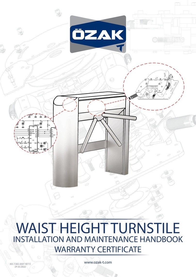
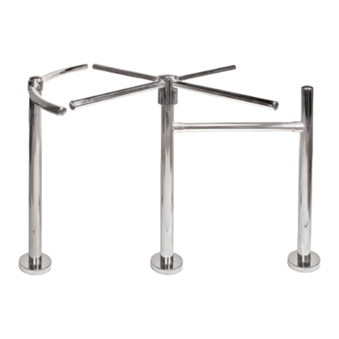
Timewatch TWLD-TS2700 User manual

(+91)-11–41916615
+91 9609749609
www.TimeWatchindia.com
Matters Needing Attention
The internal wiring of this product has been completed when leaving the factory. Please do not
change any wiring except what has been done in this manual Instructions. The company is not
responsible for any damage caused by unexplained alterations.
The casing must be grounded, and installed in the power supply end leakage protection switch.
It is strictly forbidden to open the door and lid of the box when the pedestrian gate is working, so
as to avoid accidental personal accidents.
D-162, Okhla Phase-I, Okhla Industrial Area,
New Delhi,110020

1. Introduction of channel gate products
2. Functional features of the channel gate
3. Technical parameters of the channel gate
4. Installation and debugging details
5. Composition and principle of channel gate equipment
5.1 Composition of channel gate products
5.2 System working principle
6. Installation and debugging of channel gate equipment
6.1 Installation of channel gate equipment
6.2 Functional debugging of channel gate equipment
7. Troubleshoot common faults
8. Appendix: Three-roll brake protocol communication
(+91)-11–41916615
+91 9609749609
www.TimeWatchindia.com
Directory
D-162, Okhla Phase-I, Okhla Industrial Area,
New Delhi,110020

Channel gate is the intelligent channel management equipment developed and produced by our
company for many years. The device integrates mechanical, electronic, microprocessor control, and
various reading and writing technologies. The appearance of the equipment adopts stainless steel
plate laser welding molding, beautiful appearance, rust-proof, durable, and external use of standard
electrical interface, can easily bar code card, ID card, IC card, and other card readers integrated into
the equipment, to provide a civilized, orderly way of passage for people in and out, but also put an
end to illegal personnel in and out; In addition, the system also specially designed to meet the fire
protection requirements of the function, in the event of an emergency, to ensure that the passage is
unimpeded, convenient personnel timely evacuation;
(+91)-11–41916615
+91 9609749609
www.TimeWatchindia.com
1. Introduction of channel gate products
1) Free passage, swipe card passage, and other ways of passage; 2) Anti-shock function, in the
absence of receiving the opening signal, the rotating rod is locked; 3) Automatic reset function with a
timeout. If the pedestrian does not pass through the system within the specified time after reading the
valid card, the system will automatically cancel the pedestrian's permission to pass and turn the lever
to lock;4) Unified standard external electrical interfaces, can be connected with a variety of card
readers, and can achieve remote control and management through the management computer;
2. Functional features of channel gate
3. Technical parameters of channel gate
The body material 304 stainless steel The input power AC220 plus or minus
10% V, 50 hz;
Working voltage 24V DC Relative humidity Relative humidity ≤ 90%,
no condensation
Working
temperature
-30 ℃ -70 ℃Traffic speed 25-35 people per
minute
Open the signal Relay dry contact
signal
Use place Indoor/Outdoor
D-162, Okhla Phase-I, Okhla Industrial Area,
New Delhi,110020

(+91)-11–41916615
+91 9609749609
www.TimeWatchindia.com
4. Installation and debugging details
The hole reserved for connecting line is shown in the figure, which can be knocked off for wiring
When the power is connected, press the pole in the direction of the arrow first. When you hear the
sound of "da", it means that the magnet has been drawn and you can lift the pole.
D-162, Okhla Phase-I, Okhla Industrial Area,
New Delhi,110020

(+91)-11–41916615
+91 9609749609
www.TimeWatchindia.com
The machine structure
5. Composition and principle of channel gate equipment
5.1 composition of channel gate products
5.1.1 Channel gate mechanical system
Channel gate mechanical system is divided into chassis and movement of two parts. The chassis
as a carrier, installed on the direction indicator light, read and write device, etc. The main
components of the movement are the frame, drive shaft, rotating rod, and limit piece;
5.1.2 Electronic control system of channel gate
Electronic control system is composed of card reader, main control board, limitinduction switch,
direction indicator light, transformer, etc. Card reader: after reading the information on the card and
judging the processing,send a signal to the main control board to apply for passage (switch signal)
◆
Main control board: the control center of the system, it receives the signal ofthe card reader and
limit induction switch, and makes logical judgment and processingof these signals, and then issues
execution commands to the direction indicator lightand alarm
◆
Direction indicator light: shows the current passage sign status, and guidepedestrians to pass
safely and orderly
D-162, Okhla Phase-I, Okhla Industrial Area,
New Delhi,110020

(+91)-11–41916615
+91 9609749609
www.TimeWatchindia.com
S.No. The name of the function
Entrance guard
system
Control panel
Direction
indicator light
Limit switch
IC/ID card access control, fingerprint machine,
face recognition, TWO-DIMENSIONAL code
equipment
The control center of the system, it receives
the signal of card reader and infrared sensor,
and makes logical judgment and processing to
these signals, and then sends the execution
command to the direction indicator
Display the current traffic status of the channel
to guide pedestrians through the channel
Open and close the brake in place detection
Switching power
supply Control panel power supply
1
2
3
4
5
5.2. System working principle
◆
Turn on the power, 3 seconds after the system is into the working state
◆
When the card reader reads the effective card, the direction indicator light changes color,
indicating the success of reading the card, but also judges and processes the information read
from the card and sends a traffic authorization signal to the main control board
◆
The main control board receives the card reader and limit switch signal, and after
comprehensive processing, to the direction indicator light and solenoid valve, send an effective
control signal, so that the direction indicator light changes color, the main control board control
solenoid valve to unlock, allow pedestrians
◆
If pedestrians forget to read cards or read invalid cards into the channel, the system will prohibit
pedestrians, read valid card authorization before allowing passage. The alarm will not be lifted until
the pedestrian exits the channel; Reread validate-square cleared for passage.
D-162, Okhla Phase-I, Okhla Industrial Area,
New Delhi,110020

(+91)-11–41916615
+91 9609749609
www.TimeWatchindia.com
6. Installation and debugging of channel gate equipment
6.1. Installation of channel gate equipment
◆
Prepare tools for installing devices and check accessories according to the packing list.
◆
After completing the foundation surface of the installation equipment, arrange the equipment
and make sure that the equipment is aligned horizontally.
◆
After locating the holes, drill the holes, and rebury the anchor bolts or expansion bolts of M12.
◆
Open a routing groove, put the strong electric cable through with a 3/4 "PVC pipe, and bury it in
the corresponding position with cement.
◆
Put the device back to the installation position and secure the brake with the factory-configured
layering and expansion bolts.
◆
Refer to the wiring diagram, connect the power cable, and connect the system grounding cable
protection.
◆
The following functions can be debugged only when the device status is normal. Check the
mains wiring according to the wiring diagram, check that the power supply wiring and other
wiring of the whole equipment are correct, and power on the adjustment after confirmation Try.
Expansion Screw Cement 525
M12
Foot Installation Basic Diagram
Base mounting dimension
D-162, Okhla Phase-I, Okhla Industrial Area,
New Delhi,110020

(+91)-11–41916615
+91 9609749609
www.TimeWatchindia.com
6.2. Functional debugging of channel gate equipment
(Note: The gate machine of our company has been adjusted normally in the workshop according to
the order requirements before leaving the factory. Now it is installed according to the requirements
without debugging. For fine-tuning, please refer to the following parameter description and contact
after-sales guidance.)
6.2.1 Key Description
Control panel keys:
ENT menu key, INC up/add key, DEC down/subtract key
ENT key: used to enter the menu item setting items or current parameter modification
confirm save
ESC key: used to return to the upper menu and exit the menu
6.2.2 Wake up from the Menu
Step 1: Press "ENT" for 3 seconds to enter the system menu, and use "INC" and"DEC" to scroll up
and down respectively to select the "F 0 1" menu(see below for menu description).
Step 2: Press ENT to enter the interface for setting the channel duration.
Step 3: Use the "INC" and "DEC" keys to add or subtract parameter values, respectively.
Step 4: Press "ENT" to save the settings.
Step 5: Exit menu: Press the ESC key to exit the menu
F 0 1 Set the traffic duration; Within this set period, if no one passes, the gate will automatically
close. (5 seconds by default)
F 0 2 Allow and prohibit passage; Gate traffic mode.0: left free passage, right swipe card
pass.1: left swipe card access, right free access.2: All free passage. 3: all card access
(default).
F 0 3 Brake working mode; 0: full-height switch mode 1: three-roll switch mode (default three-
roll switchmode)
F 0 4 (Continuous swipe function) Memory function, open or close the entrance to pass
whether there is a memory function, generally used for card opening, in the case of a person,
who has not passed the card, whether to remember other people's card."00 Prohibited" means
that the second person can swipe the card only after the first person passes; "01 allow" is how
many people swipe card, namely, allow continuous access to how many people. (Default: 00)
F 0 5 Repeated opening and the closing test are mainly used to test the stability and aging of
the gate control board. Note: In test mode, press ESC to exit the test
6.2.3 Setting Function Parameters
D-162, Okhla Phase-I, Okhla Industrial Area,
New Delhi,110020
D-162, Okhla Phase-I, Okhla Industrial Area,
New Delhi,110020
D-162, Okhla Phase-I, Okhla Industrial Area,
New Delhi,110020

(+91)-11–41916615
+91 9609749609
www.TimeWatchindia.com
F 0 6 Zero signal set; 0: Close the gate immediately upon detection of zero signal (three-roll
gate standard mode, the default setting of the motherboard is 0)1: the zero signal is detected,
and then wait for the zero signal to disappear before closing the gate (commonly used in full-
height switching) 2: The gate is immediately closed when the zero signal is detected.
F 0 7 Gate normally open setting; This parameter is used to detect the continuous opening
signal. When the continuous opening signal exceeds this parameter, the system enters the
normally open state. If the opening signal for the gate is a continuous signal, the gate will
remain open. After the continuous signal is disconnected, the gate will return to standard mode.
(The default parameter is 6 seconds, that is, press the opening key"Left open or right open" for
more than 6 seconds, and the gate is normally open, release the opening key, and the gate is
restored)
F 0 8 Opening delay; This parameter takes effect only when the memory function is enabled.
After the memory function is enabled, there is a delay in opening the gate when there are too
many consecutive people. This function can prevent the gate from opening again when the
previous person has not passed the channel.
F 0 9 Restore Factory Settings; All parameters of the mainboard are restored to factory
settings.
F 1 0 Device address. The default address is 0.
F 1 1 Zero signal effective time setting.Default validity time.
F 1 2 Active Last pass information setting.0: no upload.1: Data upload does not differentiate
between left and right traffic.2: Upload data. Traffic is left and right. (Default setting 0 does not
upload) Normal traffic:
F12=0: no data is uploaded
F12=1: Upload data EB 00 6E 00 85 (address 0)
F12=2: EB 00 6E 01 84 (address 0)
F12=2: EB 00 6E 02 87 (address 0) Timeout:
F12=0: no data is uploaded
F12=1: Upload data EB 00 6E 80 05 (address 0)
F12=2: EB 00 6E 81 04 (address 0)
F12=2: EB 00 6E 82 07 (address 0)
F 1 3 Gate mode when fire input.0: left and right free communication,1:left and right all
prohibited, 2: left and right prohibited, 3: left and right prohibited.
D-162, Okhla Phase-I, Okhla Industrial Area,
New Delhi,110020

(+91)-11–41916615
+91 9609749609
www.TimeWatchindia.com
7. Troubleshoot common faults
7.1.Three roller brake does not open by swiping the card
1) Check whether the motherboard receives the opening signal
2) Check whether the opening signal line is loose and whether the solenoid valve line is loose;
3) After powering on the mainboard, manually press the button to see whether the limit chip can be
unlocked normally
4) use a multimeter to measure whether there is 24V voltage output at the wiring port of the
solenoid valve on the mainboard (left/right). If there is 24V voltage output, the electromagnet of the
rod faller is not magnetic for the rod faller fault
7.2. Three-roll rod does not fall when power is cut off
1) Check whether the electromagnet drop rod support is loose, and the spring activity is flexible
and free of lattices, and adjust and fix it again
7.3. Manual pole lifting is invalid when energized, and the pole does not stand
1) Whether the electromagnet drop rod support is loose, test whether the electromagnet is
magnetic with metal objects
2) use a multimeter to measure whether there is 24V voltage output at the electromagnet wiring
port of the rod faller on the motherboard, and judge whether there is normal voltage output loss on
the motherboard
7.4. The mainboard does not power on after power-on
1) Use a multimeter to measure whether the output port of the switching power supply has a 24V
voltage output
Appendix B
Three roll gate communication protocol
This agreement applies to three roller brake communication protocol communication signals:
RS485, half duplex
Communication baud rate:9600bps
Start bit: 1 bit
Stop bit: 1 bit
Data bit length: 8 data bits
Parity bit: None The frame agreement 1. The host computer sends frame format: synchronization
code+device address + command code + data + checksum code Synchronization code: 235
(decimal) Device address: send and receive in decimal numbers. Device address range: 0-255
(decimal) Command code :(all decimal numbers) the xor code is the value when the device
address is 0
D-162, Okhla Phase-I, Okhla Industrial Area,
New Delhi,110020

The above data are all decimal numbers.
Parity code =(Synchronization code) XOR (device address) XOR (data 1)XOR(data 2)
Follow Us:
www.timewatchindia.com
Disclaimer: All pictures shown are for illustration purposes only. The actual product and color may vary due to product enhancement. The brief specification is mentioned and may
change without prior notice. Please consult us before placing any order.
Ex. :
Send the door opening instruction to a device whose address is00The sending command
is: EB 00 50 00 BB
The return command is : EB 00 D0 00 3B
Head Office: D-162, Okhla Phase I,Okhla Industrial
Area, New Delhi, 110020
Regional Offices: Mumbai, Bangalore, Ahmedabad,
International Office: Qatar (Middle East)
Table of contents
Popular Turnstile manuals by other brands

Magnetic Autocontrol
Magnetic Autocontrol MPT-333 operating instructions

Magnetic Autocontrol
Magnetic Autocontrol MPT-132 operating instructions

Gunnebo
Gunnebo DL645 Operation and maintenance manual

ZKTeco
ZKTeco SBTL7000 Series user manual

Automatic Systems
Automatic Systems TriLane TL1 quick start guide

Controlled Access
Controlled Access HS400 Series Service & installation manual