Lockhard UP Lift 5 120 User manual
OPERATING MANUAL Up Lift 5 120
January 2023
Page 1
Operating Manual
UP Lift 5 120
(Translation of the original manual)
UP LIFT 5 120 NR: ___________________________________

OPERATING MANUAL Up Lift 5 120
January 2023
Page 2
Contents
Introduction................................................................................................................................5
1. GENERAL INFORMATION.............................................................................................5
1.1. Manufacturer: ..............................................................................................................5
1.2. Marking of the lift - a sample data plate......................................................................5
1.3. Definitions...................................................................................................................6
1.4. Safety symbols used in the manual..............................................................................6
1.5. National requirements..................................................................................................6
1.6. Declaration of Conformity –template.........................................................................7
1.7. Intended use of the man lift.........................................................................................8
1.8. Technical data..............................................................................................................8
2. CONSTRUCTION OF THE LIFT .....................................................................................8
2.1. Drawing.......................................................................................................................8
2.2. Base ...........................................................................................................................10
2.3. Power unit..................................................................................................................10
2.4. Control panel .............................................................................................................10
2.5. Electrical box.............................................................................................................10
3. OPERATING MANUAL .................................................................................................10
3.1. Preparation.................................................................................................................11
3.1.1. Environmental control........................................................................................11
3.1.2. Installation of ballasts.........................................................................................11
3.1.3. Moving the Up Lift 5 120 ..................................................................................12
3.1.4. Stabiliser feet......................................................................................................12
3.2. Operation of the lift ...................................................................................................15
3.2.1. Control panel operation......................................................................................15
3.2.2. Completion of work ...........................................................................................15
3.2.3. Removal and reinstalation of batteries...............................................................15
3.2.4. Charging the batteries.........................................................................................16
3.2.5. Overload.............................................................................................................16
3.2.6. Emergency lowering ..........................................................................................17
4. RESIDUAL RISK.............................................................................................................18
5. SAFETY GUIDELINES...................................................................................................19
5.1. Using the lift inconsistently with its intended use.....................................................19
5.2. Additional rules .........................................................................................................19

OPERATING MANUAL Up Lift 5 120
January 2023
Page 3
6. STORAGE AND TRANSPORT......................................................................................20
7. MAINTENANCE .............................................................................................................20
7.1. Definitions.................................................................................................................20
7.2. Maintenance and inspection schedule .......................................................................20
7.3. Maintenance inspections - additional remarks ..........................................................20
7.4. Ad hoc and service inspections. ................................................................................20
7.5. Guidelines for inspections .........................................................................................21
7.6. How to replace parts..................................................................................................21
7.6.1. Spare parts list....................................................................................................22
8. INSTRUCTIONS FOR THE CHARGER........................................................................26
8.1. Charger specifications ...............................................................................................26
9. GUARANTEE POLICY...................................................................................................27
10. CONTROL CIRCUIT DIAGRAM...............................................................................28
11. OPERATION BOOK –SAMPLE................................................................................30
11.1. Up Lift 5 120 data:.....................................................................................................30
11.2. Inspection book..........................................................................................................31
12. COMPLAINT FORM ...................................................................................................33
OPERATING MANUAL Up Lift 5 120
January 2023
Page 4
OPERATING MANUAL Up Lift 5 120
January 2023
Page 5
Introduction
We are pleased that you have chosen UP Lift 5 120 man lift, the sole manufacturer of which is
Lockhard Sp. z o.o.
This operating manual is considered to be an integral part of the UP Lift 5 120 lift. It contains
the necessary information on the assembly, correct operation and disassembly of the machine,
as well as HSE and maintenance information. A complete and legible operating manual must
be kept at hand in a printed version on the lift.
In order to avoid unnecessary damage and hazards, the operator/user is required to
read, understand and follow this operating manual with understanding and observe it.
In addition to this operating manual, the general regulations applicable in a given country
concerning environmental protection, occupational health and safety and accident prevention
must be observed.
LOCKHARD Sp. z o. o. is not responsible for direct or indirect damage
resulting from failure to comply with this
OPERATING MANUAL at the stage of delivery, assembly and use
for UP Lift 5 120.
1. GENERAL INFORMATION
1.1. Manufacturer:
LOCKHARD Sp. z o.o.
ul. Ostrowska 74a
63-410 Gorzyce Wielkie
Tel. +48 502 242 474
1.2. Marking of the lift - a sample data plate
Lockhard Sp. z o.o.
ul.Ostrowska 74a
63-410 Gorzyce Wielkie
POLAND
Product: Up Lift 5 120
According with Standard PN-EN 280
Year of manufacture: 2023
Weight w/o ballast : AS/110 kg
HD/115 kg
+ ballast 60 kg
Safe working load: 120 kg
Voltage: 12V DC
Platform dimensions: 480x690 mm
Electric actuator LA36-1700N
Lifting height: 2.90 m
Serial number: UP5023xxx

OPERATING MANUAL Up Lift 5 120
January 2023
Page 6
1.3. Definitions
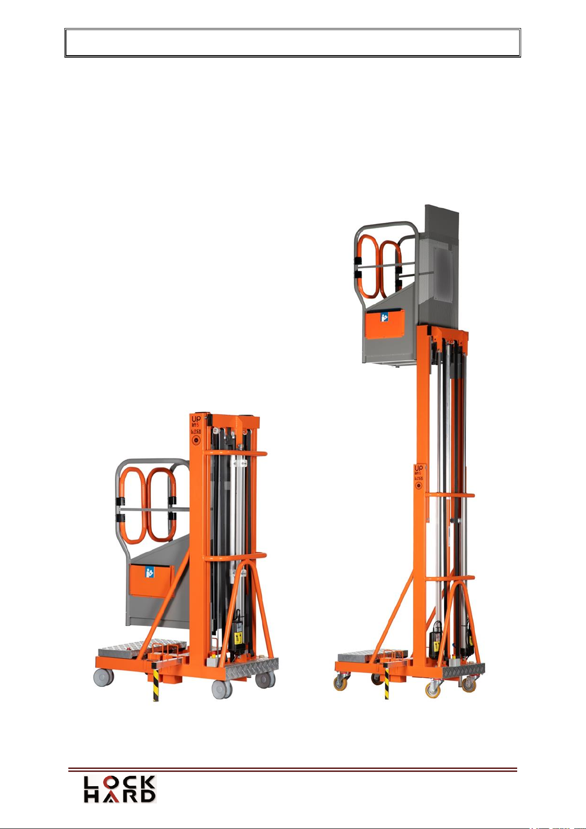
Lift Up Lift 5 120 - is a mobile machine designed to lift people and loads in a basket. The
device consists of a base, a moving mast, a basket with controls and a drive system.
Basket - a part of the lift with automatically closed gates, used to move the operator to the
desired working position.
Operator - a person, adequately trained and authorised to operate lifting devices.
Rated safe working load - the maximum permissible mass to be lifted in the basket. Rated
safe working load includes the weight of the operator, tools and materials placed in the basket.
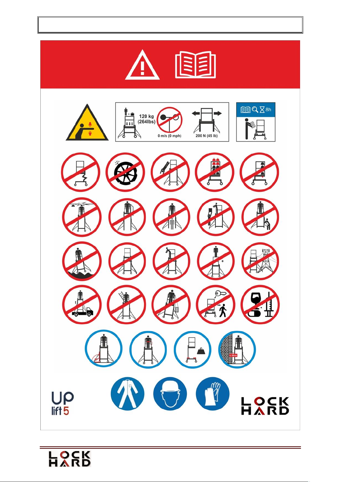
1.4. Safety symbols used in the manual
The following symbols are used to draw attention to points in this manual that contain
important information or indicate hazards. When reading the operating manual, pay special
attention to the points marked with these symbols.
Danger
This symbol indicates a direct threat to life and health. Failure to comply
with the rules means danger to life or risk of serious injury and significant
material damage.
Note
Indicates a warning against possible damage to the lift or other property in
the event of improper performance of the indicated activity.
1.5. National requirements
In addition to this operating manual, read the applicable national and local statutory
regulations and other regulations in force concerning work safety. The above requirements
also applies to the rules of working at heights and environmental protection in a given
country.
In Poland, Up Lift 5 120 is a machine qualified as handling equipment and the operator must
have the appropriate qualifications to operate handling equipment of type IP or IIP confirmed
by the Office of Technical Inspection.
Legal basis:
Regulation of the Council of Ministers of 7.12.2012 on the types of technical devices subject
totechnical inspection ( Polish Journal of Laws of 2012, No. 0, item 1468), issued on the basis
of Article 5 paragraph 2 of the Act on technical inspection.
Pursuant to the Polish Regulation of the Ministry of Economy, Labour and Social Policy of
29.10.2003 about technical conditions and technical inspection in the scope of operation of
certain handling equipment. In accordance with Section 25.1, Point 6, after changing the
location of the UTB, no ad-hoc operational inspections of the device with single-phase power
supply are required.
OPERATING MANUAL Up Lift 5 120
January 2023
Page 7
1.6. Declaration of Conformity –template
EU DECLARATION OF CONFORMITY
Manufacturer: LOCKHARD Sp. z o. o.
ul. Ostrowska 74A
63-410 Gorzyce Wielkie
www.lockhard.eu
Product: UP Lift 5 120
Serial number: …………………….
We hereby declare that the product specified above complies with the essential health and
safety requirements contained in EN 280+A1:2015-11 and EN 60204-1:2018-12.
Certificate of conformity issued by JS Hamilton Ltd. No. JSHP/44/CZ/2020.
The product is marked with the mark:
Place of storage of technical documentation:
LOCKHARD Sp. z o.o.
ul. Ostrowska 74a
63-410 Gorzyce Wielkie
Technical Director:
Łukasz Leonhard
Gorzyce Wielkie, date …………… ……………………………………
OPERATING MANUAL Up Lift 5 120
January 2023
Page 8
1.7. Intended use of the man lift
Up Lift 5 120 is intended only for vertical lifting of people to work position where they work
from the basket, assuming that these people enter and leave the basket in its lower position.
1.8. Technical data
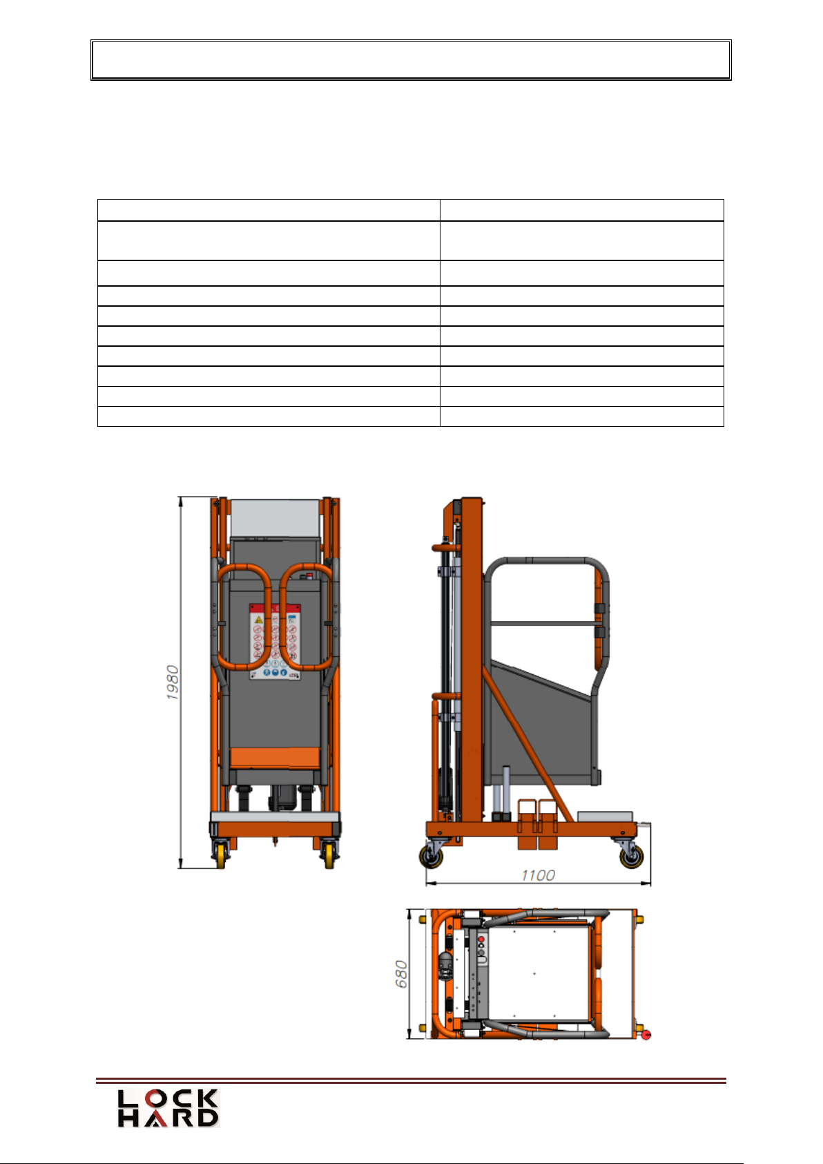
Maximum load in the basket
120 kg (1 person + tools)
External dimensions (WxLxH)
Working surface dimensions (WxL)
680 x 1100 x 1980 mm
480 x 690 mm
Maximum lifting speed
10 m/min. (at full battery power)
Maximum lifting height
2,90 m
The weight of the lift
AS/100 HD/115 kg + 60 kg ballast
Supply voltage
12 V DC
Battery capacity
39 Ah
Battery voltage
12 V
Temperature of use
-15°C to +40°C
Noise level
Does not exceed 70 dB
2. CONSTRUCTION OF THE LIFT
2.1. Drawing

OPERATING MANUAL Up Lift 5 120
January 2023
Page 9
OPERATING MANUAL Up Lift 5 120
January 2023
Page 10
2.2. Base
The base with the load-bearing structure of the lift is made of welded steel hollow sections.
The lift is moved by wheels with a foot brake (Up Lift 5 120 HD) or with an automatic lock
(Up Lift 5 120 AS). A 60 kg ballast and side stabilizers are used to ensure the lift's stability.
2.3. Power unit
Up Lift 5 120 basket is lifted by an electric actuator, which are permanently attached to the
support frame of the base on one side and to the movable mast on the other side. The LA36
electric actuator is assisted by gas springs. The basket is lifted through a system of belt slings
and mast.
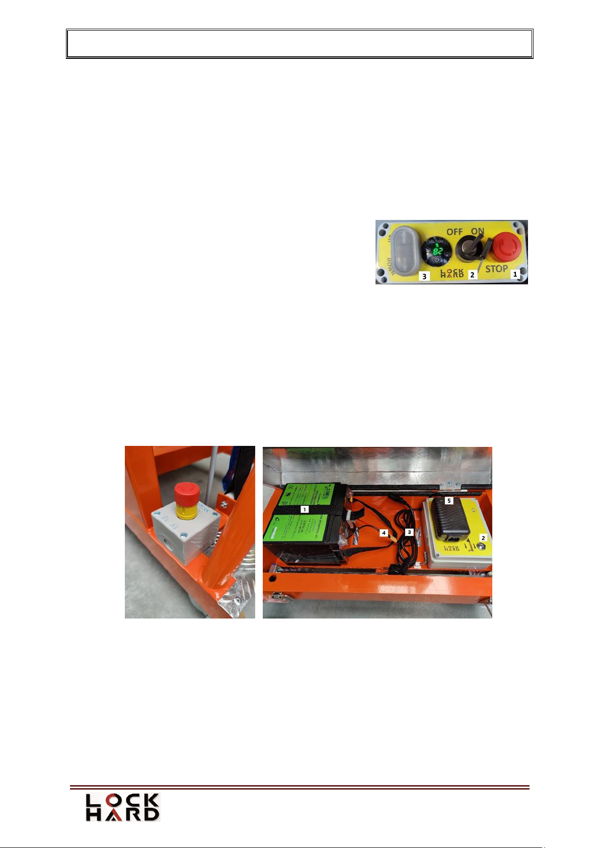
2.4. Control panel
The control panel is located in the basket. There is a key
switch on the panel (Fig. 1/2) and three buttons - a red
emergency stop button (Fig. 1/1) and two buttons used to
control movements (Fig. 1/3).
2.5. Electrical box
At the base of the lift an electric box is located. Access to the box is possible after lifting the
basket. The box contains the following items:
emergency lowering button (Fig. 3/2);
12 V/39 Ah batterie (Fig. 3/1);
battery charger 110 V/230 V AC →12 V DC/10 A (Fig. 3/5);
110 V/230 V AC cable with a plug (Fig. 3/3).
XT60 connector (Fig. 3/4).
Figure 2. Emergency button Figure 3. Electrical box
3. OPERATING MANUAL
The lift may only be operated by a properly trained and authorized operator who has read and
understood these instructions and complies with the regulations on the proper use of the lifts
in the user's country.
Figure 1. Control panel
OPERATING MANUAL Up Lift 5 120
January 2023
Page 11
The user is responsible for the safe installation and operation of
the UP Lift 5 120.
3.1. Preparation
Before starting operation, the lift must be checked for technical condition and possible
defects. It is necessary to inspect the supporting structure, belts and the power unit. If any
faults are detected, do not use the lift. Make sure that all control and protection devices are
ready for operation and check the voltage on the digital display. If the voltage is lower than
10.5 V, charge the batterie.
3.1.1.Environmental control
In the area where the lift is to be operated, the surroundings should be checked for possible
hazards, e.g. For electrical cables, ruins, rubble, excavations, mobile cranes, pedestrian traffic,
vehicle or machinery traffic, etc. in the vicinity of the lift. Gradient in the area should not
exceed 0. 5°. If there is a risk of contact of the lift with power lines, voltage in the lines
should be cut off. The work position where the lift is operated must be protected against
access by unauthorised persons.
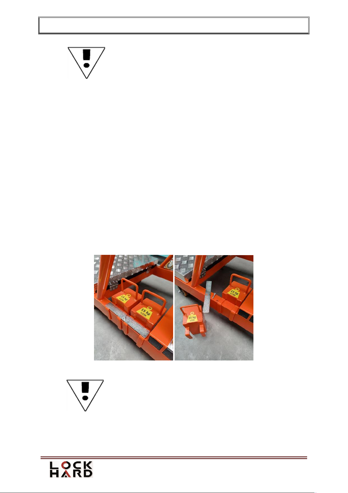
3.1.2.Installation of ballasts
In order to use the man lift properly and safely, ballasts on the base must be installed (Fig. 4).
Properly placed ballasts should be secured with a bolted plate. The wrench needed to tighten
the bolts is in the junction box. The total weight of the ballast is 60 kg (4x 15 kg/33 lbs).
When the work is finished, it is not necessary to remove the ballasts.
Figure 4. Ballast installation
IMPORTANT!
Ballasts must be fitted always when
the lift is operated!
OPERATING MANUAL Up Lift 5 120
January 2023
Page 12
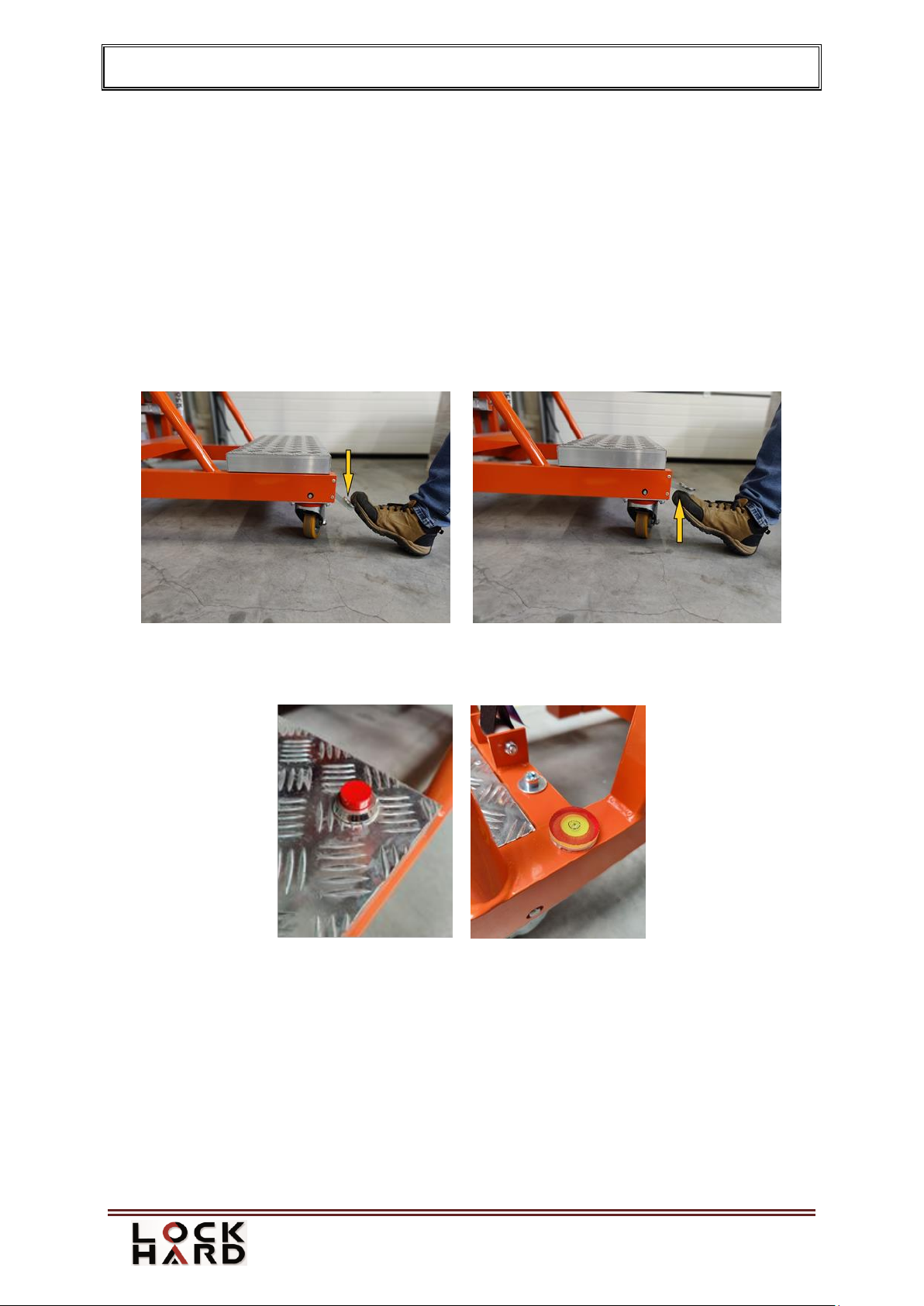
3.1.3.Moving the Up Lift 5 120
The lift should be pushed manually on the smooth, horizontal, solid and free of obstacles
ground. Exercise extreme caution when moving the lift. The lift can be moved with the
ballasts attached. After reaching the target place of work, lock the wheels with the foot brake
(Up Lift 5 120 HD) - the wheels can be locked by pressing the foot lock (Fig. 5). To unlock
the wheels, lift the wheel lock with your foot (Fig. 6).
In case of the Up Lift 5 120 AS, the locking process occurs automatically when the basket is
raised to a height of approximately 5 cm. To unlock the automatically locked wheels, lower
the lift basket as far as possible and then press the red button at the base (Fig. 7.) and at the
same time set the control panel switch to the "DOWN" position. This lowers the basket to the
transport position and unlocks all the running wheels.
Figure 5. Wheel lock Figure 6. Unlocking the wheels
Press the pedal to lock Release the pedal to unlock the wheels
A spirit level is installed on the base to control the horizontal position of the lift. (Fig. 8).
Figure 7. Red button Figure 8. Spirit level
3.1.4.Stabiliser feet
To ensure safe operation of Up Lift 5 120, it is absolutely necessary to unfold the side
stabiliser feet as described below:
Press in the locking pin (Fig. 9 and 10) and pull out the feet from the socket (Fig. 11).

OPERATING MANUAL Up Lift 5 120
January 2023
Page 13
Figure 9. Locking pin Figure 10. Pressed locking pin
rotate the stabiliser feet 180°
insert the rotated stabiliser feet into the socket (Fig. 12 and 13) until it locks on the
hole (Fig. 14).
Figure 11. Pulling out the feet from the socket Figure 12. Inserting the rotated stabiliser feet
Figure 13. Inserting the rotated stabiliser feet Figure 14. Locked locking pin
perform the above steps for both feet.

OPERATING MANUAL Up Lift 5 120
January 2023
Page 14
Figure 15. Unfolded the side stabiliser feet
IMPORTANT!
Stabilisers must be fitted every time
the lift is operated!
using the lift at a distance of less than 30 cm from the wall is allowed after fitting
the stabiliser feet on one side (Fig. 16).
Figure 16. One-sided unfolding the stabiliser feet
IMPORTANT!
It is forbidden to use Up Lift 5 120 without properly installed
ballasts and stabilisers

OPERATING MANUAL Up Lift 5 120
January 2023
Page 15
3.2. Operation of the lift
The lift can be operated by one person, the control position is in the basket and the operator
may enter or leave the basket only when it is lowered.
3.2.1.Control panel operation
make sure the emergency stop buttons are not activated.
turn the key to "ON" position (Fig. 1/2).
control the basket movement using the "UP" or "DOWN" buttons marked with arrows
(Fig. 1/3). In order to move the basket up and down, the button must be kept pressed.
During lifting or lowering of the basket, operator and materials
must stay within the outline of the basket floor.
If any hazards occur, stop the basket movement with the emergency stop buttons (Fig. 1/1 and
Fig. 2) - after pressing the red button, the lift stops. The button must be turner to reactivate the
power unit.
The up/down button cover protests the button against contamination. Replace the cover if
damaged!
3.2.2.Completion of work
After completing the work, it is necessary to:
lower the basket to the lowest position;
turn the key in the main switch (Fig. 1/2) to "OFF" position, remove the key from the
main switch to prevent unauthorised persons from using the lift;
step out of the basket,
fold the stabiliser feet;
leave the lift in a safe place,
lock the wheels with the brake,
connect the battery for charging.
3.2.3.Removal and reinstalation of batteries
Make sure that the basket is in a position that allows the
battery cover to be opened and that no people or material
are present in the immediate vicinity.
OPERATING MANUAL Up Lift 5 120
January 2023
Page 16
Figure 17. XT60 connector
Up Lift 5 120 is delivered with the battery installed. During operation, however, it may be
a need to remove and reinstall them:
raise the basket to a height that allows the electric box
cover to be opened - approx. 40 cm;
open the cover;
disconnect the battery by removing the XT60
connector (Fig. 17);
remove the battery from the box;
close the cover;
use the clamp to secure the cover against unintentional
opening.
To reinstall the battery:
Make sure that the basket is at the right height,
Put the battery in the box,
Connect the batteries by connecting the XT60 connector (Fig. 17).
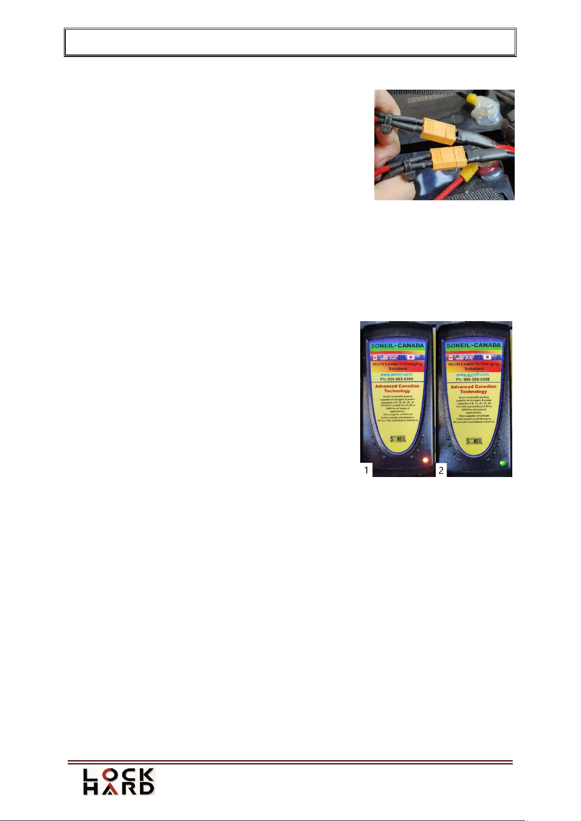
3.2.4.Charging the batteries
To charge the battery:
connect the wire to the electric box;
connect the cable to the mains supply 110/230 VAC;
extension cords can be used for this connection
according to EN IEC 61316:2021;
while charging, the indicator lamp on the charger
lights up red (Fig. 18/1). The indicator lamp will
turn green when the battery is fully charged (Fig.
18/2);
Once the battery is charged, disconnect the cable
from the mains and the electrical box.
More information on the charger is given in Chapter 9.
In the event of a longer period of storage of the battery, the lift should be charged at least once
a month for at least 12 hours.
3.2.5.Overload
Up Lift 5 120 is equipped with a system preventing the basket from being overloaded. If the
basket cannot move upwards, it means that the basket has been overloaded and the weight
should be reduced. Overload is signalled by an acoustic signal. In the event of severe
overload, the fuse in the switch box may need to be replaced.
Figure 18. Battery charger

OPERATING MANUAL Up Lift 5 120
January 2023
Page 17
3.2.6.Emergency lowering
If the operator cannot lower the basket due to a failure of the control system or indisposition
of the operator, emergency lowering of the basket can be activated. Up Lift 5 120 is equipped
with two emergency lowering systems, the operation of which requires the intervention of an
outside person who will be able to bring the basket to its lower position by means of:
a) electric emergency lowering system -the emergency exit button is located under the
cover of the electric box (Fig. 19). To lower the basket, press and hold the button. The
button will not work if one of the Emergency Stop buttons is activated. Use of the
electric lowering system in situations other than emergency situations and
simultaneous use of the emergency lowering system with the main control system is
forbidden and may lead to mechanical failure of the lift.
Figure 19. Electric lowering system Figure 20. Mechanical lowering system
b) emergency lowering system - with the bolts at the bottom of the actuators (Fig. 20).
To lower mechanically, remove the cover and turn the bolts with a 6 mm Allen key.
Turn both bolts evenly.
If the basket is blocked in the supporting structure, do not take any actions to restart the lift.
Supervisors should decide on how to safely evacuate the operator from the bin.
In the event of a mechanical or electrical failure, please contact an authorized service
technician of Lockhard Sp. z o.o.
Always follow the safety rules in this manual.

OPERATING MANUAL Up Lift 5 120
January 2023
Page 18
4. RESIDUAL RISK
Table 1. Potential dangers of improper use of the Up Lift 5 120.
Danger!
Risk of injury
Risk of crushing due to lack of space
There is a risk of crushing if unauthorised persons
are under the lowering basket. The risk arises in the
event of breaking the ban on access to the basket.
Risk of crushing and abrasion of the
skin
Risk of injury caused by extending a limb beyond
the basket floor outline and leaning out during the
vertical movement of the basket.
Lack of personal protective
equipment
If personal protective equipment is not used, bodily
injuries may occur, e.g. abrasions, cuts.
Human errors
Human errors may occur if the operating manual is
not followed or due to the lack of proper training,
which may result in loss of life or health, damage to
the machine and all related costs.
Assembly errors
Assembly errors may occur if the assembly
instructions are not followed, which may result in
loss of life or health, damage to the machine and
improper functioning of the machine.
Falling or thrown objects
During working in a basket, the employee is obliged
to secure the materials stored in it.
Loss of stability/tipping over
Failure to follow the operating manual may result in
loss of stability and overturning of the machine,
which may result in damage to the machine,
personal injury or death.
Slipping, tripping or falling people
The risk of slipping may occur in the event of poor
maintenance of the basket and when the floor
surface is slippery due to dirt. A tripping hazard can
occur if the materials are not positioned correctly in
the basket.
No maintenance
May result in a complete failure, which can cause
injury to the operator, loss of health, damage to the
environment and property.
Operation by an unauthorised person
Risk of injury may occur if an unauthorised and
untrained person is in the basket or in its immediate
vicinity.
Overload may result in overturning
When the basket is overloaded, stability can be lost.
Caused by difficult
assembly/use/maintenance
conditions. Use of inappropriate
parts.
In the case of difficult conditions for assembly,
disassembly, use and maintenance, human errors
may occur, e.g. incorrect assembly, incorrect
selection of parts, poor maintenance, too much
hurry in the performed works.

OPERATING MANUAL Up Lift 5 120
January 2023
Page 19
Instructions for recognition and rectification of failure and restart.
Table 2. Probable causes of failures of Up Lift 5 120 and remedies
Failure
Probable cause
Remedies
Stopping the
basket while
it is moving
Overloaded basket (burned fuse)
Check the basket load, reduce load,
replace fuse.
Battery discharged
Drive to the lower position, replace or
recharge the battery
Contamination in the "UP-
DOWN" button
Replace the button, blow out the buttons
with compressed air
Electrical actuator cable damaged
Fix the cable
Microcomputer failure
Replace the microcomputer
5. SAFETY GUIDELINES
5.1. Using the lift inconsistently with its intended use
When using UP Lift 5 120 man lift, it is forbidden to:
Lifting more than one person in the basket;
Moving the lift with operator in the basket;
Moving the lift by towing with motor vehicles such as a car, forklift truck, tractor, etc.;
Working in the basket near energised electrical appliances;
Using lift in potentially explosive atmospheres;
Using the lift as a crane;
Using the lift as a supporting structure for hanging manual or mechanical winches;
Standing on the basket's handrails or other elements out into the basket, e.g. a ladder,
toolbox, etc.;
Putting platforms between the lift and another structures (buildings, scaffolding, etc.);
Resting objects against the structure of the lift during operation;
Using a lift that is not serviced and has not passed the technical inspection;
Simultaneous using the control panel and the emergency lowering system;
Leaving and using a lift during rainfall and wind;
Lowering the basket if there are bystanders or any obstacles under it;
Horseplay while using Up Lift 5 120;
Lowering a stuck basket;
Using Up Lift 5 120 with open gate;
Dragging wires, ropes etc. from the floor to the basket.
Raising the basket when transporting the lift.
5.2.Additional rules
Depending on the type of work performed with the lift, use personal protective
equipment: work clothes and the equipment to protect your head, eyesight, hearing and
limbs.
When operating Up Lift 5 120 do not wear loose clothes, scarves, jewellery, etc.
UP Lift 5 120 is not equipped with its own lighting, therefore the user should ensure
proper lighting of the workplace from an external light source.

OPERATING MANUAL Up Lift 5 120
January 2023
Page 20
6. STORAGE AND TRANSPORT
Up Lift 5 120 should be stored in rooms with paved floors, adequately protected against rain
and snow. Avoid dust, grease or other contamination. The battery should be stored at a
positive temperature in accordance with the operation and maintenance manual.
7. MAINTENANCE
7.1. Definitions
Maintenance man - a person duly authorised to carry out maintenance duties on the lifts in
accordance with the regulations in force in the user's country. In Poland –a person authorised
by the Office of Technical Inspection to maintain handling equipment in P. Category (Mobile
Platforms).
Service technician - is a person who has been properly trained by the manufacturer of Up
Lift 5 120. Periodic replacement of components or ad hoc repairs of the lift may be performed
by the manufacturer's service or service units authorised by the manufacturer.
7.2. Maintenance and inspection schedule
Maintenance inspections should be performed every 90 days by an authorised operator. The
environment in which the lift is operated and the frequency of use may affect the maintenance
schedule.
List of inspection or maintenance activities:
1. Visual inspection of the superstructure;
2. Belts inspection;
3. Functional check
4. Cleaning, lubrication of mechanical parts;
5. Replacement of illegible stickers and instructions;
6. Checking the electrical system. Cables, connections and insulation
7. Battery connection check
7.3. Maintenance inspections - additional remarks
The purpose of the inspection is to check:
The technical condition of the drive mechanisms, brake systems, load-bearing
structure, in particular welded joints,
The assembly of the belts, gas springs and the actuator. Operation of safety and
emergency stop systems. Button operation.
The maintenance man is obliged to:
Log the maintenance of the Up Lift 5 120 lift in the machine log book with the date and
signature confirming the result of the inspection and the scope of the activities performed.
In the event of irregularities, the maintenance man as the person responsible for the Up Lift
5 120 makes a decision about the need to take the lift out of service.
7.4. Ad hoc and service inspections.
Occasional inspections of the lift should be performed after a break in operation lasting longer
than 2 weeks (when the lift is fully assembled but not in use). The operator is responsible for
performing ad hoc inspections. The results of ad hoc inspections should be recorded in the Up
Lift 5 120 log book by the persons performing the inspection.
Table of contents
Other Lockhard Lifting System manuals


Popular Lifting System manuals by other brands

probst
probst SDH-H-15 operating instructions

Bruno
Bruno OUTDOOR ELITE CRE-2110E Operator's manual

matev
matev FPS Mounting Assembly Installation Guide

Vestil
Vestil CYL-HLT Series instruction manual

Butts Tools
Butts Tools BXS0002 operating instructions

Safelift
Safelift MoveAround MA60 Original instructions


R. Beck Maschinenbau
R. Beck Maschinenbau HS 600 operating manual

Nova Technology International, LLC
Nova Technology International, LLC NAS Series quick start guide

Genie
Genie Z-60/34 Operator's manual

Screen Technics
Screen Technics INTERFIT Vertical Up Lift instructions

Drive
Drive DUPONT SAMERY Hermes user manual

Custom Equipment
Custom Equipment Hy-Brid 3 Series MAINTENANCE & TROUBLESHOOTING MANUAL