Locknetics Pro 9100 Series Assembly instructions

Description of Operation
575 Birch Street, Forestville, CT 06010
Phone (860) 584-9158 Fax (860) 584-2136
www.locknetics.com
- PAGE 1 -
FORM 77027 Rev. B 5/99
Pro Access System
BATTERY POWERED LOCK WITH ACCESS CONTROL
INSTALLATION AND WIRING INSTRUCTIONS
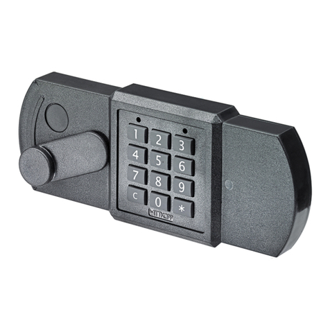
The Pro Controller provides a simple solution to access control needs. Providing 20 user
code capability through manual programming, this is a new and simple product to install and
program. The Pro is available in hard wired or battery powered versions. The battery pow-
ered device may be used with any Locknetics motor driven locking device, such as the
9100BP or the 443 Cabinet Lock. The hard wired unit will work with any 12 or 24 VDC lock-
ing device, such as a magnetic lock or electric strike, not requiring any more current than 5
amps. Access control is now as easy as 1) install locking device, 2) install keypad, 3) plug
and play!
Pro 9100 Series
Power Strike
STANDARD
Pro 443 Series
Cabinet Lock
9” LOCK FRONT
FOR WOOD FRAMES
TO REMOTE
RELEASE INPUT
DEVICE
PRO CONTROLLER
KEYPAD
BATTERY PACK OR
HARD WIRED
BOARD
BATTERY POWERED
MOTOR DRIVEN
LOCK OR HARD
WIRED DEVICE

- PAGE 2 -
FORM 77027 Rev. B 5/99
Pro Access System
BATTERY POWERED LOCK WITH ACCESS CONTROL
INSTALLATION INSTRUCTIONS
1. INSTALL MOTOR DRIVEN LOCKING DEVICE
Follow the template and installation instructions provided with the locking device.
2. INSTALL SINGLE GANG BOX
Install single gang box in wall. Run wiring from locking device to gang box. Secure
battery pack inside the gang box.
3. INSTALL KEYPAD
Attach all wire connections as shown. Mount keypad to gang box.
HARD WIRE OPERATED\
SINGLE GANG MOUNT
HELPFUL HINTS
Battery pack must be
accessible after instal-
lation for battery
replacement.
Both the single gang
and narrow style pro
keypads are capable
of battery or hard
wired operation.
When the battery pack
is being used in the
installation, a gang
box or similar device
must be used to sup-
port the battery pack.
BATTERY OPERATED\
NARROW STYLE MOUNT

- PAGE 3 -
FORM 77027 Rev. B 5/99
Pro Access System
BATTERY POWERED LOCK WITH ACCESS CONTROL
INSTALLATION INSTRUCTIONS
To battery powered
locking device
Pro keypad \ controller
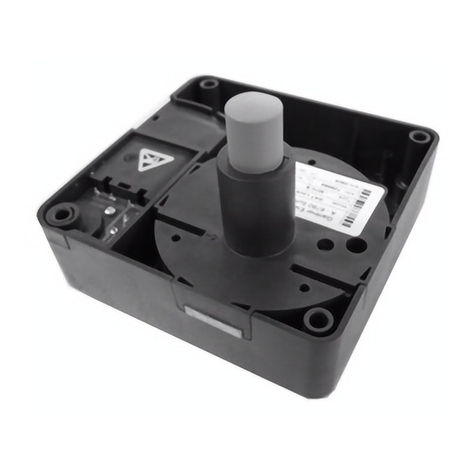
Plug in connec-
tors
Battery pack
BATTERY OPERATED
1. Plug keypad into
battery pack 4 pin con-
nector.
2. Plug battery pow-
ered locking device into
battery pack 2 pin con-
nector.
To 12\24 VDC power
supply
To hard wired
locking device
Pro keypad \ controller
Position switch
towards connector for
a fail safe lock.
Position switch away
from connector for a
fail secure lock.
HARD WIRED
1. Plug keypad into cir-
cuit board.
2. Apply 12 or 24 VDC
to red and black wires.
Be sure to observe
polarity.
3. Connect blue and
brown wires to locking
device power. Again
be sure to observe
polarity.
4. Position switch as
shown for fail safe or
fail secure locking
devices.
NOTES FOR BATTERY AND HARD WIRED SYSTEMS
1. The maximum current that can be put through the hard wired Pro Controller is 5 amps.
2. Battery life of the battery operated Pro Controller is 80,000 cycles.
BLACK (-)
WHITE (+)

- PAGE 4 -
FORM 77027 Rev. B 5/99
Pro Access System
BATTERY POWERED LOCK WITH ACCESS CONTROL
INSTALLATION AND WIRING INSTRUCTIONS
DEFINITION OF CODE FUNCTIONS AND FACTORY DEFAULTS
MASTER 97531 Allows access to programming functions. Will not release lock.
NORMAL 13579 Unlocks lock for relock time delay.
ACCESS
TOGGLE 135135 Unlocks the lock until same or another Toggle Code is entered.
LOCKOUT 9115 “Freezes” the lock in its present condition, either locked or unlocked, and will
not accept any user codes until the same or another Lockout Code is entered.
FACTORY DEFAULT
ERASE MEMORY
Memory may be erased to conveniently return to default time delay settings or if an error was made.
1. Disconnect power.
2. Press any button one time.
3. Reapply power. Red and green LEDs flash alternately.
4. Press * key 3 times quickly immediately after LEDs stop flashing. Red and green LEDs flash alter-
nately.
NOTES:
All programmed codes will be erased. Factory default codes and time settings will be restored.
TO CHANGE CODES
Master Code *...1 *...Old Code*...New Code (3-8 digits) *...*(to end)
MORE CODES CAN BE CHANGED BY
RETURNING HERE.
TO ADD NORMAL ACCESS CODES - Will unlock door for relock time delay period. Will also reset lock after an alarm condition.
Master Code *...3 *...New Code (3-5 digits) *...*(to end)
UP TO 20 NEW CODES CAN BE
ADDED BY RETURNING HERE.
TO DELETE CODES
Master Code *...5 *...Old Code *...*(to end)
MORE CODES CAN BE DELETED
BY RETURNING HERE.
TO CHANGE MASTER CODE
Master Code *...7 *...New Master Code (5-8 digits)*...New Master Code *
TO ADD FUNCTION CODES (Note that a three digit function code sets the function of the user code)
Master Code *...33*...111*...New Access Code (3-7 digits) * ...*(to end)
DOUBLE USE CODES (The two codes programmed must both be entered before access will be granted)
Master Code *...33*...117*...First user code (3-7 digits) * Second user code (3-7 digits)..*
MORE CODES CAN BE ADDED BY RETURNING HERE.
OR
191*...New Toggle Code
OR
115*...New Lockout Code
OR
113*...New One-Time Access Code
PROGRAMMING INSTRUCTIONS

- PAGE 5 -
FORM 77027 Rev. B 5/99
Pro Access System
BATTERY POWERED LOCK WITH ACCESS CONTROL
INSTALLATION AND WIRING INSTRUCTIONS
Battery Operating Information
Low Battery Indication:
When a valid code or is entered the green LED will flash during the unlock
time. If the batteries are weak, the red LED will flash for several seconds before the
green LED flashes. This is the indication to change the batteries.
Checking the Batteries:
Set the voltmeter for DC voltage at a scale above 6 volts. Place the meter probes
onto the two outer connectors of the four pin battery harness.
VOLTMETER READING
6.2 VOLTS
4.5 VOLTS OR LESS
BATTERY CONDITION
FRESH BATTERIES -FULL STRENGTH
REPLACE BATTERIES
Replacing the Batteries:
1. Remove the four dead batteries and replace with four new batteries.
NOTES:
• Always replace batteries as a set.
• Use only quality alkaline batteries.
ERROR CODE CHART
An error has occurred when the red LED
stays on solid and the green led flashes
N times. Count the green flashes and
refer to the chart below.
N ERROR DESCRIPTION
2 CODE TOO LONG
3 MEMORY FULL
4 CAN’T DELETE MASTER CODE
5 2nd MASTER ENTRY NOT
SAME AS 1st
6 INVALID COMMAND
7 NOT USED
8 CODE TOO SHORT
9 DUPLICATE CODE
12 LOCKOUT
RELOCK DELAY
1. Enter master code.
2. Enter 9 9 *.
3. Press * key for the desired relock time. The red LED will blink once for each second.
FAIL SAFE
WIRING EXAMPLE
FAIL SECURE
WIRING EXAMPLE
This manual suits for next models
1
Table of contents
Other Locknetics Lock manuals
