manuals.online logo
Brands
  1. Home
  2. •
  3. Brands
  4. •
  5. Lodar
  6. •
  7. Microphone System
  8. •
  9. Lodar PS002TS Series User manual

Lodar PS002TS Series User manual

Popular Microphone System manuals by other brands

INIM SAGITTARIUS VW2W instructions

INIM

INIM SAGITTARIUS VW2W instructions

AKG IVM 4500 User instructions

AKG

AKG IVM 4500 User instructions

Earthworks Audio PM40 manual

Earthworks Audio

Earthworks Audio PM40 manual

Nady Systems ENCORE 2 owner's manual

Nady Systems

Nady Systems ENCORE 2 owner's manual

Oklahoma Sound WM-200H instruction manual

Oklahoma Sound

Oklahoma Sound WM-200H instruction manual

Chiayo SDR-8200 Operation manual

Chiayo

Chiayo SDR-8200 Operation manual

Paso R824 quick start guide

Paso

Paso R824 quick start guide

Naxa NAM-982 instruction manual

Naxa

Naxa NAM-982 instruction manual

Xvive U3 user manual

Xvive

Xvive U3 user manual

Tekon DUOS installation guide

Tekon

Tekon DUOS installation guide

Heyuan Intelligence IOT-G2S-01 user manual

Heyuan Intelligence

Heyuan Intelligence IOT-G2S-01 user manual

Devine WMD-IE user manual

Devine

Devine WMD-IE user manual

LG LF-D7150 owner's manual

LG

LG LF-D7150 owner's manual

LD U305 HBH 2 user manual

LD

LD U305 HBH 2 user manual

Chainway URA8 user manual

Chainway

Chainway URA8 user manual

ORATOR D860TD instruction manual

ORATOR

ORATOR D860TD instruction manual

Sennheiser Evolution Wireless Digital EW-DX EM 2 quick guide

Sennheiser

Sennheiser Evolution Wireless Digital EW-DX EM 2 quick guide

Shure UA844 user guide

Shure

Shure UA844 user guide

manuals.online logo
manuals.online logoBrands
  • About & Mission
  • Contact us
  • Privacy Policy
  • Terms and Conditions

Copyright 2025 Manuals.Online. All Rights Reserved.

PS002TS Series Wireless System | Instructions
SAFETY
1. The receiver is designed to carry a maximum of 5 amps, with an individual output maximum of 3 amps. If you need to switch
higher currents, consider a different Lodar series that’s suited to switch up to 15 amps.
2. Lodar receivers MUST have an isolation switch to allow for registering a replacement transmitter and a fuse for safety.
3. Both the transmitter and receiver will switch off after 30 minutes of inactivity.
4. If the application requires heavy vibration, potting the system may be required for proper operation.
5. If the Lodar system is installed within a toolbox, an aerial accessory can be added for optimal frequency range.
STEP 1: RECEIVER INSTALLATION
A
Remove power to the battery and fuse.
WARNING: Vehicle batteries contain gasses which are ammable and explosive. Wear eye
protection and do not lean over battery while disconnecting. Do not wear metal jewelry.
B
Choose the optimal location.
• Mount the receiver as high as possible above ground.
• Avoid surfaces with heavy vibration.
• Avoid direct spray from wheels.
• In a hot climate, t in a shaded postition.
• Cable gland should face down or back.
• If the Lodar system is installed within a toolbox, an aerial
accessory can be added for optimal frequency range.
C
Mount the receiver.
• Bolt the two mounting holes to a at surface.
• The holes t two 3/16” bolts (not supplied).
D
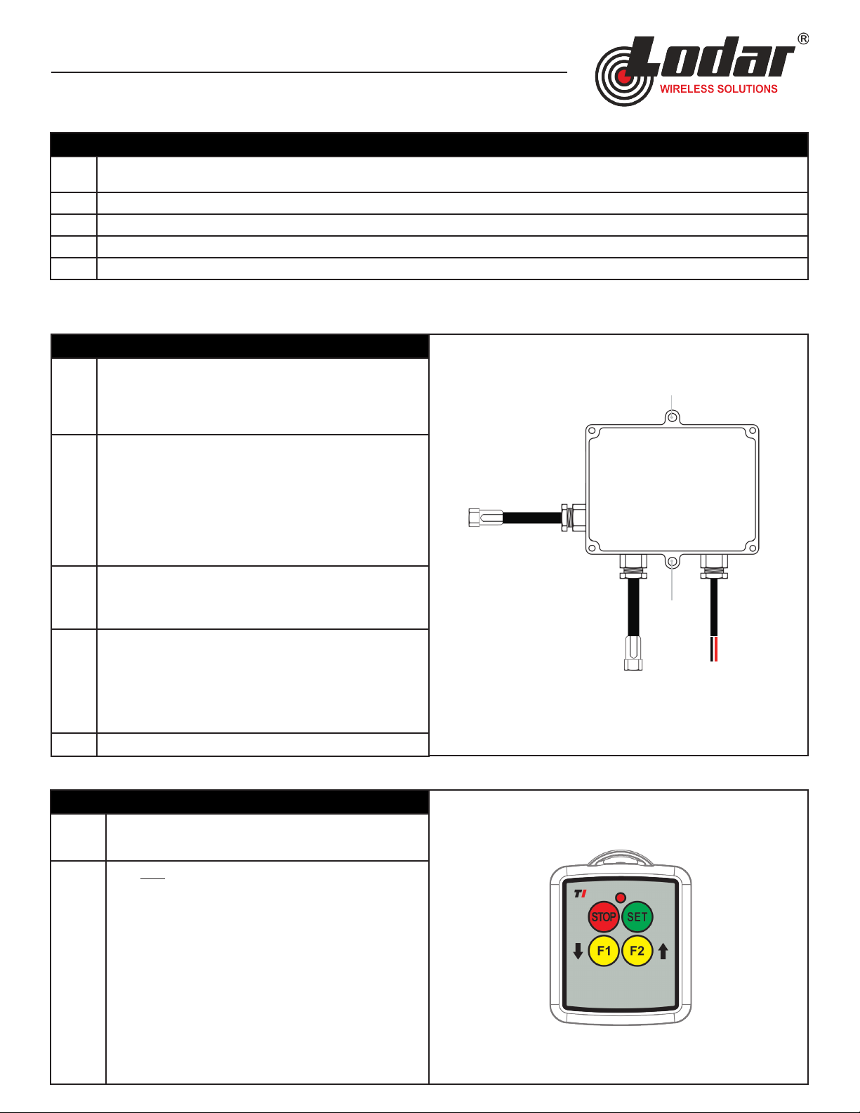
Wiring and quick connections.
• The red wire goes to the positive on the battery.
• The black wire goes to the negative on the battery.
• Quick connect the male end to the handheld wired control
plug.
• Quick connect the female end to the pump.
EReconnect power to the fuse and battery.
STEP 2: TRANSMITTER ACTIVATION
A
The transmitter is supplied with batteries that have been
disconnected. Connect the batteries.
B
Pair one transmitter to the receiver:
• Remove power to the receiver.
• Press and hold STOP (red) and SET (green) for a minimum
of 5 seconds. The transmitter will have the following light
pattern: ash pause, ash pause.
• Power the receiver.
• You have 10 seconds to press and hold the SET (green) for 5
seconds. The receiver will have a continuous light pattern.
• You are ready to control your equipment.
Mounting
hole
(3/16”)
Plug goes to
wired
handheld
control
Plug goes to
KTI® pumps
Power and
ground
connections
The PS002TS is specially designed for the work truck and trailer market to quickly install a
wireless system to a dump trailer. Compatible with KTI® pumps.
Mounting
hole
(3/16”)
FREQUENTLY ASKED QUESTIONS
Can I use a wired remote and wireless
remote at the same time?
Yes. The plug and play nature of the trailer series wireless allows the operator to use the wireless or the wired
hand control.
What is a transmitter? A wireless system consists of two main components: a transmitter (handheld wireless controler) and a receiver
(black box that’s mounted to your equipment). The transmitter sends messages to the receiver to operate your
equipment. The receiver receives the message and instantly responds by controlling the equipment.
What is a receiver?
Are replacement transmitters
available?
Transmitter and receiver parts are available. To reorder a transmitter, call your local dealer and give them the part
number on the lid of the receiver so they can identify the correct transmitter.
What is the warranty process if there
is a problem with my system?
The rst step in the warranty process is diagnoising the problem. First, change the transmitter batteries. Second, re-
pair the transmitter to the receiver using the “Transmitter Activation” instructions on page one. Third, if the system
is not responding, nd the serial number on the receiver, go to www.lodar.com/lodar-warranty to ll out a warranty
request form. Or call Lodar service at 877-257-1581 or send an email at [email protected]om.
Can I pair multiple transmitters
to the same reciever?
Yes. Below is the pairing process for multiple transmitters to the same receiver.
TROUBLE SHOOTING
In the event of a system failure, read the light on the receiver to learn more. Call Lodar service for warranty and technical help.
CONTACT US: Lodar | 549 U.S. HWY 287 S. Henrietta, Texas 76365 | Service 877-257-1581 [email protected] | Sales 940-538-5643 [email protected]om
CODING INTO SLOT 1
• Ensure Receiver is OFF
• Press and hold SET and STOP on Transmitter until LED goes OFF
• LED on Transmitter will ash once to indicate slot 1
• Turn ON Receiver
• Wait for yellow LED on Receiver to ash slowly
• Press and hold SET on Transmitter until SET on Receiver is illuminated
• Check Receiver is coded correctly by pressing SET then operating any function
CODING INTO SLOT 2
• Ensure Receiver is OFF
• Press and hold SET and STOP on Transmitter until LED goes OFF
• LED on Transmitter will ash once to indicate slot 1
• Press SET to select slot 2 – the LED on Transmitter will ash twice
• Turn ON Receiver
• Wait for yellow LED on Receiver to ash slowly
• Press and hold SET on Transmitter until SET on Receiver is illuminated
• Check Receiver is coded correctly by pressing SET then operating any function
F2 and M
F2