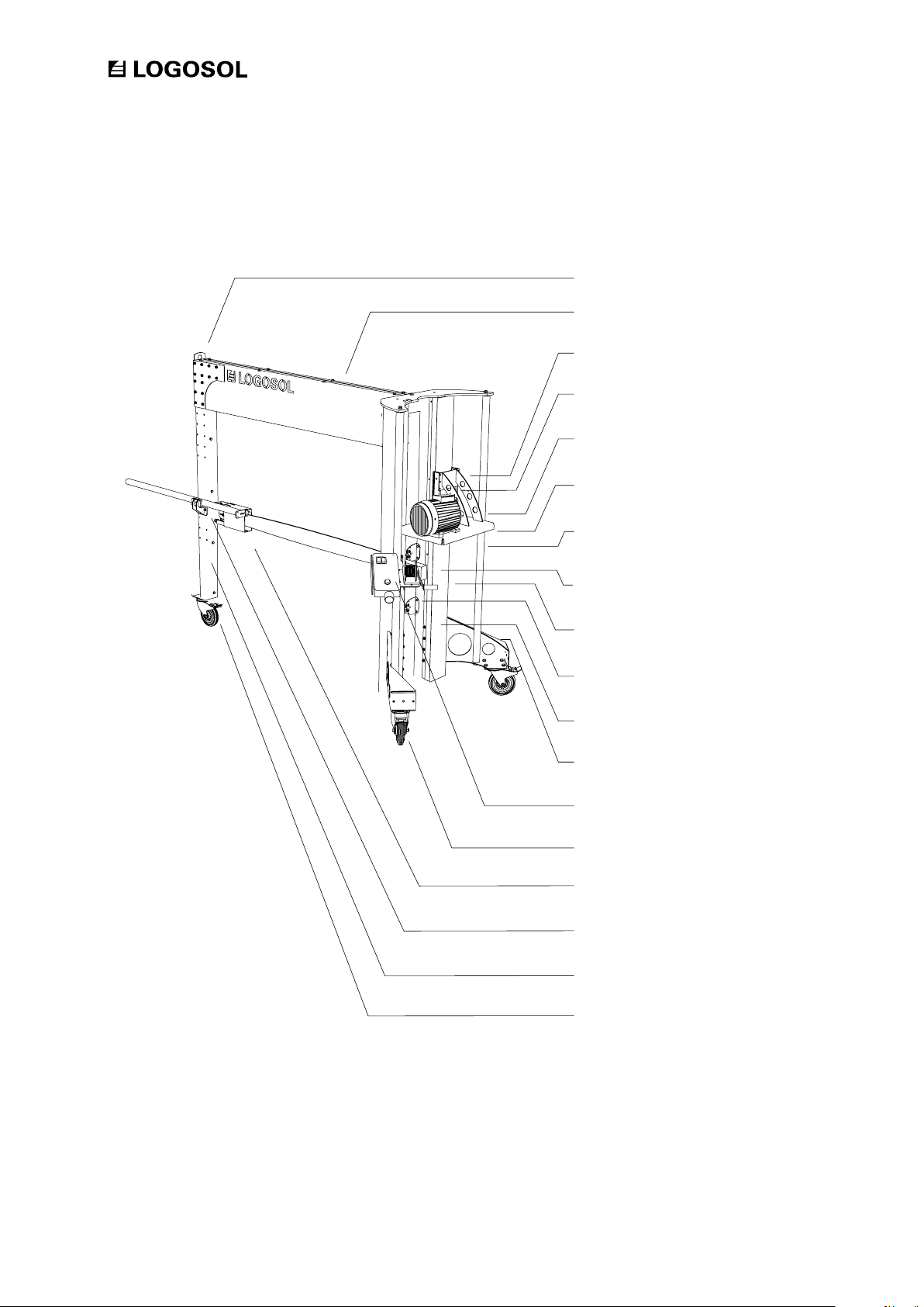
Logosol 0458-395-0603 User manual

BRUKSANVISNING
Ref. no. 0458-395-0603
LOGOSOL
STACK CUTTER PK 1500
EN

LOGOSOL continuously develops its products.
For this reason, we must reserve the right to modify
the conguration and design of our products.
Document: LOGOSOL PK1500 User Manual
Manual, artikelnr: 0458-395-0603
Text: Mattias Byström, Martin Söderberg, Robert Berglund
Illustrations: Mattias Byström, Martin Söderberg, Robert Berglund
Last revised: September 2018
© 2018 LOGOSOL, Härnösand Sweden
THANK YOU FOR CHOOSING A LOGOSOL MACHINE!
Read through the user manual carefully
and make sure you understand
its contents before you use the machine.
This user manual contains important
safety instructions.
WARNING! Incorrect use can result in
serious or fatal injuries to the
operator or others.
We are very pleased that you have demonstrated your condence in us by purchasing this product,
and we will do our utmost to meet your expectations.
Logosol has been manufacturing products since 1989. In that time we have supplied approximately
50,000 machines to satised customers the world over.
We care about your safety as well as we want you to achieve the best possible results with your
equipment. We therefore recommend that you take the time to carefully read this user manual from
cover to cover in peace and quiet before you begin using the product. Remember that the machine
itself is just part of the value of the product. Much of the value is also to be found in the expertise
we pass on to you in the user manuals. It would be a pity if that were not utilised.
We hope you get a lot of satisfaction from the use of your new machine.
Bengt-Olov Byström
Founder and chairman,
Logosol in Härnösand, Sweden
#1

Safety instructions 4
Machine description 6
Moving the Stack Cutter 7
Setting up the Stack Cutter 7
Components 8
Assembly 10
Adjustments 23
Preparations 26
Control panel 27
Stack cutting 28
End trimming 29
Setting the cut length 30
Changing cutting equipment 31
Troubleshooting – cutting equipment 32
Sharpening the chain 33
Maintenance 34
Material drying 35
Exploded views 36
Circuit diagram 46
Technical data 47
CE Declaration of conformity 48
TABLE OF CONTENTS

4
• Read carefully through the entire user manual
before starting to operate the machine. Failure
to observe these safety instructions may result in
fatal injuries.
• Make sure that everyone who uses the machine
is well informed of the dangers and has read
the user manual. The user manual shall always
be available to the persons working with the
machine. This also applies where the machine is
sold or loaned out.
• Minors under 18 years of age are not allowed to
operate the machine.
• Make sure that children and animals are not in
the vicinity when the machine is being operated.
• Respect the safety distances to avoid injury from
high noise levels.
• Anyone working with the machine must be
t for work, healthy and in good physical
condition. Make sure you take regular breaks
when operating the machine. Never operate the
machine while under the inuence of alcohol,
narcotics or other drugs or medicines that can
cause drowsiness or inattention.
• The machine is only to be operated where
visibility is good. It is not to be operated in the
dark or where visibility is poor.
• Make sure there are other persons within
earshot who you can summon if you need help.
• Always wear personal protective equipment:
Appropriate clothing is a tight-tting working
overall. Never operate the machine wearing
loose-tting clothes, overall coats or similar.
• Use safety shoes with high-grip soles and steel
toecaps. Neckerchiefs, ties, jewellery or other
items that can get caught in the equipment are
not to be worn.
• Wear strong protective gloves. Risk of cut
injuries when handling the guide bar and the
saw chain. Cutting equipment can also be hot
immediately after sawing.
SAFETY INSTRUCTIONS
Key to symbols
For your own safety, read through the entire
user manual carefully and do not start
the machine before you have understood
everything.
Use approved ear protectors and protective
eyewear. Hearing can be damaged even
after short periods of exposure.
Sharp rotating tools. Make sure that your
ngers never come near the cutting tools.
This symbol means ’WARNING’. Pay
particular attention where this symbol
appears in the manual text.
This symbol is followed by instructions that
must be observed. Pay particular attention
where this symbol appears in the manual
text.

5
PK1500 STACK CUTTER
SAFETY INSTRUCTIONS
During operation:
Do not start cutting until the steps in the section
”Preparations” on page 26 have been carried out.
Never start the stack cutter if the guide bar is not in
its top position and covered by the xed bar guard.
Never stick hands or tools under any guards or in the
cutting path of the guide bar.
Always stand with your face shielded by the
protective screen. When end trimming, the chain
can throw blocks of wood in the operator’s
direction.
On the same axis as the guide bar, with a 20
degree deviation to either side, the safe distance
“in front of” and “behind” the machine is 8
m (see the illustration). This also applies to the
operator. Besides the operator (shown as “Op” in
the illustration), no one may stand within 4 metres
of the machine’s sides while it is operating. The
illustration below shows a bird’s-eye view of the
machine. During operation, the operator must stay
within the indicated area behind the control panel.
The operator must not stretch his/her arms or legs
outside this area.
Risk of chain throw-off if the chain breaks.
Respect the safe distance!
Before releasing the winch safety catch, take a
rm grip of the winding crank. Except when the saw
unit is to be lowered, the safety catch should always
be on.
Risk of burns when changing the chain.
Cutting equipment can be hot after use.
A chip extractor (min. 700 m3/h) must be
connected during operation. Be aware of the risk
of breathing in dust. Saw outdoors or ensure good
ventilation.
Even people outside the safe distance may still
require ear protectors. Outdoors, the safe distance
for harmful noise is around 15 m. Ensure that no
one without ear protectors is exposed to sounds
above 70 dB(A).
Use non-toxic, vegetable, saw chain oil to
lubricate the chain.
Risk of unintentional start-up and electric
shock.
In this manual, the instruction ”cut the power”
always means unplug the power cable at the
control panel, hang it up so that neither the plug
nor the cable can be damaged, and ensure that
the chain has stopped.
Cut the power
- Before touching the chain in any way.
- Before attempting to free a jammed chain.
- Before servicing or other intervention involving the
guide bar, belt guard or electrical system.
- Before moving the machine.
- If the machine is to be left unattended. Also ensure
that no unauthorised person can start the machine.
- After tting a chain, ensure that it runs freely
before plugging the cable into the control panel.
Other safety instructions:
The machine must not be modied or added to. Use
only parts supplied by LOGOSOL. After servicing, the
machine must be restored to its original condition.
Risk of being hit by the winding crank.
Risk of the saw unit being lowered
unintentionally.
4M
4M
Operator
8M 8M

6
MACHINE DESCRIPTION
Sight
Adjustable wheel
Winding crank
Adjustable guide bar guard
Control panel
Guide rail
Winding crank safety catch
Lockable castor
Handle bar
Rear leg
Leg
Saw unit
Belt drive
Fixed guide bar guard
Oil tank
Lifting eye
Motor bracket
Sighting rod and holder

7
PK1500 STACK CUTTER
End trimming with Logosol’s Stack Cutter
Note where the operator is standing, the position
of his hands, that the guide bar nose guard is
pushed towards the stack, that the stack stands
rmly on at ground and that it is properly
strapped.
Max.
0.2m/sec.
Max.
0.2m/sec.
Thanks to its wheels, the STACK CUTTER can be
easily moved when required. Whenever possible, the
STACK CUTTER should be moved in the longitudinal
direction of the guide bar (i.e. not sideways). If
the STACK CUTTER is being moved more than a
short distance, the motor unit must be lowered to
its bottom position. The risk of tipping increases
considerably if the STACK CUTTER is moved sideways
(right/left). The oor over which the STACK CUTTER
is moved must be smooth and free from gravel and
anything else that can make the surface uneven.
Cut the power before moving the Stack Cutter.
Risk of tipping! The Stack Cutter may only be
moved on its wheels when the surface is smooth
and even.
Risk of tipping! The maximum permitted speed
when moving sideways is 0.2 m/sec. (1 m in 5 sec.).
When moving the machine, pay particular
attention to ensuring that the control panel does not
hit any obstacles.
When the machine is being moved, he winding
crank safety catch must always be on..
The Stack Cutter can easily be moved using a crane,
tractor or other equipment suitable for this purpose.
Use approved lifting straps/lifting chains. The Stack
Cutter has a lifting eye at the top of the rear leg. On
the motor-side, thread the straps or chains between
the handle bars and the guide rail.
SETTING UP
Read the entire manual and, before using the
machine, familiarize yourself with all the machine
functions and settings.
Inspect the Stack Cutter immediately on
reception. Any transport damage must be notied
immediately to the freight company.
Position the Stack Cutter on an even surface. Using
the crank on the adjustable wheel, adjust the
machine so that it is level and stable.
Connect the chip extractor hose and secure it with
hose clamps both at the the machine end and at the
extractor end.
Ensure that the lighting is rst-class. Fit a powerful
light above the machine.
Check that all bolts are rmly tightened. Check that
the saw chain runs freely and unobstructed on the
guide bar. Check that the chain has been tensioned
(see p.31).
MOVING THE STACK CUTTER

8
Manual
8200-005-0005
00-00000
00-00000
00-00000
00-00000
00-00000
00-00000
00-00000
00-00000
00-00000
00-00000
00-00000
00-00000
00-00000
00-00000
00-00000
00-00000
00-00000
00-00000
00-00000
00-00000
1x
2x
2x
1x
1x
1x
1x
1x
1x
3x
1x
1x
2x
1x
2x
1x
1x
1x
1x
2x
1x
Check that all components
are included in the shipment
when receiving the Stack
Cutter.
COMPONENTS

9
PK1500 STACK CUTTER
Motor kmpl 00-00000
1x
BOLT BAG
COMPONENTS – MOTOR BOX
M6x20
M5x20
28x
2x
M8x120
M6x120
17x
24x
M10x25
M10x35
M8x35
M8x20
M5x8
M10x30
7x
2x
8x
4x
4x
3x
M10
M6
M8
M5
M8
M10
M6
M8
M5
15x
45x
20x
2x
4x
32x
94x
56x
8x
M8x60
2x

10
10
Read all the assembly instructions
before beginning the assembly,
and then follow the step-by-step
instructions during the assembly.
Order of assembly
Good job!
Work on level ground, as this will facilitate
when adjusting the equipment.
1
PK-1500
The following symbols are used as supplements
to the symbols above to describe the design or
function of the fasteners.
Denition of fasteners.
The size of a fastener is written as a diameter
measurement (M) ISO 68-1. For bolts, this is
followed by a length measurement. The length of
the bolt is measured from below the head to the tip
of the bolt.
Low Tensilock Lock Countersunk
ADDITIONAL SYMBOLS
Allen bolt
Partial thread Allen bolt
Partial thread hex bolt
Hex bolt
Partial thread ange bolt
Flange bolt
Carriage bolt
Shoulder bolt
Phillips bolt
Slotted bolt
Set screw
Hex nut
Flat washer
Flange nut
BOLTS & NUTS
(Diameter)
DIAMETER & LENGTH
(Length)
M8 x 20

11
PK1500 STACK CUTTER
1
2
M8x20
8 x
3
M6x20
10 x
M6
4 x
M8
8 x
M6
14 x
PK-1500

12
4
5
6
M6x20
M8x120
M8x120
10 x
8 x
6 x
M8
M8
8 x
6 x
Tighten the bolt joints ngertight.
Note that the aluminium prole should be tted
such that it extend over the edge of the square
tube.
M8
M6
M8
16x
10 x
12 x
PK-1500

13
PK1500 STACK CUTTER
7
8
9
PK-1500

14
11
10
M10x30
M10x20/25
1 x
2 x
M6x120
3 x
M10
1 x
Place the motor bracket (raised by blocks) next to the
front leg. Fit the guide rail to the motor bracket and
then screw it to the front leg. Note that the holes in the
guide rail (four holes in a row) should point down. Wait
with the bolt joints for these holes, as these holes are to
be used for attaching the left leg.
Note that the top plate has to be tted such that it does
not extend over the edge of the rear leg, and that the
holes for the line pulley should be tted to the left.
M6
M10
6 x
4 x
M6
3 x
PK-1500
12
13

15
PK1500 STACK CUTTER
12
M10x25
4 x
13
M6x120
8 x
M10
M10
M6
2 x
4 x
8 x
M10
M10
M6
2 x
4 x
16 x
PK-1500

16
14
M10x25
M10x30
2 x
4 x
M10
M10
2 x
2 x
15
M10
M10
4 x
2 x
PK-1500
16
17
18

17
PK1500 STACK CUTTER
16
17
M8
M8
M8
2 x
2 x
2 x
Fit the sighting rod to the centre of the rear leg.
M8x120
2 x
M8x20
2 x
18
M8x60
2 x
M8
M8
M8
4 x
4 x
4 x
PK-1500

18
19
M6x120
12 x
M6
M6
M6
M6
12 x
12 x
24 x
12 x
PK-1500
20
21

19
PK1500 STACK CUTTER
20
21
2 x
2 x
Fit the line pulleys and the line holders in the holes
in the top plate, then thread the lifting line as in the
illustration.
M8
M5
M8
M5
M6
2 x
4 x
2 x
4 x
2 x
M8x20
M5x8
2 x
4 x
PK-1500

20
22
23
24
26
25
M5
2x
M5x20
2x
M5
4x
PK-1500
Table of contents
Other Logosol Cutter manuals