OM-ST-4E/6E 9
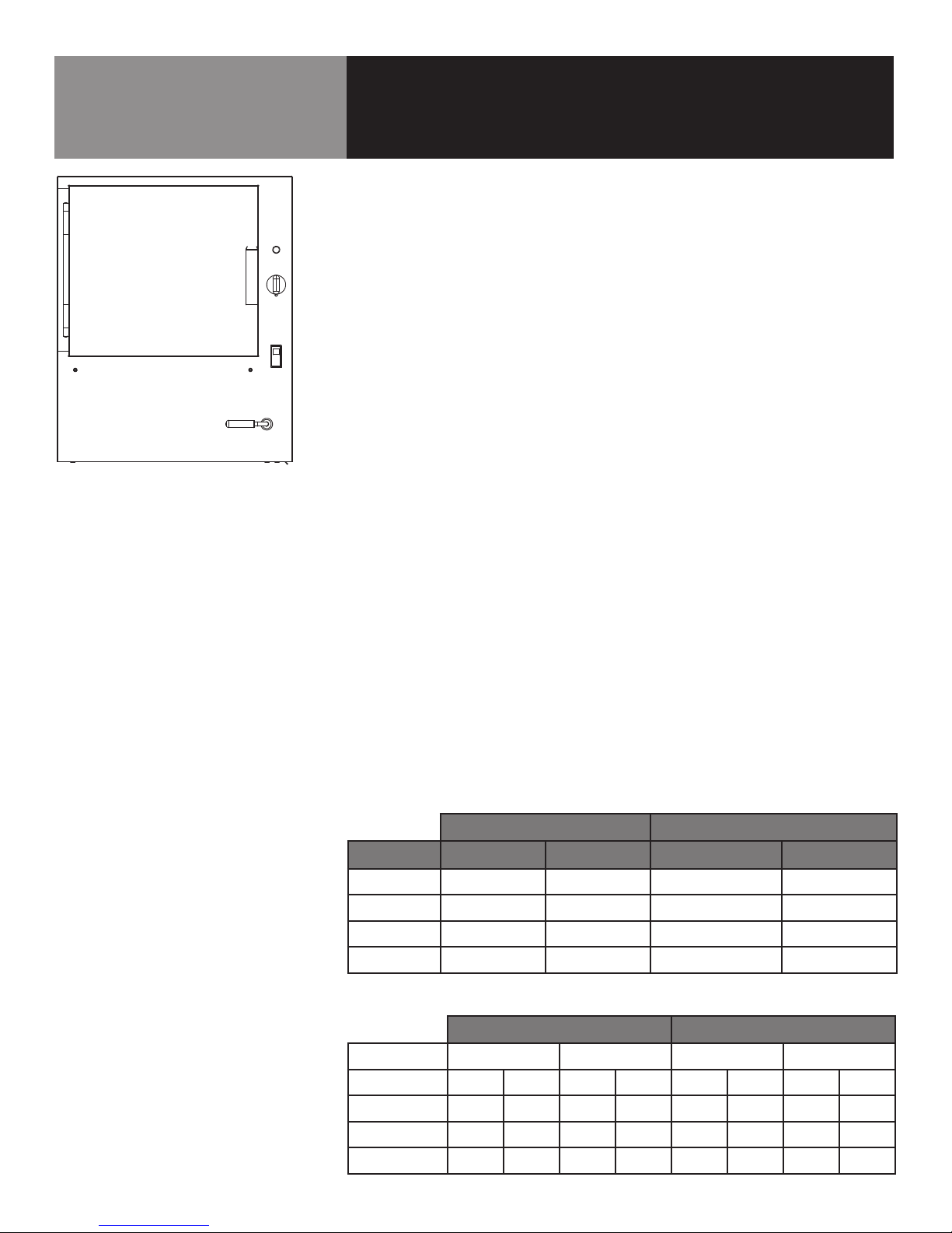
DRAIN CONNECTION
Model Drain ID Hose Size Required
ST-4E 1.5”
ST-6E 1.5”
Level the steamer left-to-right, and pitch it slightly to the front (maximum 1/4 inch) by
adjusting the optional legs or the bullet feet on the optional stand.
There must be a free air gap between the end of the drain hose and the building drain.
The free air gap should be as close as possible to the unit drain. There must also be
no other elbows or other restrictions between the unit drain and the free air gap.
Install the drain line with a constant downward pitch (see Diagram 9-1 and 9-2 at
left). IMPORTANT: Do not allow water traps in the line. A trap can cause pressure
build-up in the cooking compartment, which may cause the door gasket to leak.
For a proper drain line connection, the drain line must have a constant downward
pitch of at least 1/4” per foot. Observe local code regarding air gap spacing and drain
connections.
COUNTER-MOUNTED UNITS
This section is applicable when the steamer will be flush-mounted to a counter. All
four edges of the bottom of the steamer must be sealed with RTV silicone sealant to
the counter if optional 4 inch legs are not used. Counter must be made of a non-
combustible material such as metal or tile.
STAND STACKED UNITS
This section is only applicable if you are installing two steamers on the optional sup-
port stand. The steamers are positioned on the top and bottom shelf that are standard
with LoLo Steamer Stands.
1. Water Connections
Separate water supply connections must be provided for each unit. At each wa-
ter inlet valve a ¾” NH connection (garden hose type) is used to supply water at
the pressure and delivery rate specified on page 5 and 8.
2. Electrical Supply Connections
Separate electrical connections are required for each steamer on the stand.
NOTE: Each steamer must have its own branch circuit protection.
3. Drain Connections
Both steamers must be leveled left-to-right; and pitched to the front (maximum
of ¼”) by adjusting the bullet feet or casters on the steamer stand. Make sure
both steamer drain connections are free-venting and slope continuously to the
floor drain.
REFRIGERATED STAND MOUNTED STEAMERS
IMPORTANT: Do not mount a LoLo Steamer on a conventional undercounter refrigera-
tor. Steamers must be placed on a refrigerated equipment stand, such as the LoLo
LRES Series, which are specifically designed to support the weight of heavy cooking
equipment; and heavily insulated to resist the heat generated by a working steamer.
Installation Instructions
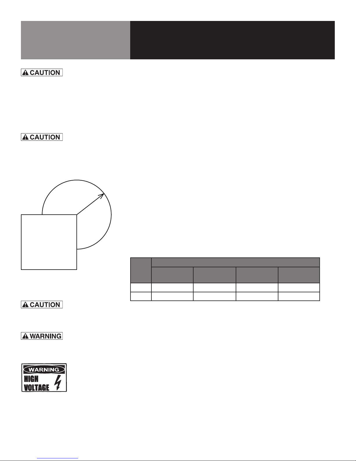
DO NOT CONNECT THE DRAIN DIRECTLY
TO A BUILDING DRAIN. BLOCKING THE DRAIN
IS HAZARDOUS.
DO NOT USE PLASTIC PIPE. DRAIN MUST BE
RATED FOR BOILING WATER.
Diagram 9-1
Improper Drain Line Connection
Diagram 9-2
DO NOT PLACE A LOLO STEAMER ON
A CONVENTIONAL UNDERCOUNTER
REFRIGERATOR. THEY ARE NOT DESIGNED
TO SUPPORT THE WEIGHT OR INSULATED
AGAINST THE HEAT PRODUCED BY THE
STEAMER. FAILURE TO USE A PURPOSE-
BUILT REFRIGERATED EQUIPMENT STAND
COULD RESULT IN REFRIGERATOR FAILURE,
UNSAFE OR SPOILED FOOD AND EVEN
MELTED PLASTIC COMPONENTS IN THE
REFRIGERATOR.