Typical examples:
On a production line you get 1 pulse for
every item. You want to count number of
items.
P.in = 1
dISP = 1
P.Set = 0
In a paper mill, you want to measure
length. You have a wheel sensor which
gives 433 pulses per metre of material.
You want to count metres to 1 decimal
place (tenths of a metre)
P.in = 433
dISP = 1.0
P.Set = 0.0
7
Scaling for the Counter modes 1 to 6
On the previous page, you saw how to select from one of 7 different modes. The first 6 modes are
all counter functions, which all have the same method of scaling.
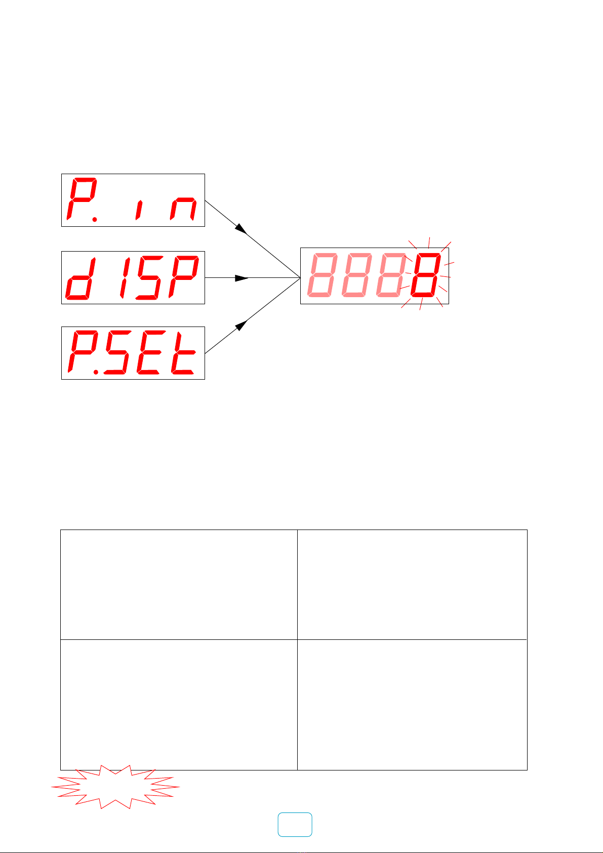
To select a mode, you pressed OK. If you selected one of the first 6 counter modes, your display
should now show:-
You’ll see one digit brighter than
the others - this means you can
change its value with the UP or
DOWN button.
Use DIGIT button to select other
digits.
Select decimal-point with the
DIGIT button if you want to change
the decimal-point position. Move
the decimal-point with UP/DOWN
buttons.
Press OK when you have set the
whole number, to move on to the
next variable
Pulses In
Display
Preset (pre-load)
The value you can set for
each of these 3 variables
You have a rotary encoder which gives
5000 pulses per rotation (360 degrees).
You want to display degrees rotation
P.in = 5000
dISP = 360
P.Set = 0
A flow sensor gives 2345 pulses per litre
You want to count milli-litres (cc). You
want the display to start from 450 ml
P.in = 2345
disp = 1000
P.Set = 450
P.Set lets you start the counter from
some value other than 0.
For example if you wanted to fit a new
counter into a system which has
already passed 1367 litres, you
would set P.Set to 1367 and the
counter would start counting from
this value.
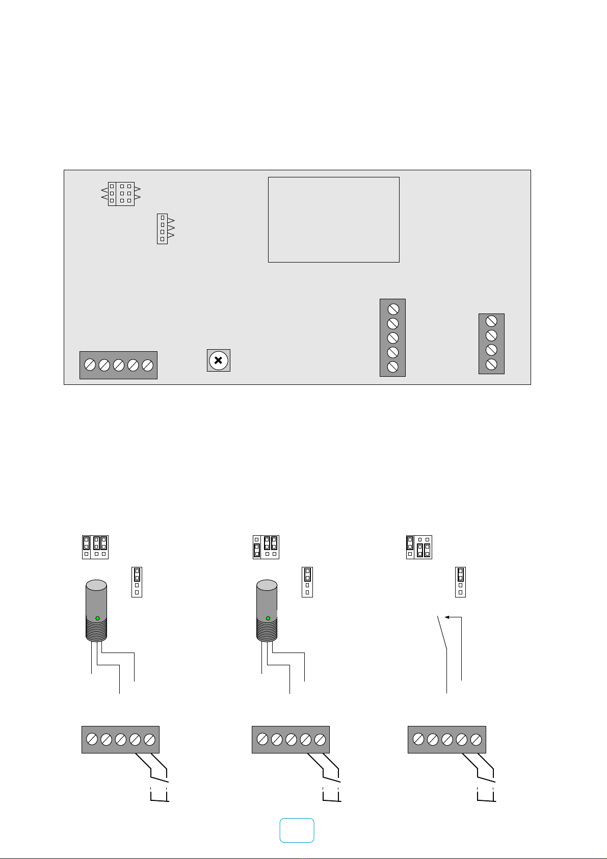
IMPORTANT To protect your settings, disconnect the
LOCKOUT link on the input connector.