London Electronics Fusion Series Installation instructions

1
Revision 25 13 March 2019
8.8.8.8.
OK
dg
Software version F04.01
Large digit process signal display
Fusion-P 4 digit version
Installation & Operating Manual
!
Caution: There is a risk of electrical
shock if this instrument is not properly installed
Caution: Risk of danger: Read the whole
manual before you install this meter
London Electronics Limited
Thorncote Road, Near Sandy, Bedfordshire SG19 1PU
Tel +44(0)1767 626444 Fax +44(0)1767 626446
www.london-electronics.com help@london-electronics.com
Easy setup
Fully scalable
24V sensor excitaition output
10 point linearisation
Optional Output 4-20mA / 0-10V isolated
Optional Alarm output = 2 or 4 relays
Optional Comms Output = RS232 or RS485
110-230V AC or 11-30V DC power
F U S I O N

2
.Warranty
We warrant our products against defects in materials or workmanship for a period of three
(3) years from the date of purchase.
In the event of a defect during the warranty period, the unit should be returned, freight (and
all duties and taxes) prepaid by the Buyer to the authorised distributor from where the unit
was purchased.
The Distributor, at its option, will repair or replace the defective unit. The unit
will be returned to the Buyer with freight charges prepaid by the distributor.
LIMITATION OF WARRANTY
The foregoing warranty shall not apply to defects resulting from:
1. Improper or inadequate maintenance by the buyer.
2. Unauthorised modification or misuse.
3. Operation outside the environmental specification of the product.
4. Mishandling or abuse.
The warranty set forth above is exclusive and no other warranty, whether written or oral is
expressed or implied. We specifically disclaim the implied warranties of merchantability
and fitness for a particular purpose.
EXCLUSIVE REMEDIES
The remedies provided herein are the buyer’s sole and exclusive remedies.
In no event shall we be liable for direct, indirect, incidental or consequential damages
(including loss of profits) whether based on contract, tort or any other legal theory.

3
Warranty 2
Warnings 4
Introduction 5
General Description 6
Suspension Mounting 7
Wall Mounting 8
Panel Mounting 9
Connections 10-11
Installation hints for best performance 12-13
48V AC power option wiring 14
Display Brightness 15
Display Calibration Modes 16
Direct Calibration 17-18
Linearisation with Direct Calibration 19-20
Theoretical Calibration 21-22
Linearisation with Theoretical Calibration 23-24
Sensor Drift correction 25
Logic Input functions 26
Logic Input connections & Front Buttons 27
Factory defaults 28
Calibration Audit number 28
Signal Filtering / Averaging (see also page 44) 29-30
Last Digit rounding 31
Scale Factor adjustment 32
Offset Adjustment 33
Menu Timeout adjustment 34
Reverse / Mirror display setting 35
Bootup Routine choices 36
Multi Memory MEM option 37
Error Codes 38
Output Options - installing 39
WEEE 40
Equipment Specifications 41
Record of Revisions 42
Declaration of Conformity 43
Separate manuals for options
Alarm option settings See Alarm manual *
Analogue output option settings See Analogue manual *
Serial output option settings See Serial manual *
Real Time Clock setting See Serial manual *
* Need a manual urgently?
You can download manuals from our website.
Contents

4
Safety First ..............Don't assume anything............. Always double check.
If in doubt, ask someone who is QUALIFIED to assist you in the subject.
Warnings
Please carefully read this manual and all warnings. Install the display ONLY when you are sure
that you’ve covered all aspects.
Where the product is intended for “UL” installations, removal or
addition of option boards is not permitted.
Check that the model number and supply voltage suit your application before
you install the display.
Connect the display according to current IEE regulations, IEC61010 &
NFPA:70 National Electric Code in USA.
Power supplies to this equipment must have anti-surge (T) fuses rated at 1A for
230V supply, 2A for 110V supply, 5A for 48VAC supply or 10A for 11-30VDC.
Don’t touch any circuitry after you have connected the display, because there may be
lethal voltages on the circuit board.
Do not apply power to the display if its case is open.
Only adjust on-board switches or connections with the power turned off
Make sure all screw terminals are tight before you switch the meter on.
Only clean the display’s case and window with a soft damp cloth. Only lightly dampen
with water. Do not use any other solvents.
!
!
!
!
!
Rear case screws - please note
The rear panel is held in place with finger-screws, which
only need to be gently tightened.
Do not use tools to tighten or loosen the screws, as
this could cause damage to the internal threads.

5
Introduction
Please contact us if you need help, if you have a complaint, or if you have suggestions to help
us improve our products or services.
If you contact us about a product you already have, please tell us the full model number and
serial number, so that we can give you accurate and fast help.
This product has a 3 year warranty. We will put right or replace any display which is faulty
because of bad workmanship or materials. This warranty does not cover damage caused by
misuse or accident.
If you return a unit for repair, please include a detailed description of the problem, and the
name of a contact who we can refer to for any questions. Please mark for the attention of the
QA Department.
IMPORTANT
If this equipment is important to your process, you may want to buy a spare to cover possible
failure or accidental damage in the future.
This is because during factory shutdown periods, you may have to to wait several weeks for
an equivalent replacement, or we may have no stock at the time you urgently need it.
You may also need to pay extra carriage charges if you want a fast, guaranteed courier service.
Warranty repairs or replacements are usually returned with a standard courier service.
We do not offer compensation for losses caused by failure of this instrument.
If you do not agree with these conditions, please return this item in unused condition, in its
original packaging and we will refund the purchase price, excluding any carriage paid.
We thought you’d prefer to know about possible delays and extra charges now, rather than
during a panic. A spare unit could help to avoid these issues.
We always try to improve our products and services, so these may change over time. You
should keep this manual safely, because future manuals, for new designs, may not describe
this product accurately.
We believe these instructions are accurate, and that we have competently designed and
manufactured the product, but please let us know if you find any errors.

6
General Description
This series of displays accepts industrial sensors to allow various physical measurements to
be made, such a weight, temperature, pressure, humidity etc. Different models are available
for different sensor types.
The main function of this series is to give a clear numeric readout of the variable being
monitored. Most models include an excitation power output, to power the sensor directly.
Various digit heights are available, to suit the maximum viewing distance required in each
installation. For every 10 metres of viewing distance required, use 1” of digit height.
Various optional output modules are also available to give alarm relay outputs, analogue
output or digital communications, or any combination of these options.
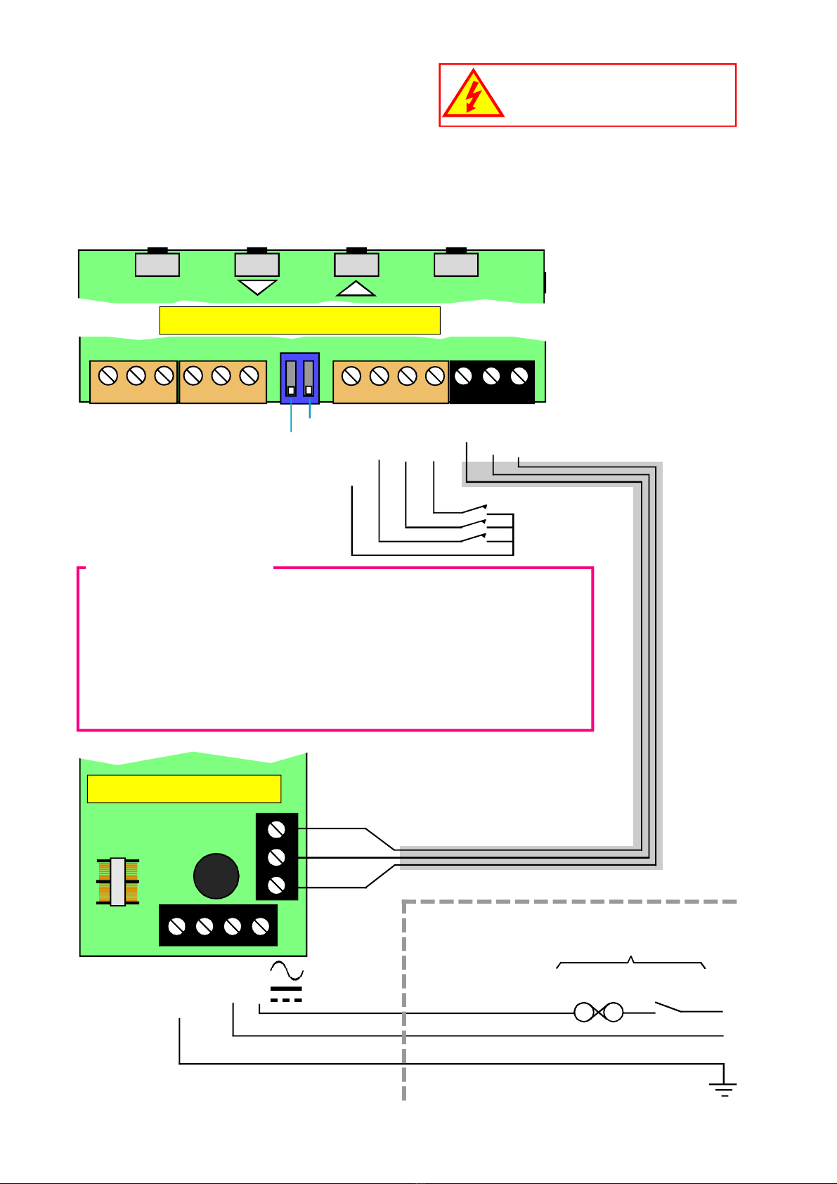
Displays are programmed using front panel pushbuttons. The front panel buttons can be
disabled. In addition, you can connect 4 remote wired pushbuttons to the display, so that you
can make adjustments while the display is mounted in an inaccessible location.
Power supply options : 100-240 VAC, 48VAC or 11-30VDC
These displays must be installed fully assembled, and must be installed according to local
electrical installation rules.
When properly installed, and provided they have been ordered with cable glands exiting the
lower surface of the case, they provide ingress protection to IP65 / NEMA4X fromall directions.
Safety
Obey all safety warnings in this manual, and install the display according to local wiring and
installation regulations. Failure to follow these guidelines may cause damage to the display,
connected equipment, or may be harmful to personnel.
Any moving mechanical device controlled by this equipment must have suitable access guards
to prevent injury to personnel if the display should fail.
!
Caution: There is a risk of electrical
shock if this display is not properly installed
Caution: Risk of danger: Read the whole
manual before you install this display

7
Suspension Mounting dimensions
Display Format X mm H mm W mm Y mm
2” 4 digit clock 231 154.5 291 247
2” 4 digit numeric 219.5 154.5 279.5 249.5
2” 6 digit clock 340 154.5 400 370
2” 6 digit numeric 316 154.5 376 346
4” 4 digit clock 393 195.5 453 423
4” 4 digit numeric 374 195.5 434 404
4” 6 digit clock 593 195.5 653 623
4” 6 digit numeric 556 195.5 616 586
6” 4 digit 520 246 580 550
6” 6 digit 760 246 820 790
8” 4 digit 690 290 750 720
8” 6 digit 1012 290 1072 1042
12” 4 digit 990 408 1050 1020
12” 6 digit 1480 408 1540 1510
16” 4 digit 1308 515 1368 1338
16” 6 digit 1960 515 2020 1990
77 mm
H mm
X mm
Plan View
Short-drop mounting holes
Long-drop mounting holes
Y mm
15mmO
6.35mmO 15mmO
6.35mmO 25mm
157.5mm
207.5mm
220mm
8.8.8.8.8.8.
OK
dg
W mm
Cable Glands. Number of glands
depends on installed options.
H mm
25mm
You can order these displays with the cable
glands in the bottom surface (as shown) the
rear, or top.
Rear glands allow you to mount the display on
top of a cubicle, using the brackets shown.
M8X12 S.S. bolt
Spring washer
Flat washer
Bracket
Rubber washer
Display boss M8 female *
Case
Detail showing bracket
hardware fitting sequence
*Do not use longer bolt threads than
12mm , or you will fracture the female boss
and the case will no longer be sealed.

8
Wall Mounting dimensions
Display Format X mm H mm W mm
2” 4 digit clock 278 154.5 291
2” 4 digit numeric 266.5 154.5 279.5
2” 6 digit clock 387 154.5 400
2” 6 digit numeric 363 154.5 376
4” 4 digit clock 440 195.5 453
4” 4 digit numeric 421 195.5 434
4” 6 digit clock 640 195.5 653
4” 6 digit numeric 603 195.5 616
6” 4 digit 567 246 580
6” 6 digit 807 246 820
8” 4 digit 737 290 750
8” 6 digit 1059 290 1072
12” 4 digit 1037 408 1050
12” 6 digit 1527 408 1540
16” 4 digit 1355 515 1368
16” 6 digit 2007 515 2020
8.8.8.8.8.8.
OK
dg
X mm
60 mm 80 mm
72.5 mm
60 mm
98 mm
60 mm
Wall
H mm
The 4 bracket holes are 5.2mm diameter
22mm
W mm
25mm
Cable Glands. Number of glands
depends on installed options.
You can order these displays with the cable
glands in the bottom surface (as shown) the
rear, or top.
Rear glands allow you to mount the display on
top of a cubicle, using the brackets shown.
M8X12 S.S. bolt
Spring washer
Flat washer
Bracket
Rubber washer
Display boss M8 female *
Case
Detail showing bracket
hardware fitting sequence
*Do not use longer bolt threads than
12mm , or you will fracture the female boss
and the case will no longer be sealed.

9
Panel mounting dimensions
8.8.8.8.8.8.
OK
dg
A mm
W mm
B mm
Neoprene
gasket
Neoprene
gasket
Bezel
H mm
Display Format H mm A mm B mm Wmm
2” 4 digit clock 172.5 154.5 291 309
2” 4 digit numeric 172.5 154.5 279.5 297.5
2” 6 digit clock 172.5 154.5 400 418
2” 6 digit numeric 172.5 154.5 376 394
4” 4 digit clock 213.5 195.5 453 471
4” 4 digit numeric 213.5 195.5 434 452
4” 6 digit clock 213.5 195.5 653 671
4” 6 digit numeric 213.5 195.5 616 634
6” 4 digit 264 246 580 598
6” 6 digit 264 246 820 838
8” 4 digit 308 290 750 768
8” 6 digit 308 290 1072 1090
12” 4 digit 426 408 1050 1068
12” 6 digit 426 408 1540 1558
16” 4 digit 533 515 1368 1386
16” 6 digit 533 515 2020 2038
M8 x 15 bolt
Spring washer
Flat washer
Wall Bracket
M8 x 20 bolt, gasket compresser
Case
Detail showing bracket hardware fitting sequence
Fit first
Fit last
Panel cutout dimensions
A+3mm(h) x B+3mm(w)
25mm
Panel
Bezel
Neoprene gasket
Cable glands
8mm
67mm

10
Connections
Alarm Lock
Calib’n Lock
Common
CC.1
CC.2
CC.3
Logic Inputs Power
Signal Input & Excitation
N L
- +
Remote
contacts
(5V DC 1mA)
Earth
1 2 3 4 5 6 7 8 9 10 11 12 13
Processor and signal input board
Power Supply board
Internal power link, installed by the factory
Fuse
Earth
- or N
+ or L
N L
- +
Earth
Fuse Switch
Customer-supplied disconnection
and overload protection devices
Circuit breaker
Power
E
Inside the enclosure Outside the enclosure
Warning:
Disconnect all power before
removing the rear of the display
There is a wide range of possible locations for the input board, output board and power
supply board/s. Their locations depend on the height of digits, number of digits, brightness of
digits and any installed options. Because the permutation of possible locations is large, we
will not describe the location of boards within the display, but simply identify the connectors
and their functions on each board, below ...
Excitation -
Signal -
mA +
V +
no connection
Excitation +
Connection Examples
A) 4-20mA direct, Term2 = -, Term3=+
B) 4-20mA 2 wire transmitter, link terminals 1&2, Term3 = -, Term6=+
C) 0-10V direct, Term2 = -, Term4 = +
D) 3 wire potentiomer (if POT option ordered) link terminals 1&2 to
low end of potentiometer, Term4 to wiper, Term6 to high end of pot
OK Digit
Processor and signal input board

11
Connections
Serial Data
output option
0, 2 or 4 Alarm Relay
output options
- +
AL4 AL3 AL2 AL1
B
A
Comm
Enable
TxD
RxD
Comm
Enable
Rated 2A 250VAC Resistive
Enable is used in mode C1
to activate or de-activate the
RS232 or RS485 serial output.
Connect to Comm to continually
transmit data.
27 26 25 24 23 22 21 20 19 18 17 16 15 14
R S 4 8 5
R S 2 3 2
Output option board (if fitted)
Analog
output
option
Button function
Remote buttons
Display’s front panel
buttons enabled/disabled
by jumper or connection
Remote programming button connector
On one of the display boards, you will find a 7 way connector, to which you can wire remote
programming buttons, to allow adjustment of the display’s settings when the display is
inaccessible.
You can also enable or disable the display’s front panel buttons, either by a remote contact
closure, or by an on-board push-on jumper switch, which is located near to the remote
button connector. When the contact is closed, or the push-on switch fitted, the front buttons
are enabled.
Connectors and options
Connectors may be
present even if output
options are not installed.
Referto rating label to see
installed options.
!
Warning:
Disconnect all power before
removing the rear of the display
Rear case screws - please note
The rear panel is held in place with finger-screws, which
only need to be gently tightened.
Do not use tools to tighten or loosen the screws, as
this could cause damage to the internal threads.
Close contact or fit jumper to
enable front panel buttons
OK
Output
Set2
Set1
Common
Common
Enable

12
Installation hints for best performance
This section offers several suggestions which will help you get the best performance from
your measurement system.
Some sensors generate comparitively small signals which can easily be corrupted by the
potentially high level of electrical noise which can be created by electrical machinery such as
motors, welding systems, discharge lighting, AC power inverters and solenoids. These steps
will ensure you get the best possible performance from your system.
1. Use good quality screened signal cable, with twisted pairs. Belden 8777NH,
Belden 9503 and AlphaWire 6010C are good choices, available from many
electrical distributors.
2. If you are using multi-pair twisted cable, each pair should be dedicated to a single
display as shown opposite, for maximum noise immunity.This will ensure that any
electrical noise induced in the cable is properly cancelled. Mixing destinations
carelessly amongst the twisted pairs can actually worsen noise performance.
3. The cable should be routed away from noisy wiring and devices such as power
feeds from inverters, discharge-lighting cables, welder cabling etc, and should
preferrably be routed in a dedicated low voltage signalling/instrumentation conduit
or cable tray.
4. Screened cable should be earthed at the display end only.
5. All wires and screens coming out of the screened cable should be kept as short
as possible to minimise pickup of noise.
6. If you are using barriers, you should earth your screen as shown below, paying
particular care that you do not earth both ends of any run of of cable.
Barriers
EARTH
Connect screen
to earth ONLY
at this end.
Connect screen
to earth ONLY
at this end.
Do not
connect
screen at
this end.
Do not
connect
screen at
this end.
Length of screened cable Length of screened cable
Sensor
Hazardous Area Safe Area
Terminal 7
on logic
input
connector
Clean Earth
Signal Input
Logic Input
Power Input
Displayconnections
Sensor connections Barrier connections

13
Display 1
Display 2
Display 3
Sensor 1
Sensor 2
Sensor 3
When using multi-core screened cable to connect several displays to several sensors, please be sure to use one twisted pair for
each display and sensor.
Do NOT use a wire from one pair for signal positive and a wire from another pair for signal negative, as this will prevent the
twisted cables form cancelling any induced electrical noise.
Displays
Sensors

14
48V AC power wiring option
~ ~
48V AC Power In
Connect Earth to

15
Set1 Set2 Output Alarms
Digit OK
Max/Min Reset
Display Brightness
You can adjust the display brightness at any time, provided the display is locked.
Lockout Switch must be ON
Press 3 seconds
Set1 Set2 Output Alarms
Digit OK
Max/Min Reset
Press for 3 seconds
Display shows briL
Each press of the UP button will select a
new brightness level.There are 7
brightness levels to choose from.
(Default = Full brightness)
Set1 Set2 Output Alarms
Digit OK
Max/Min Reset
Press to accept
1
2
3Done!
!
!Did you know, we make this display in two brightness versions?
Standard brightness for use inside, and Daylight Viewing for use outside
in direct sunlight. The Daylight Viewing version has suffix -DLV in its part
number.
OFF
Circuit board ON

16
Set1 Set2 Output Alarms
Digit OK
Max/Min Reset
Meter Calibration Modes
You can choose from two main calibration methods.
1. Direct Calibration - this is when you connect the meter to your system and
make the meter read what you want it to, at 2 different points. This is the preferred
calibration method, because it allows you to calibrate the system as a whole.
2. Theoretical Calibration - this is when you type in the sensor’s theoretical
signal level at the bottom and top of itsrange and then type in the value the
display should show, for each signal level.
How to choose a calibration method:-
Lockout Switch must be OFF
Press 3 seconds
Set1 Set2 Output Alarms
Digit OK
Max/Min Reset
Press to select dirECt or thEor
Display shows CAL then dIr
or
thEo (Default)
Set1 Set2 Output Alarms
Digit OK
Max/Min Reset
Press to accept
If you chose Theoretical, you will now be asked whether your input signal
will be DC Current or DC voltage ... the display will show Inp followed by
dC A or dC V
Set1 Set2 Output Alarms
Digit OK
Max/Min Reset
Press to select dc A or dc V
Display shows Inp then
dC A for current or
dC V for voltage (Default)
Set1 Set2 Output Alarms
Digit OK
Max/Min Reset
Press to accept
1
2
3
4
5Done!
OFF
Circuit board ON

17
Set1 Set2 Output Alarms
Digit OK
Max/Min Reset
Direct Calibration - Full Scale Setting
This is when you connect the meter to your system and make the meter read what
you want it to, at 2 different points. This is the preferred calibration method, because
it allows you to calibrate the system as a whole.
How to do direct calibration:-
If you have not done so before, please select Direct Calibration mode from
the previous page.
First we recommend you set the FULL SCALE calibration ...
Lockout Switch must be OFF
Display shows dir followed by
SE t.H
Press 3 seconds
Set1 Set2 Output Alarms
Digit OK
Max/Min Reset
Apply the highest calibration signal you
can achieve, ideally 100% of system
capacity. You can use less, but you will
get better accuracy with higher signals.
Now press OK
Set1 Set2 Output Alarms
Digit OK
Max/Min Reset
Press for 3 seconds
Set1 Set2 Output Alarms
Digit OK
Max/Min Reset
You can now set the display value you
want to see - use DIGIT to select each
digit in turn, and the UP or DOWN arrow
to increase or decrease each digit’s
value, as required.
Set1 Set2 Output Alarms
Digit OK
Max/Min Reset
Press to accept
1
2
3
4
5
Press Set2 for 3 seconds. You can now
set your decimal point position using
the UP or DOWN buttons.
Press OK when done.
Done!
OFF
Circuit board ON

18
Direct Calibration - Zero Setting
How to calibrate the ZERO point.
You can set Zero first, if you prefer, but you will not be able to change the decimal point
position in the ZERO calibration step.
This will not be an issue if your zero calibration reading is 0, but may become
confusing otherwise.
When you have finished your calibration, please remember to put the calibration
lockout switch in its ON position, to protect your settings.
OK
Max/Min Reset
Lockout Switch must be OFF
Set1 Set2 Output Alarms
Digit OK
Max/Min Reset
Apply the lowest calibration signal
you can achieve, ideally 0% of
system capacity.
Now press OK
Set1 Set2 Output Alarms
Digit OK
Max/Min Reset
You can now set the display value you
want to see - use DIGIT to select each
digit in turn, and the UP or DOWN
arrow to increase or decrease each
digit’s value, as required.
Set1 Set2 Output Alarms
Digit OK
Max/Min Reset
Press to accept
1
2
3
4
Done!
Display shows dir
followed by set.L
OFF
Circuit board ON
Set1 Set2 Output Alarms
Digit
Press 3 seconds

19
Set1 Set2 Output Alarms
Digit OK
Max/Min Reset
Linearisation with Direct Calibration
If your system is non linear, you can calibrate the meter and correct for this with the
lineariser function.
You will need to apply a series of known loads, starting at 0 and working up to full scale. You
will then tell the meter what it should read for each applied load. You can use up to 10
points.
First, you must select Direct Calibration Mode (see page on calibration Modes)
Then, proceed as shown below...
Lockout Switch must be OFF
Press together, briefly
Set1 Set2 Output Alarms
Digit OK
Max/Min Reset
If the display shows Lin.O, press Set2
button briefly so that the display shows
Lin.1, then press OK
Set1 Set2 Output Alarms
Digit OK
Max/Min Reset
1
2
3
4
Set1 Set2 Output Alarms
Digit OK
Max/Min Reset
The display will show SE. 00
Ensure no load is applied to the system
and press OK.
The display will now show rd 00
You can now tell the meter what it should
display for this load.
Select each digit in turn with the DIGIT
button, and increase or decrease each
digit’s value using the UP or DOWN
button, until the display is set as required.
Press OK when done.
The display will show Ad.Pt
Press OK
Continued ...
OFF
Circuit board ON
Display will show Lin.1 or
Lin.O (Default)

20
Set1 Set2 Output Alarms
Digit OK
Max/Min Reset
Done!
5
6
7
Set1 Set2 Output Alarms
Digit OK
Max/Min Reset
Set1 Set2 Output Alarms
Digit OK
Max/Min Reset
The display will show SE. 01
Apply your 1st known load to the system
and press OK.
The display will now show rd 01
You can now tell the meter what it should
display for this load.
Select each digit in turn with the DIGIT
button, and increase or decrease each
digit’s value using the UP or DOWN
button, until the display is set as required.
Press OK when done.
The display will show Ad.Pt
Press OK if you want to Add another
calibration point, you will repeat the previ-
ous steps, each time incrementing “Set
XX” and “rd XX” up to Set 09 and rd 09
which are the last available points.
If you want to finish adding points, press
Set2 until the display shows SAVE, and
then confirm by pressing OK
If you want to abort the setup, press Set2
until the display shows quit and then
press OK
Linearisation with Direct Calibration - cont’d.
Input
Display
Set00 Set01 Set02 Set03 Set04 Set05 Set06 Set07 Set08
rd 08
rd 07
rd 06
rd 05
rd 04
rd 03
rd 02
rd 01
rd 00
Other manuals for Fusion Series
2
This manual suits for next models
1
Table of contents
Other London Electronics Monitor manuals

London Electronics
London Electronics EasyReader ER4C User manual

London Electronics
London Electronics Fusion Series Installation instructions

London Electronics
London Electronics MAXI-INT-S Mk.2 Configuration guide

London Electronics
London Electronics EasyReader ER4S User manual

London Electronics
London Electronics EasyReader ER2C User manual

London Electronics
London Electronics Titan Series Configuration guide

London Electronics
London Electronics EasyReader ER4P User manual

London Electronics
London Electronics R175X Series User manual

London Electronics
London Electronics INTUITIVE INT4-S Installation instructions