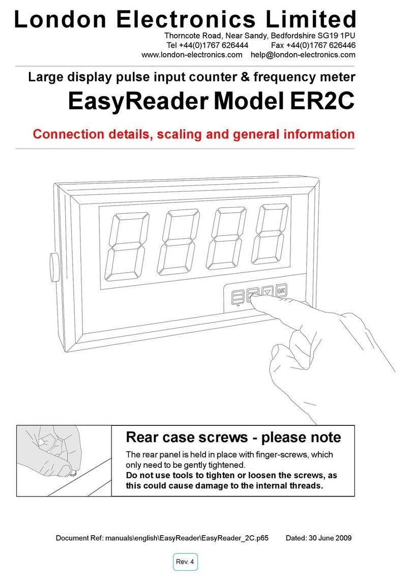
London Electronics EasyReader ER4S User manual

Document Ref:Anfield\manuals\english\ER4S Date : 30 June 2009
Rev. 2
Large display ASCII input RS232/485 remote display
EasyReader Model ER4S
Connection details, scaling and general information
Rear case screws - please note
The rear panel is held in place with finger-screws, which
only need to be gently tightened.
Do not use tools to tighten or loosen the screws, as
this could cause damage to the internal threads.
London Electronics Limited
Thorncote Road, Near Sandy, Bedfordshire SG19 1PU
Tel +44(0)1767 626444 Fax +44(0)1767 626446
www.london-electronics.com help@london-electronics.com


Alphabetic Index
Warning - read first please 2
Addresses and configuration 8
ASCII Characters 5
Baud rate 7
Before you start... 4
Brightness 3
Characters 5
Configuration of the termination character 13
Configuration of the displayed characters 12
Configuration of the rejected characters 11
Connection examples 6
Connections 6
Wiring and Jumper record sheet 20
Data descriptions 12
Declaration of Conformity 21
Description 3
Displayed characters - how to select 12
Eject unwanted characters 11
Fault finding 18
Flashing command 5
Idling mode 10
Introduction 1
Inverting the data logic 18
Language 18
List of modifications and revisions 20
Lockout connection 6
Mounting the display 15, 16
Parity 9
Peak and Valley detection 14
Position of Decimal point 14
Programme version 1,4 & 20
Rejection of unwanted characters 10
Resetting the display 14
Revisions 19
Specifications 17
String termination characters 13
Tare command 14
Termination character 13
Timeout setting 10
Index

1
-
-
-
-
Introduction
Please contact us if you need help, if you have a complaint, or if you have suggestions to help us
improve our products or services for you.
If you contact us about a product you already have, please tell us the full model number and serial
number, so that we can give you accurate and fast help.
This product has a 2 year warranty. We will put right or replace any meter which is faulty because
of bad workmanship or materials. This warranty does not cover damage caused by misuse or
accident.
IMPORTANT
If this equipment is important to your process, you may want to buy a spare to cover possible
failure or accidental damage in the future.
This is because at some times, for example during our factory shutdown periods, you may have to
to wait several weeks for an equivalent replacement. Or, we may have no stock at the time you
urgently need it.
You may also need to pay extra carriage charges if you want a fast, guaranteed courier service.
Warranty repairs or replacements are normally returned with a standard courier service.
We do not offer any compensation for losses caused by failure of this instrument.
If you do not agree with these conditions, please return this item now, in unused, clean condition, in
its original packaging and we will refund the purchase price, excluding any carriage paid.
We thought you’d prefer to know about possible delays and extra charges now, rather than during
a panic.
We always try to improve our products and services, so these may change over time. You should
keep this manual safely, because future manuals, for new designs, may not describe this product
accurately.
We believe these instructions are accurate, and that we have competently designed and
manufactured the product, but please let us know if you find any errors.

2
Safety First ..............Don't assumeanything.............Always double check.
If in doubt, ask someone who is QUALIFIED to assist you in the subject.
Warnings
Please carefully read all warnings and ONLY install the meter when you
are sure that you’ve covered all aspects.
!
* Connect the meter according to current IEE regulations and separate all
wiring according to IEC1010.
* Power supplies to this equipment must have anti-surge (T) fuses at 125mA for 230V
supply, 250mAfor 110V supply or 1Afor DC supplies in the range 11-30VDC.
* Check that the model number and supply voltage suit your application before
you install the meter.
* Don’t touch any circuitry after you have connected the meter, because there may be lethal
voltages on the circuit board.
* We designed this meter for Pollution-Degree 2 environments only. This means you must
install it in a clean, dry environment.
* Only adjust on-board switches or connections with the power turned off.
* Make sure all screw terminals are tight before you switch the meter on.
* Only clean the meter with a soft damp cloth. Only lightly dampen with water. Do not use any
other solvents.

3
Description
The EasyReader-S accepts numeric serialASCIIdata and displays it on a 4 digit LED readout. The
digits are 57mm or 102mm high, depending on model.
It can accept a limited range of alphabetic characters - limited by their ability to be represented
accurately on a 7 segment type display.
Its string extraction ability allows the display to select defined parts of a data string for display,
whilst rejecting surrounding data.
The front panel comprises of a 4 digit LED display, including decimal points and minus sign.
All adjustments are made with front panel pushbuttons.
A lockout connector allows you to disable the front panel programming buttons, to protect settings.
An unlocked display won’t perform parity checking or addressing. Every character which arrives
will be displayed as it arrives - a useful feature for diagnostic tests.
The characters may be made to flash if you include CtrlF in the datastring.
You can change the brightness of the display to one of 6 levels. To do this, press the DOWN
arrow button for more than 3 seconds and wait until the display brightness suits your environment.
The display will store the chosen brightness level, so that it will return to this brightness if power is
lost and re-applied.

Before you start ...
First, please check that the display will suit all the requirements of your application. Page 4 has
some important warnings - please check that all warnings are covered.
Next, set the switches on the back of the display to suit the data type you’ll be using. See page 6.
Remove the rear screws and slide the case apart. Connect the signal and power cables to the
appropriate screwterminalconnectors. See page 6 to checkthat you are using the correct terminals.
Apply power, and confirm that the meter illuminates all segments for a few seconds and then
shows the software version “SEr. 1.X” briefly (The X numeral depends on version).
The lockout should be OFF to allow you to change the meter’s settings - see connections page.
Set baud rate, address, parity etc. to suit your system. Now, if you send an ASCII character of the
correct baud rate, the meter should respond.
With the lockout OFF, the meter will respond immediately to each valid character received, useful
for initial diagnostics. However, to operate properly, and to safeguard your settings you must set
the lockout to ON - see connections page.
Useful free accessory
The free TERMINAL accessory in Windows is a simple and useful application you can use to
generate serial data.
It can be used to check most features of the S1861
Here’s how to connect your display to a PC’s RS232 port...
For guidance on how to set up TERMINAL, see our dedicated website help pages
http://www.london-electronics.com/terminal.htm
4
1 2 3 4 5
6 7 8 9
Interior view of a 9 pin D
connector, which you can
connect to a COM port
connector on your PC.
Signal
Common
Input Connector

5
Recognised ASCII Characters
This display is intended mainly to show numericASCII characters...
0 to 9 , hex codes 30 to 39
decimal point, hex code 2E (or 2C)
and the minus sign, hex code 2D
Some alphabetic characters can also be shown. Because 7 segment LEDs are limited in what
they can display, capital and lower case alphabetic characters will appear the same, and some
letters such as K,W and X are unrecognisable.
0 cC oO
1 dD pP
2 eE qQ
3 fF rR
4 gG sS
5 hH tT
6 iI uU
7 jJ vV
8 kK wW
9 lL xX
aA mM yY
bB nN zZ
ASCII hex code 20 to 2F (excluding 2C, 2D and 2E) inserts a space.
Two ESCAPE characters, (hex code 1B) will reset the display to its initial power-up condition.
You can FLASH the display on and off
repeatedly, if you include CTRLF (ASCII 06)
in the data string.

Use screened cables for input signal and contact closure logic functions. You can connect your
screens to the Screen Termination Point. This point connects directly to the power earth.
Install signal cables well away from noise-carrying cables and devices, to reduce the chance of
interference.
Examples of Input Signal connection for different data types ...
Connections
RS232 RS422/485 TTY 20mA Active ASR 60 Time Rx *
6
Screen
termination
point
+Power*
Data +
Data -
Common
Lockout
120 Ohm terminating
jumper.Only fit on
furthest display from
sender
or, if you have
inverted data, use....
Signal
Common
Signal A
Signal B
Common
To access the connectors, you’ll need to remove the display fromthe wall and remove the 4
screwson the rear plate.
Signal +
Common
Power +
Signal +
Signal -
Common
Locked
Unlocked
Locked
Unlocked
Locked
Unlocked
Locked
Unlocked
Common
Not used
Tare
Peak/Valley
Reset
Logic I/Ps
You can operate the Tare,
Peak/Valley and Reset functions
remotely with contact closures,
or with the front panel buttons.
To activate the front panel
buttons, you must make
permanent connections
between the desired function
connector and Common
Earth
Neutral / -
Line /+
Signal I/P
120 Ohm terminating
jumper.Only fit on
furthest display from
sender
* Power is only available on 2” display versions, to power theASR60Atomic Timecode Rx.

Baud Rate adjustment
Unlock the display - (see connections page) .
Press the BAUD button for a few seconds. The present baud rate will appear.
If you want to change the baud rate, press the up or down arrow button. Press the OK button to
save your new choice. you can choose from 300, 600, 1200, 2400, 4800 & 9600 baud.
Notes:
Lower baud rates allow longer transmission distances. Approximate limits you can expect for
RS232 are shown below...
Baud Distance max.
300 800 metres
600 400 metres
1200 200 metres
2400 100 metres
4800 50 metres
9600 25 metres
Differential data transmission modes such as RS422 ou RS485 allow longer distances and better
noise rejection. We recommend RS422 or RS485 instead of RS232, if you have that choice.
Remember to lock the display after you have finished your settings.
7

8
ADDRESS CONFIGURATION
Unlock the display - (see connections page)
Press the ADDRESS button for a few seconds. The existing address will appear on the display.
To change the address, press the up or down buttons. Press OK to save your choice.
* If you don’t need addressing, please choose Adr.- - (Adr.00 less one)
If you want to address your display, the data should be in this format:- :
<ETX><STX><ADDRESS><DATA><ETX>
<ETX> is ASCII code 03hex or 13hex (XOFF)
<STX> isASCII code 02hex or 11hex (XON)
<ADDRESS> may be a single character or 2 characters
<DATA> is the numericASCII data to be displayed.
Set the termination character to 03 if the <DATA> doesn’t include <CR>. The termination
character page tells you how to do this.
Adr.-1 to Adr-E for 1 character addressing in the range 1-E
eg. <ETX><STX><5><1234><ETX> displays 1234 on an indicator with Adr.-5.An indicator with
Adr.-0 responds to all single character addresses, and conversely, any indicator with any single
character address will display any datastring sent with address 0.
Adr.01 to Adr.EF for 2 character addressing in the range 01-EF
eg <ETX><STX><48><2468><ETX> displays 2468 on an indicator with Adr.48.
An indicator with Adr.-00 responds to all dual character addresses, and conversely, any indica-
tor with any dual character address will display any datastring sent with address 00.
PS: Character addresses A to F are the ASCII codes 3A to 3F as follows--> : ; < = > ?
Remember to lock the display after you have finished your settings.

PARITY SETTINGS
Unlock the display - (see connections page)
Press the two buttons marked “Special” until you see ‘P. no’ or ‘P. Ev.’ or P. od.’.
‘P. no’ signifies NO PARITY
‘P. Ev.’ signifies EVEN PAIRTY
‘P. od.’ signifies ODD PARITY
Use the UP or DOWN buttons to change the parity setting, to suit your needs. Press OK to save
your choice.
If there is a parity error, the display will show ‘Err.P’ , until a data string with correct parity arrives, or
until the Idle timeout occurs
9
Remember to lock the display after you have finished your settings.

Configuration TIME-OUT
You can use the Time-Out function to create a warning message if data disappears (the data line is
idle) for more than a preset time.
You can also disable this function if data will arrive occasionally, for example from an operator’s
keyboard.
After you set the Parity, and press OK, you will see ‘t.o.no’ or ‘t.o. 3’or ‘t.o.10’ or ‘t.o.30’or ‘t.o.60’
‘t.o.no’ signifies no time-out testing - the display will always show the last valid data string.
‘t.o. 3’ signifies that the display will show ------ if no valid data arrives within 3 seconds
‘t.o.10’ signifies that the display will show ------ if no valid data arrives within 10 seconds
‘t.o.30’ signifies that the display will show ------ if no valid data arrives within 30 seconds
‘t.o.60’ signifies that the display will show ------ if no valid data arrives within 60 seconds
Choose from one of these options with the UP or DOWN button. Press OK to save your choice.
The TARE and PEAK/VALLEY inputs willbe inactive during a timed-out period
Remember to lock the display after you have finished your settings.
10

EJECT data configuration
If you have a complex data string and want to display a certain part of it, you can use the ‘EJECT’
function to define how many characters to eject.
The characters which will be lost will be between the string terminator, for example <CR>, and
the data you want to display.
After the Idle setting on the previous page, the display will show ‘EJ.XX’ where XX correponds to
the number of characters to lose.
Use the UP or Down buttons to select the number of characters to eject, in the range 00 to 24.
Press OK to save your choice.
For example if your string is <STX>7768*2505_TY456<CR><ETX> and you want to display the
characters 2505, you’ll want to lose the characters _TY456 (6 characters).
So for this application you would set ‘EJ.06’
Remember to lock the display after you have finished your settings.
11

DISPLAY configuration
In the previous example, we wanted to display the value 2505.
If the characters on the left (7768* in the example) are to be ignored, we can do this by telling the
display to show only 4 characters.
Here’s how we set the number of displayable characters ...
After you set the Lose function, on the previous page, the display will show ‘dSP.3’ or ‘dSP.4’ or
‘dSP.5’ (dSP means ‘display’)
You can select either 3, 4, or 5 digits, if you press the up or down button.
In our previous example, we’d choose ‘dSP.4’
Press OK to save your choice.
The decimal point, if it appears in your data string, is not considered as a character, but the minus
or negative sign - is considered as a character. This is why we have 5 charactersavailable, to allow
negative numbers up to -1999 to be displayed
Remember to lock the display after you have finished your settings.
12

Termination Character configuration
This function is useful if the data string is complex and includes clearly identifiable characters
which you can use as a reference point for identifying wanted data characters. Perhaps the best
known termination character is the Carriage Return (identified by the codeASCII HEX 0d)
Consider the following string :
:<STX>55555_ABTOL_NETT_386.9Kg_SER02345<CR><ETX>
Let’s say you want to display 386.9 Let’s also assume that the part SER02345 can varyin length,.
You could specify the letter K as your termination character, provided it always appears in this
position relative to the data of interest.
K is represented by 4B in ASCII hex. Here’s how we would set the display to use K as the
termination character....
After the ‘Display’setting on the previous page, you will see ‘C.r. XX’ where XX corresponds to the
HEX code of the character you want to use as the termination character.
Use the UP and Down buttons to set the character’s HEX value.
(In our example of using a letter K, which is HEX 4B, this would be ‘C.r. 4b’ ).
When your setting is correct, press OK to save your choice.
Remember to lock the display after you have finished your settings.
13

Peak and Valley memory
The EasyReader-S continuously compares new incoming data with previous data and stores the
minimum and maximum values in Peak and Valley memories. You can view these values by
making a remote contact closure, or by pressing a button on the front panel of the display.
Front panel button viewing of peak and valley.
1) Connect the Peak/Valley terminal to the Common terminal - see connection page
2) Lock the display - see connection page
3) Press the UP arrow to sequentially view peak, valley and actual input values.
How to view the peak and valley with a remote contact closure
1) Lock the display - see connection page
2) Make a momentary contact closure between the Peak/Valley terminal and Common to
sequentially view peak, valley and actual input values.
Tare Command
If you want to force the display to 0, regardless of the actual incoming data value, you can do so with
the tare function. This is most often used in weighing applications.
Front panel Tare command
1) Connect the Tare terminal to the Common terminal - see connection page.
2) Lock the display - see connection page.
3) Press the front panel Tare button to tare the display to 0.
Tare command by remore contact closure
1) Lock the display -see connection page.
2) Make a momentary contact closure between the Tare terminal and Common to reset the
display to 0.
Reset Command
The reset command clears the Peak, Valley tare and latched alarm registers.
Front panel Reset command
1) Connect the Reset terminal to the Common terminal - see connection page.
2) Lock the display - see connection page.
3) Press the front panel Reset button to reset the peak/valley and tare.
Contact Closure RESET
1) Lock the display - see connection page.
2) Make a momentary contact closure between the Reset terminal and Common to reset the
peak/valley and tare.
14

13
How to Mount your display
Wall mount your EasyReader displayin a clean, dry environment.
Drill 4 holes in your wall, spaced as you see in this diagram...
The mounting screws you use should have a diameter between 3.4 and 4.6 mmand should
be suitable for the material of the wall. You may need to use wall plugs or other screw
accessories, if the wall material is not suitable to take screws directly.
Route cables neatly away fromthe display. If the cables may become damaged in the
environment, protect them with suitable conduit or trunking.
407 mm
Place the brackets as shown, so that the display covers
the 4 mounting screws
365 mm
The 4 bracket holes are all 5mm diameter
Fit the brackets to the wall.
Then, fit the display between the brackets.
1. Wall Mounting
M8 Spring Washer
M8 Plain Washer
25mm rubber washer
M8 Pan Screw
Wall bracket
25.0 mm
47.5 mm
2.5mm
Side View
Wall

14
How to Mount your display ... continued
1. Suspension Mounting
Suspension mount your EasyReader display in a clean, dry environment.
The mounting screws you use should have a diameter between 3.2 and 3.8 mmand should
be suitable for the supporting material. You may need to use screw plugs or other screw
accessories, if the material is not suitable to take screws directly.
Mount the bracket first, then fit the display to the bracket. There are 2 holes on each
bracket you can use to mount the bracket to its support.
Route cables neatly away fromthe display. If the cables may become damaged in the
environment, protect them with suitable conduit or trunking.
M8 Spring Washer
M8 Plain Washer
25mm rubber washer
M8 Pan Screw
25.0 mm
14

Specifications
ASCII data input Choice of RS422, RS485, RS232 or 20mA TTY passive and
active. Numeric in the range -1999 to 9999
Baud rates Choice of 300, 600, 1200, 2400, 4800, or 9600
Data makeup 7 data bits, with parity or 8 bits without parity
1 start bit, 1 or more stop bits.
Parity Selectable - none, even or odd
Addresses Selectable a. Unaddressed
b. Single character 0 to F
c. 2 characters 00 to FF
Display update rate 1 update per datastring received
Idle timeout Can be set not to timeout, or to show ------ after 3, 10 ,30 or 60 sec
onds without valid data arriving.
Termination character Normally set for <CR> (Hex 13) but can be set for any
HEXASCIIvalue
Programme memory EEPROM non volatile memory, 10 year storage. No batteries.
Dimensions 95mm high by 240 mm wide on 57mm digit version
95mm high by 240 mm wide on 102mm digit version
Case depth 75 mm
Weight 57 mm digit version :- 1500 gramms typically
102 mm digit version :- 2500 gramms typically
Case material PVCu black
Connectors Detachable screw terminal types, within the enclosure
Cables enter the case via compression glands
Temperature Storage -20 to +70, operating 0 to +50 °C
Power 95-265 VAC or 11-30 VDC to special order.
Consumption 8 Watts maximum
17
Table of contents
Other London Electronics Monitor manuals

London Electronics
London Electronics EasyReader ER4C User manual

London Electronics
London Electronics INTUITIVE INT4-S Installation instructions

London Electronics
London Electronics Fusion Series Installation instructions

London Electronics
London Electronics R175X Series User manual

London Electronics
London Electronics EasyReader ER4P User manual

London Electronics
London Electronics EasyReader ER2C User manual

London Electronics
London Electronics Titan Series Configuration guide

London Electronics
London Electronics Fusion Series Installation instructions

London Electronics
London Electronics MAXI-INT-S Mk.2 Configuration guide