LONGI LR6-60-M Series User manual

Installation Manual for
LONGi Solar PV Modules
V15

Safety Note
01
• This manual elaborates on installation and safety use information for PV power gener-
ating modules (hereinafter referred to as module) of LONGi Solar Technology Co., Ltd.
(hereinafter referred to as LONGi). Please abide by all safety precautions in this guide
and local regulations.
• Installation of modules requires professional skills and knowledge and is to be carried
out by qualified personnel. Please read this manual carefully before installing and using
this module. Installation personnel shall get familiar with mechanical and electrical
requirements of this system. Please keep this manual properly as reference for future
maintenance or upkeep or for sales and treatment of modules.
• If you have any doubts, please contact LONGi customer service personnel for further
interpretation.
Applicable Module Type Status
Module
Structure
Monofacial
Module
LR6-60-***M LR6-72-***M IEC、UL single glass
LR6-60BK-***M LR6-72BK-***M IEC、UL single glass
LR6-60HV-***M LR6-72HV-***M IEC、UL single glass
LR6-60PB-***M LR6-72PB-***M IEC、UL single glass
LR6-60PE-***M LR6-72PE-***M IEC、UL single glass
LR6-60PH-***M LR6-72PH-***M IEC、UL single glass
LR6-60MP-***M LR6-72MP-***M IEC single glass
LR6-60MPH-***M LR6-72MPH-***M IEC single glass
LR6-60HPH-***M LR6-72HPH-***M IEC、UL single glass
LR6-60HPH-***MC LR6-72HPH-***MC IEC、UL single glass
LR6-60HPB-***M / IEC、UL single glass
LR6-60OPH-***M LR6-72OPH-***M IEC single glass
LR6-60DG-***M LR6-72DG-***M IEC、UL double glass
LR6-60PD-***M LR6-72PD-***M IEC、UL double glass
LR6-60HPD-***M LR6-72HPD-***M IEC、UL double glass
LR6-60HIH-***M LR6-72HIH-***M IEC、UL single glass
LR6-60HIB-***M / IEC、UL single glass
LR4-50HPH-***M / IEC、UL single glass
LR4-60HPH-***M LR4-72HPH-***M IEC、UL single glass
LR4-60HPB-***M / IEC、UL single glass
LR4-60HIH-***M LR4-72HIH-***M IEC、UL single glass
LR4-60HIB-***M / IEC、UL single glass
LR4-66HPH-***M / IEC、UL single glass
LR4-66HP-***M / IEC、UL single glass
LR4-66HIH-***M / IEC、UL single glass
LR5-54HPH-***M / IEC、UL single glass
LR5-54HPB-***M / IEC、UL single glass
LR5-54HIH-***M / IEC、UL single glass
LR5-54HIB-***M / IEC、UL single glass
LR5-54HNB-***M / IEC、UL single glass
LR5-54HTH-***M /IEC、UL single glass
LR5-54HTB-***M /IEC、UL single glass
LR5-66HPH-***M LR5-72HPH-***M IEC、UL single glass
LR5-66HIH-***M LR5-72HIH-***M IEC、UL single glass
/ LR5-72HTH-***M IEC、UL single glass
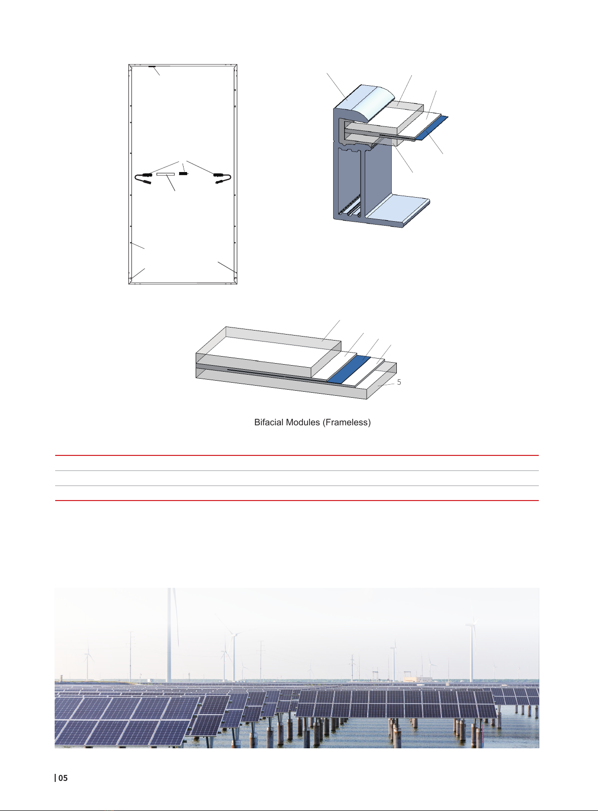
Bifacial
Module
LR6-60BP-***M LR6-72BP-***M IEC、UL double glass
LR6-60HBD-***M LR6-72HBD-***M IEC、UL double glass
LR6-60HBD-***MC LR6-72HBD-***MC IEC、UL double glass
/ LR6-78HBD-***M IEC、UL double glass
LR6-60OPD-***M LR6-72OPD-***M IEC double glass
LR6-60HIBD-***M LR6-72HIBD-***M IEC、UL double glass
LR4-60HBD-***M LR4-72HBD-***M IEC、UL double glass
LR4-60HIBD-***M LR4-72HIBD-***M IEC、UL double glass
LR5-66HBD-***M LR5-72HBD-***M IEC、UL double glass
LR5-66HIBD-***M LR5-72HIBD-***M IEC、UL double glass
/ LR5-72HND-***M IEC、UL double glass
/ LR5-72HTD-***M IEC、UL double glass

Contents
1 / Introduction
2 / Laws and Regulation
3 / General Information
4 / Installation Conditions
4.1 Installation Site and Working Environment
4.2 Selection of Tilt Angles
5 / Mechanical Installation
6 / Electrical installation
7 / Grounding
8 / Operation and maintenance
3
3
4
4
6
8
9
9
10
11
11
12
13
13
13
14
14
15
18
18
19
20
24
24
24
25
25
25
26
27
27
28
28
28
02
3.1 Modules Identification
3.2 Junction box style and wiring method
3.3 Regular Safety
3.4 Electrical Performance Safety
3.5 Operation Safety
3.6 Fire Safety
5.1 Regular Requirements
5.2 Monofacial assembly mechanical installation
5.2.1 Bolts Mounting
5.2.2 Clamp Mounting
5.2.3 Installation and Mechanical Load of Monofacial Module
5.3 Bifacial module Mechanical Installation
5.3.1 Bolts Mounting
5.3.2 Clamps Installation
5.3.3 Installation and Mechanical Load of Bifacial Module
6.1 Electrical Performance
6.2 Cables and Wiring
6.3 Connector
6.4 Bypass diode
6.5 PID Protection and Inverter Compatibility
8.1 Cleaning
8.2 Module Appearance Inspection
8.3 Inspection of Connectors and Cables
9 Release and execution

1
Electrical and mechanical installation information will be introduced in this installation manual, so please read and under-
stand the information before installing LONGi modules. In addition, this manual also contains some safety information that
you shall be familiar with. All contents in this manual are intellectual properties of LONGi which originates from long term of
technical exploration and experience accumulation of LONGi.
This installation manual does not entail any explicit or implicit quality warranty and does not stipulate on compensation
schemes for losses, module damages or other costs caused by or related to module installation, operation, utilization and
maintenance process. LONGi will not take any responsibility if patent rights or the third party rights are infringed by use of
modules. LONGi reserves the rights for modifying product manual or installation manual without noticing in advance. It is
recommended to visit our website regularly at www.longi.com for the latest version of this installation manual.
If customers fail to install modules as per requirements set forth in this manual, the limited warranty provided for customers
will be invalid. In addition, suggestions in this manual are to improve safety of module installation, which are tested and
proved by practices. Please provide this manual to PV system users for reference and inform the advises on operation,
maintenance requirements etc.
2
Introduction
Laws and Regulation
The mechanical and electrical installation of photovoltaic modules shall be in accordance with applicable regula-
tions, including electrical law, construction law and electrical connection requirements. These regulations vary
from sites to sites, for example, building roof installation, vehicle applications, etc. Requirements may also vary
depending on the installed system voltage, DC or AC. Please contact local authorities for specific terms.
03

3General Information
3.1 Modules identification
Three labels on the module contain the information below:
1. Nameplate: product type, rated power, rated current, rated voltage, open circuit voltage, short circuit current under testing
conditions, certification indicator, maximum system voltage, etc.
2. Current classification label: Rated working current.(H indicates High, M indicates Medium, L indicates Low)
3. Serial Number label: A unique serial number which is laminated inside the module permanently which can be found in the
front of the module. There is another same serial number beside the module nameplate.
6
1234
5
04
Figure 1 Typical Mechanical Drawing of Mono-facial Modules
(Please refer to section 3.2 for the location of the junction box. The specific version is subject to the corresponding specification.)
1
Frame 2 Glass 3 EVA 4 Solar Cell
5 Backsheet 6 Silica Gel 7 Junction Box 8 Name Plate
9 Cable 10 Connector 11 Mounting Hole 12 Grounding Hole
13 Drain Hole 14 Bar Code
12
7
10 10
8
99
14
13
11

Bifacial Modules (With Frame)
Bifacial Modules (Frameless)
2
34
3
5
12
3
4
5
05
Figure 2 Typical Modules Mechanical Drawing
(Please refer to section 3.2 for the location of the junction box. The specific version is subject to the corresponding specification.)
10
9
7
8
12
11
1
Frame 2 Front Glass 3 EVA
/
POE 4 Solar Cell
5 Back Glass 6 Sealant 7 Junction Box 8 Name Plate
9 Mounting Holes 10 Grounding Holes 11 Drain Holes 12 Bar Code

06
3.2 Junction box style and wiring method
Junction Box Location Icon Recommended Wiring Method
Vertical Installation: Standard Cable Length
(Note:One end of the single row needs to be extended.
Horizontal Installation: Standard Cable Length
Vertical Installation: Standard Cable Length
(Note: One end of the single row needs to be extended.)
Horizontal Installation:60 type PV module cable length ≥1.2m, 72 type PV
module cable length ≥1.4m

07
Junction Box Location Icon Recommended Wiring Method
Vertical Installation: Standard Cable length:
Note:The extra extended cable is required for connection at the turn-back
corner of wiring as shown below.
Horizontal Installation:
60 type PV module cable length ≥1.2m, 72 type PV module cable length
≥1.4m, 78 type PV module cable length ≥1.5m
Vertical Installation:
Method 1: Standard cable length Method 2: Single component cable
length ≥1.2m
Horizontal Installation:Standard cable length

08
The application level of LONGi Solar module is Class Ⅱ, which can be used in systems operating at > 50 V DC or >240
W, where general contact access is anticipated;
When the modules are for rooftop application, it is necessary to take the overall fire rating of the finished structure as well
as operation and maintenance into account. The roofing PV system shall be installed after being evaluated by construc-
tion experts or engineers and with official analysis results for the entire structure. It shall be proved capable of supporting
extra weight of system racking structures and PV modules.
For your safety, please do not work on the roof without PPE(Personal Protective Equipment) which include but not limited
3.3 Regular Safety
Figure 3 Junction Box Style and Wiring Method
to fall protection, ladder or stair and personal protective measures.
For your safety, please do not install or handle modules in unsafe conditions including but not limited to strong wind or
gust, damp or sandy roofs.
Junction Box Location Icon Recommended Wiring Method
Vertical installation:
Method 1: Standard cable length Method 2: Single component cable
length ≥1.2m
Horizontal Installation: Standard cable length

The application level of LONGi Solar module is Class Ⅱ, which can be used in systems operating at > 50 V DC or >240
W, where general contact access is anticipated;
When the modules are for rooftop application, it is necessary to take the overall fire rating of the finished structure as well
as operation and maintenance into account. The roofing PV system shall be installed after being evaluated by construc-
tion experts or engineers and with official analysis results for the entire structure. It shall be proved capable of supporting
extra weight of system racking structures and PV modules.
For your safety, please do not work on the roof without PPE(Personal Protective Equipment) which include but not limited
09
PV modules can produce DC current under sunlight. Any contact of exposed metal at module's wiring parts may result in
electrical shock or burn. Any contact of 30V or larger DC Voltage can be fatal.
In case of no connected load or external circuits, modules can still produce voltage. Please use insulation tools and wear
rubber gloves when operating modules in the sunlight.
No switch is on the PV modules. Operating of PV modules can only be stopped when they are kept from sunlight or covered by
hard board or UV-proof materials or when the angle of the modules facing sun are placed on smooth and flat surfaces.
To avoid electric arc or electric shock hazards, please do not break down electric connection in loaded conditions. Incorrect
connections will also lead to electric arc or shock. Keep connectors dry and clean and make sure that they are in good
operating condition. Do not insert other metals into the connectors or carry out electric connection by whatever means.
Snow, water or other reflective medium in surrounding environments that intensify light re-flection will increase output current
and power. And module voltage and power will increase under low temperature condition.
If module glass or other sealing materials are damaged, please wear PPE(personal protective equipment) and then isolate
modules from the circuit.
Do not operate when modules are wet unless you wear PPE(personal protective equipment). Please follow the cleaning
requirements in this manual when cleaning modules.
Do not contact connectors with the following chemicals: Gasoline, White Flower oil , woodlock oil, Mold temperature oil, Engine
oil (such as KV46), Grease(such as Molykote EM-50L), Lubricating oil, Rust-proof oil, Stamping oil, Diesel, Cooking oil,
Acetone, alcohol, essential balm, Bone-setting liquid, Banana oil, release agent(such as Pelicoat S-6), adhesive and potting
materials capable of generating oxime gas(such as KE200、CX-200、chemlok), TBP, cleaning agent etc.
3.4 Electrical Performance Safety
3.5 Operation Safety
to fall protection, ladder or stair and personal protective measures.
For your safety, please do not install or handle modules in unsafe conditions including but not limited to strong wind or
gust, damp or sandy roofs.

10
Please refer to local laws and regulations before installing modules and abide by requirements on building fire protection.
According to the corresponding certification standards, the fire rating of LONGi Mono-facial modules is UL type 1or2 or
IEC Class C, the fire rating of LONGi bifacial modules is UL type 29 or IEC Class C.
The roof should be coated by a layer of fireproof materials with suitable fire protection rating for roofing installation and
make sure that the back sheet and the mounting surface are fully ventilated.
Different roof structures and installation modes will affect fireproof performance of buildings. Improper installation may
lead to the risk of fire.
To guarantee roof fire rating, the distance between module frame and roof surface must be ≥10cm. (0.39 inch)
Adopt proper module accessories such as fuse, circuit breaker and grounding connector according to local regulations.
Please do not apply modules in where exposed inflammable gases are nearby.
3.6 Fire Safety
• Open modules outer package when installation.
• Do not damage the package and do not drop packaged modules on the ground.
• Do not exceed the indicated maximum layer limit on the packaging carton when piling
modules up.
• Put packaging carton in the ventilated, water-proof and dry places before unpacking
modules.
• Follow unpacking instructions when Opening packaging carton.
• Carrying modules with the junction box or wires are strictly forbidden.
• Do not stand or walk on modules.
• To avoid glass to be damaged, heavy objects are not allowed on modules.
• Be careful when placing modules at corners in particular.
• Do not try to dismantle the module or remove nameplate or parts of modules.
• Do not paint or apply any other adhesive on modules.
• Do not damage or scratch backsheet of modules.
• Do not drill holes on the frame of module, which may reduce frame loading capacity and
lead to frame corrosion and invalidation of the limited warranty provided for customers
• Do not scratch anodic coating of aluminum alloy frame except for grounding connection.
Scratch may lead to frame corrosion and reduce frame loading capacity and long-term
reliability.
• Do not repair problematic modules on your own.

4Installation Conditions
11
4.1 Installation Site and Working Environment
• The modules cannot be used in space
• Do not manually focus sunlight with mirrors or magnifying glass onto modules.
• LONGi modules shall be installed on proper buildings or other appropriate places (such as ground, garage, building outer
wall, roof, PV tracking system) but shall not be installed on any vehicles.
• Do not install modules at places that are possible to be flooded.
• LONGi suggests that modules be installed in the working environment with the temperature of -40℃to 40℃of which is
the monthly average highest and lowest temperature of the installation sites. The extreme working environment
temperature for modules is -40℃to 85℃.
• Make sure that installed modules do not suffer wind or snow pressure that exceeds the permissible maximum load limit.
• Modules shall be installed in places free from shadows throughout the year. Make sure there are no light-blocking
obstacles in the installation sites.
• Carry out lightning protection for modules installed in places with frequent lightning and thunder.
• Do not install modules in places with possible inflammable gases.
• Modules cannot be used in environments with too much hails, snows, flue gas, air pollution and soot or in places with
strong corrosive substances such as salt, salt mist, saline, active chemical steam, acid rain, or other substances
corroding modules, affecting modules’ safety or performance.
• Please take protective measures to ensure reliable and safe installation of modules in severe environments such as
heavy snow, cold and strong wind or islands close to water and salt mist or deserts.
• LONGi modules passed the IEC61701 salt spray corrosion test, but the corrosion may still occur on where the modules
frame is connected to the bracket or where the grounding is connected. In case LONGi modules are installed ≥50m away
from the ocean side, and related parts and components should be protected with anti-corrosion measures.

12
Module
Tilt Angle
Sun Light
4.2 Selection of Tilt Angles
Tilt angle of PV modules refer to the included angle between module surface and horizontal ground. The module will
obtain the maximum power output when directly facing the sunlight.
Modules are preferred to be south-facing in the north hemisphere and north-facing in the south hemisphere.
Please refer to standard modules installation guideline or suggestions from experienced PV module installer, for the
specific installation angle.
LONGi suggests that tilt angle of module installation be no less than 10°, so module surface dust can be washed away
easily by rainfall and frequency of cleaning can be reduced. And it is easy for accumulated water to flow away physically
and avoid water mark on the glass surface which may further affect module appearance and performance.
LONGi modules connected in string should be installed with the same orientation and tilt angle. Different module orienta-
tion and tilt angle may result in different levels of solar irradiation and also power generation. In order to achieve the
maximum annual generating capacity, the optimal orientation and inclination of PV modules in the installed area should
be selected to ensure that sunlight can still reach to modules even on the shortest day of the year.
If LONGi modules are used in off-grid System, the tilt angle should be calculated based on seasons and irradiation to
maximize the output power. If the modules output power meets the acquired load under the period of the worst irradiation
in the year, the modules should be able to meet the load of the whole year. If the LONGi modules are used in grid-con-
nected system, the tilt angle should be calculated based on the principle to maximize the yearly output power.

5Mechanical Installation
13
5.2 Monofacial assembly mechanical installation
Module and bracket system connection
can be realized by mounting holes,
clamps or embedded systems. Installa-
tion shall follow the demonstration and
suggestions below. If installation mode
is different, please consult LONGi
customer service personnel and obtain
approval. Otherwise, modules may be
damaged and limited warranty will be
invalid.
5.1 Regular Requirements
• Make sure that installation method and mounting structure are solid enough to meet the expected load-bearing
requirement, which is requisite assurance from PV system installer. Installation bracket system shall be tested and
inspected by the third party testing institution with static mechanical analysis capacity in accordance with local national
standards or international standards.
• Mounting structure shall be made from durable, corrosion resistant, UV-proof materials.
• Modules shall be fixed on the bracket solidly.
• In regions with heavy snowfall in winter, adjust the height of the mounting system so that the lower edge of the
module is not covered by snow. In addition, ensure the lower part of module is not in the shadow of plants, trees or
damaged by flying sand and stone.
• If modules are installed on brackets parallel to the roof or wall, the minimum gap between the module frame and the
roof/wall shall be 10cm which is good for air circulation to achieve better performance of module. Make sure the building
is suitable for installation before installing modules on roof. Moreover, seal properly to prevent leakage.
• The module frames can appear thermal expansion and cold contraction. So the minimum distance between two
adjoining modules shall be no less than 10 mm (0.39 inch).
• Make sure that backsheet of modules will not be in contact with bracket or building structures that can pierce into the
inside of the modules, especially when the module surface is imposed by pressure.
• Maximum static load of the PV module is downforce 5400pa and uplift force 2400pa, which can vary from different
mounting methods of the modules (please refer to the following installation guidance), the described load in this manual
is for the test load.
• Note: on the basis of IEC61215 - 2016 installation requirements, when computing the corresponding maximum design
load, a safety factor of 1.5 need to be considered in compliance with the local laws or regulations.
• Modules can be installed horizontally or vertically. When installing the components, be cautious not to block the drain
hole of the frame.

Recommended accessories are as below :
Figure4 Bolt Installation of Mono-facial Modules
14
5.2.1 Bolts Mounting
LONGi modules come standard with 8 mounting holes matching M8 bolts (marked by the blue dashed box in the figure
below, according to the location distribution hereinafter referred to as inner four holes and outer four holes); 72 type and
some 66 type modules have additional 4 mounting holes matching M6 bolts (marked by the red circle in the figure below,
400mm holes for short), which are used for matching with the tracking bracket system products from manufacturers such
as NEXTracker. Apply bolts to fix modules on the bracket through mounting holes on the back-side frame. See details in
Figure 4.
Suggestion :(1)M8 bolt tightening torque range: 12-16 N•m; M6 bolt tightening torque range: 8-12 N•m;
(2) When using LONGi 30mm (30H) height frame module, it is recommended to select L ≤ 20mm length
fasteners. (If there is a special model, consult LONGi customer service personnel);
5.2.2 Clamp Mounting
The module can be mounted by a dedicated clamp, as shown in Figure 5.
Under no circumstances should the clamp touch the glass or deform the frame. The interface of the clamp to the front of
the frame must be smooth and flat to prevent frame or other components from being damaged.
Make sure that these has no shadow caused by clamps.
The drain holes of module cannot be blocked by clamps.
For framed PV module,the clamp must maintain an overlap of 8-11 mm with the frame of the module (you can change
the cross section of the clamp if the module is securely installed). For frameless PV module,the clamp must maintain an
overlap of 15 mm at maximum with the module. The applied value of torque should refer to mechanical design standard
and the bolt type customer is using, for example: M8: 14-18 N•m.
400mm
8 installation holes
(4 inner, 4 outer)
Use M8 bolts
4 400mm-span
installation holes
Use M6 bolts
Bolt
Washer
Washer
Aluminum frame
Bracket
Spring washer
Nut
Accessories Model Material Note
Bolt M8 (full thread
recommended)
M6 (full thread
recommended) Q235B/SUS304 Accessories
material selection
should be based
on application
environment.
Washer
2pcs, thickness
≥1.5mm and outside
diameters=16mm
2pcs, thickness ≥1.5mm
and outside diameters
=12-16mm
Q235B/SUS304
Spring Washer 8 6 Q235B/SUS304
Nut M8 M6 Q235B/SUS304

Figure 6 Monofacial Module Installation Annex
15
Figure 5 Clamp Installation of Monofacial Module
bolt
bolt
laminated part
laminated part
aluminum frame aluminum
frame
bracket bracket
washer
washer
washer
spring washer
clamp
clamp
washer
spring washer
nut
nut
5.2.3 Installation and Mechanical Load of Monofacial Module
Mono-facial modules can be mounted by bolts or clamps. The mounting method and maximum test load are shown as
follow (The unit of distance and length in the table below is millimeter (mm), and the unit of pressure is Pascal (pa)).
Installation with bolts into 4 outer holes
Beam perpendicular to long sides
Installation with bolts into 4 inner holes
Beam perpendicular to long sides
(clamp length≥50mm)
Beam perpendicular to short sides
(clamp length≥50mm)
on long sides
(clamp length=150mm)
Clamps are mounted at the corners of short frame.
(clamp length ≥60mm, the overlap of clamp and
frame≥9mm)

The maximum test load of framed mono-facial modules:
16
Installation
Method
Module Type
Bolts Mounting Clamps Mounting
Mounting rails cross the
long frame Mounting rails cross the long frame Mounting
rails cross the
short frame
Clamps are
mounted at
the corners
of short
frame
Outer Four-
hole
Inner Four-
hole
1/4L-50≤D
≤ 1/4L+50
250≦D
≦ 350
300≤D
≤ 400
350≤D
≤ 450
400≤D
≤ 500
150≤E
≤ 250
50/54/60/66-cell Framed Mono-facial Modules
LR6-60-***M ±2400 +5400,
-2400 +5400,
-2400 / / / / ±2400 /
LR6-60HV-***M ±2400 +5400,
-2400 +5400,
-2400 / / / / ±2400 /
LR6-60BK-***M ±2400 +5400,
-2400 +5400,
-2400 / / / / ±2400 /
LR6-60PE-***M ±2400 +5400,
-2400 +5400,
-2400 / / / / ±2400 /
LR6-60PH-***M ±2400 +5400,
-2400 +5400,
-2400 / / / / ±2400 /
LR6-60PB-***M ±2400 +5400,
-2400 +5400,
-2400 / / / / ±2400 /
LR6-60MP-***M ±2400 +5400,
-2400 +5400,
-2400 / / / / ±2400 /
LR6-60MPH-***M ±2400 +5400,
-2400 +5400,
-2400 / / / / ±2400 /
LR6-60HPH-***M ±2400 +5400,
-2400 +5400,
-2400 / / / / ±2400 /
LR6-60HPH-***MC ±2400 +5400,
-2400 +5400,
-2400 / / / / ±2400 /
LR6-60HPB-***M ±2400 +5400,
-2400 +5400,
-2400 / / / / ±2400 /
LR6-60HIH-***M ±2400 +5400,
-2400 +5400,
-2400 / / / / ±2400 /
LR6-60HIB-***M ±2400 +5400,
-2400 +5400,
-2400 / / / / ±2400 /
LR6-60DG-***M ±2400 +5400,
-2400 +5400,
-2400 / / / / ±2400 /
LR6-60PD-***M ±2400 +5400,
-2400 +5400,
-2400 / / / / ±2400 /
LR6-60HPD-***M ±2400 +5400,
-2400 +5400,
-2400 / / / / ±2400 /
LR6-60OPH-***M +5400,
-2400 ±2400 / / +5400,
-2400 / / ±2400 /
LR4-50HPH-***M ±2400 +5400,
-2400 +5400,
-2400 / / / / ±2400 /
LR4-60HPH-***M ±2400 +5400,
-2400 +5400,
-2400 / / / / ±2400 /
LR4-60HPB-***M ±2400 +5400,
-2400 +5400,
-2400 / / / / ±2400 /
LR4-60HIH-***M ±2400 +5400,
-2400 +5400,
-2400 / / / / ±2400 /
LR4-60HIB-***M ±2400 +5400,
-2400 +5400,
-2400 / / / / ±2400 /
LR4-66HP-***M +5400,
-2400 ±2400 / / / +5400,
-2400 / ±2400 /
LR4-66HPH-***M +5400,
-2400 ±2400 / / / +5400,
-2400 / ±2400 /
LR4-66HIH-***M +5400,
-2400 ±2400 / / / +5400,
-2400 / ±2400 /
LR5-54HPH-***M ±2400 +5400,
-2400 / +5400,
-2400 / / / ±2400 +2400/-1800
LR5-54HPB-***M ±2400 +5400,
-2400 / +5400,
-2400 / / / ±2400 +2400/-1800
LR5-54HIH-***M ±2400 +5400,
-2400 / +5400,
-2400 / / / ±2400 +2400/-1800
LR5-54HIB-***M ±2400 +5400,
-2400 / +5400,
-2400 / / / ±2400 +2400/-1800
LR5-54HNB-***M ±2400 +5400,
-2400 / +5400,
-2400 / / / ±2400 +2400/-1800
LR5-54HTH-***M ±2400 +5400,
-2400 / +5400,
-2400 / / / ±2400 +2400/-1800
LR5-54HTB-***M ±2400 +5400,
-2400 / +5400,
-2400 / / / ±2400 +2400/-1800
LR5-66HPH-***M +5400,
-2400 ±2400 / / / +5400,
-2400 / / /
LR5-66HIH-***M +5400,
-2400 ±2400 / / / +5400,
-2400 / ±1800 ±1600

Load Capacities of Frameless Monofacial Double-Glass Modules:
17
72-cell Framed Mono-facial Module
LR6-72-***M +5400,
-2400 ±2400 +5400,
-2400 / / / / / /
LR6-72HV-***M +5400,
-2400 ±2400 +5400,
-2400 / / / / / /
LR6-72BK-***M +5400,
-2400 ±2400 +5400,
-2400 / / / / / /
LR6-72PE-***M +5400,
-2400 ±2400 +5400,
-2400 / / / / / /
LR6-72PH-***M +5400,
-2400 ±2400 +5400,
-2400 / / / / / /
LR6-72PB-***M +5400,
-2400 ±2400 +5400,
-2400 / / / / / /
LR6-72MP-***M +5400,
-2400 ±2400 +5400,
-2400 / / / / / /
LR6-72MPH-***M +5400,
-2400 ±2400 +5400,
-2400 / / / / / /
LR6-72HPH-***M +5400,
-2400 ±2400 +5400,
-2400 / / / / / /
LR6-72HPH-***MC +5400,
-2400 ±2400 +5400,
-2400 / / / / / /
LR6-72HIH-***M +5400,
-2400 ±2400 +5400,
-2400 / / / / / /
LR6-72DG-***M +5400,
-2400 ±2400 +5400,
-2400 / / / / / /
LR6-72PD-***M +5400,
-2400 ±2400 +5400,
-2400 / / / / / /
LR6-72HPD-***M +5400,
-2400 ±2400 +5400,
-2400 / / / / / /
LR6-72OPH-***M +5400,
-2400 ±2400 / / +5400,
-2400 / / / /
LR4-72HPH-***M +5400,
-2400 ±2400 / / / +5400,
-2400 / / /
LR4-72HIH-***M +5400,
-2400 ±2400 / / / +5400,
-2400 / / /
LR5-72HPH-***M +5400,
-2400 ±2400 / / / / +5400,
-2400 / /
LR5-72HIH-***M +5400,
-2400 ±2400 / / / / +5400,
-2400 / /
LR5-72HTH-***M +5400,
-2400 ±2400 / / / / +5400,
-2400 / /

18
5.3.1 Bolts Mounting
LONGi modules come standard with 8 mounting holes matching M8 bolts (marked by the blue dashed box in the figure
below, according to the location distribution hereinafter referred to as inner four holes and outer four holes); 72 type and
some 66 type modules have additional 4 mounting holes matching M6 bolts (marked by the red circle in the figure below,
400mm holes for short), which are used for matching tracking bracket system products from manufacturers such as
NEXTracker. Apply bolts to fix modules on the bracket through mounting holes on the back frame. See details in Figure 7.
A indicates the overlap range between module frame and bracket.
5.3 Bifacial module Mechanical Installation
Modules and mounting system can be connected by bolts, clamps or embedded systems. Installation shall follow the
demonstration and suggestions below. If installation mode is different, please consult LONGi and obtain approval.
Otherwise, modules could be damaged and quality warranty will be invalid.
LONGi Mono-facial modules can be matched with the mainstream mounting systems in the industry. The test load of
module with typical mounting systems are as follows. As for other special mounting systems which are not included in the
table below, please consult LONGi customer service personnel.
①NEXTracker Short Rail V2.3 is at the stage of phase-out.
The load information in this section comes from the sandbag pressure test results of LONGi or third-party certificate authorities. During the test, sandbags
with the weight of ≤10Kg per each are used to evenly spread onto module surface.
Module Type Compatible Support Brackets Mounting Hardware Test Load (pa)
LR6-72PE-***M
LR6-72PH-***M
LR6-72HPH-***M
LR6-72HIH-***M
LR6-72OPH-***M
NEXTracker NX Horizon (1P)
Short Rail V2.3 ①
4×bobtails (M6 head O.D. 16.8 mm)
(400mm holes position)
±2400
LR4-72HPH-***M
LR4-72HIH-***M
NEXTracker NX Horizon (1P)
Short Rail V2.3 ①
4×bobtails (M6 head O.D. 16.8 mm)
(400mm holes position)
±2400
Short Rail V2.4
4×bobtails (M6 head O.D. 16.8 mm)
(400mm holes position)
+1200
-2400
Short Rail V2.4 + Reinforcement
4×bobtails (M6 head O.D. 16.8 mm)
(400mm holes position)
±2400
ATI DuraTrack™HZ Tracking System (1P)
Hi-rise 300mm Clamp
Drawing No: 20822 ±1500
Hi-rise 400mm Clamp
Drawing No: 20834 ±1600
600mm Clamp
Drawing No: 20715 ±2800
Arctech
Horizontal Single-axis Tracker SkySmart 2
(2P)
3214mm rail + 900mm diagonal brace
M8 bolt+M8 plain washer(O.D.=16mm)
Drawing No: SZ0598640 + ZC9001740
990mm holes position
±2000
Soltec
SF7 Single-Axis Tracker (2P)
2530mm rail
M6 bolt+M6 plain washer (O.D.=18mm)
Drawing No: SF7-MR-06-091 Rev.D00
400 + 1300mm holes position
+1200
-1800
LR5-66HPH-***M
LR5-66HIH-***M
NEXTracker
NX Horizon (1P)
Short RailV2.4 + Reinforcement
4×bobtails (M6 head O.D. 16.8 mm)
(400mm holes position)
±2400
LR5-72HPH-***M
LR5-72HIH-***M
LR5-72HTH-***M
NEXTracker
NX Horizon (1P)
Short RailV2.4 + Reinforcement
4×bobtails (M6 head O.D. 16.8 mm)
(400mm holes position)
±1800

Recommended accessories are as below :
19
Suggestion :(1)M8 bolt tightening torque range: 12-16 N•m; M6 bolt tightening torque range: 8-12 N•m;
(2)When using LONGi 30mm (30H) height frame module, it is recommended to select L ≤ 20mm length
fasteners. (If there is a special model, consult LONGi customer service personnel);
5.3.2 Clamps Installation
See details in Figure 8. The clamp shall not be in touch with glass or deform module frame in any case. The interface of
the clamp and frame front side shall be flat and smooth to prevent frame and module from being damaged.
Make sure that these has no shadow caused by clamps.
The drain holes of module cannot be blocked by clamps. For framed PV module, the clamp must overlap the module
frame at least 8 mm (0.32 inch) but no more than 11 mm (0.43 inch). The cross section of clamp can be adjusted if the
module is securely fastened. For frameless PV module, the clamp must overlap the module frame at maximum 15 mm
Figure 7 Bolt Installation of Bifacial Module
400mm
4 400mm-span
installation holes
Use M6 bolts
8 installation holes
(4 inner, 4 outer)
Use M8 bolts
Accessories Model Material Note
Bolt M8 (full thread
recommended)
M6 (full thread
recommended) Q235B/SUS304 Accessories
material selection
should be based
on application
environment.
Washer
2pcs, thickness≥1.5mm
and outside
diameters=16mm
2pcs, thickness≥1.5mm and
outside diameters
=12-16mm
Q235B/SUS304
Spring Washer 8 6 Q235B/SUS304
Nut M8 M6 Q235B/SUS304
(0.59 inch). The applied value of torque should refer to mechanical design standard and the bolt type customer is using,
for example: M8: 14-18 N•m.
This manual suits for next models
70
Table of contents
Other LONGI Solar Panel manuals