Longwei Electric 3005-2KD User manual

Thank you for purchasing and using Longwei power series products, in order to make
you better use this product, please read the manual carefully before use, and keep it
properly for future reference!
1. Brief introduction
This series of DC regulated power supply is a switching type regulated power supply,
which has the advantages of high precision, high efficiency, low weight, energy saving and
environmental protection. Perfect protection function, with overvoltage,
overtemperature, overload, current limit and other multiple protection functions, can
effectively protect your product and power supply itself from damage. Output voltage
regulation, steady current automatic conversion, can be used as a regulated power supply,
can also be used as a stable current power supply.
The power supply has two outputs, which are changed by their respective voltage
and current knobs. The power supply additionally provides two fixed 5V/2A output ports
for user convenience.
The power supply can be connected in series or parallel to change the two outputs:
to a series output to increase the voltage range, or parallel outputs to increase the
current range.
The power display window can display the output voltage, current and power. When
the output is independent, the voltage, current and power of the two outputs are
displayed in their respective windows. When series or parallel output is selected, the total
voltage, total current and total power are displayed in the first window, and the second
window is not displayed.
2. Parameter specifications
2.1.Working conditions:
Input voltage: AC 220V±10%(50HZ)
AC 110V±10%(60HZ)
Working Environment: -10℃~+35℃relative humidity<80%
Storage environment: -20℃~+70℃relative humidity<70%
2.2.Power output:
Rated output voltage: see table (continuously adjustable)
Rated output current: see table (continuously adjustable)
Power effects: CV≤0.5% FS CC≤ 0.5% FS
Load effect: CV≤0.5% FS CC≤ 0.5% FS
Ripple and noise: CV≤0.5% FS CC≤ 0.5% FS
Voltage display error: CV≤0.5% FS, resolution 0.1V
Current display error: CC≤0.5% FS, resolution 0.01A
Voltage and current display: 4-digit LED digital
Models
3005-2KD
3010-2KD
6003-2KD
6005-2KD
1003-2KD
Rated
output
Voltage
30V
30V
60V
60V
100V
Current
5A
10A
3A
5A
3A
Others:
When the series mode is selected for the dual power supply, the voltage range will
be doubled.
When the two-way power supply selects parallel mode, the current range will be
doubled.
2.3. Fixed power output:

Rated output voltage:5V±1%
Rated output current:2A±1%
Power supply effect:CV≤0.5% FS CC≤0.5% FS
Load effect:CV≤0.5% FS CC≤0.5% FS
Ripple and noise:CV≤0.5% FS CC≤0.5% FS
2.4.Dimensions: 370×260×165 mm
3. The names and functions of each part
3.1 Front panel: display, indicator light, adjustment knob, function button,
output terminal post, switch
1) Output value display: when the two outputs of the power supply are independent, the
voltage, current and power of the first channel (CH1) are displayed; When the power
supply is operated in series or parallel mode, the sum of the output voltage, current and
power are displayed.
2) Output value display: when the two outputs of the power supply are independent, the
voltage, current and power values of the second channel (CH2) are displayed; When the
power supply is operated in series or parallel mode, the display will turn off.
3) CC indicator: When the two power supplies are independent, this light lights up to
indicate that the first channel (CH1) is in a steady current working state. When the power
supply is operated in series or parallel mode, this light is lit to indicate that the power
supply is operating in a steady current state.
4) CV indicator: When the two power supplies are independent, this light lights up to
indicate that the first channel (CH1) is in a stable working state. When the power supply is
operated in series or parallel mode, this light is lit to indicate that the power supply is
operating in a regulated state.

5) Power switch: used to turn on or off the power supply.
6) The positive and negative poles of the first (CH1) output.
7) CC indicator: When the two power supplies are independent, this light lights up to
indicate that the second channel (CH2) is in a steady current working state.
8) Grounding terminal. Connected to metal housing and input ground.
9) CV indicator: When the two power supplies are independent, this light lights up to
indicate that the second channel (CH2) is in a stable working state.
10) The positive and negative poles of the second (CH2) output.
11) Fixed voltage 5V, 2A terminal post connection.
12) Fixed voltage 5V, 2A USB terminal connection.
13) Series button, after pressing this button, the key will light up, the two outputs will be
connected in series, and the voltage range will be doubled.
14) Parallel button, after pressing this button, the key will light up, the two outputs will be
connected in parallel, and the current range will be doubled.
15) Independent button, after pressing this button, the key lights up, and the two outputs will
be independent of each other, each independently adjusting the output voltage and
current.
16) Voltage regulation, used to adjust the second (CH2) regulated voltage value.
17) Current regulation, used to adjust the second (CH2) steady current value.
18) Voltage regulation, used to adjust the first (CH1) regulated value; When the power supply
is operated in series or parallel mode, the total output voltage value is adjusted.
19) Current regulation, used to adjust the first (CH1) steady current value; When the power
supply is operated in series or parallel mode, the total output current value is adjusted.
3.2 Back panel: Temperature control fan, toggle switch, power input interface
1) Cooling fan: used for power supply air cooling and heat dissipation. The fan adopts
intelligent temperature control, when the internal temperature of the power supply is
higher than 45°C, the fan begins to rotate to dissipate heat; When the internal
temperature of the power supply drops below 40°C, the fan stops spinning. Note:
There should be more than 10cm heat dissipation space in the air inlet and outlet
to avoid over-temperature protection and affect normal use
2) 110V/220V switch: for AC110V input or AC220V input switching. It is strictly
forbidden to flip this switch at will, and the input voltage and switching voltage must
be consistent, otherwise the power supply will be damaged.
3) Power input interface: the upper part is the safety line, zero-line, live wire input, the
lower part is the fuse, pull the power plug can be pried out with a screwdriver to
replace the fuse. Note: Only the same specification fuse can be replaced!

4. Instructions for use
4.1: Prepare before powering on
1) Confirm whether the input voltage is within the nominal range (AC198-242V 50Hz).
For power supply with 110V/220, please confirm whether the switching voltage is
correct, otherwise it may cause damage to this power supply!
2) There should be at least 10cm or more heat dissipation space around the power
supply, and the working environment temperature should not be higher than 40 °C,
humidity <80%, cannot be used in acid, alkali gas, dust exceeding the standard.
Protect from rain, sun, and severe earthquakes.
4.2: Operation
(1)Dual outputs are independent (take the first CH1 as an example)
1) Connect the input power cord and turn on the power switch (5). At this time, the
indicator lights up and the LED has a display.
2) Voltage stabilization setting: If the independent button (15) does not emit light, press
the key, the key glows, and enters the two-way independent output mode. Adjust
the current knob (19) clockwise to the maximum, adjust the voltage knob (18) to the
required voltage value, connect to the positive and negative outputs (6) of the first
(CH1), and then use normally. Currently, the power supply works in the regulated
state, and the voltage regulation indicator C.V(4) lights up, that is, the voltage is
constant, and the current changes with the change of the load.
3) Steady current setting: If the independent button (15) does not emit light, press the
key, the key glows, and enters the two-way independent output mode. Adjust the
voltage knob (18) so that the voltage output is any value of 3-5V, then adjust the
current knob (19) counterclockwise, use the wire to short-circuit the first (CH1) positive
and negative outputs (6), adjust the current knob (19) to the required current value.
Remove the short-circuit wire, adjust the voltage value required by the voltage knob
(18), and connect the load to the positive and negative outputs of the first (CH1) (6).
At this time, the power supply should work in a steady current state, and the steady
current indicator C.C (3) lights up, that is, the current is constant, and the output
voltage changes with the load.
Note: If the steady current indicator C.C(3) is not lit and the C.V(4) light is
on, it means that the power supply is not working in the steady current state, and
you need to increase the knob (18) clockwise, increase the output voltage value,
and increase the output current until the current stabilized indicator C.C(3) lights
upAt this point, the power supply enters a steady current state. The positive and
negative poles of the power supply output, it is normal to have a slight abnormal
sound when directly short-circuited.
△△The second way (CH2) adjustment method is the same as the first
way, observe the digital tube display of the second way, indicator light
indication, adjust the knob of the second way, the method is the same
as above.
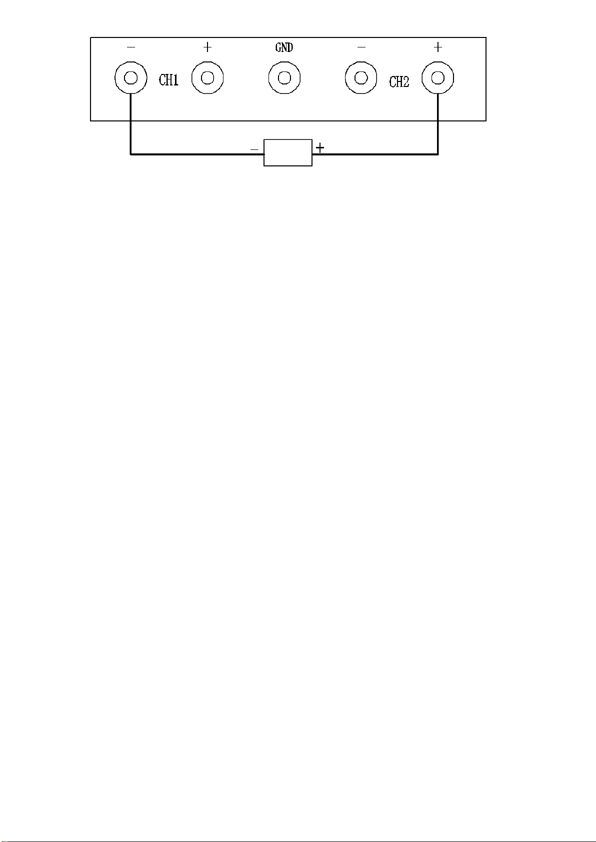
(2)Outputs are connected in series or parallel
1) Connect the input power cord and turn on the power switch (5). At this time, the
indicator lights up and the LED has a display. Note: The positive and negative outputs
when connected in series or parallel are positive to the positive pole of the second
channel (CH2); Take the negative pole of the first path (CH1) as the negative pole.
As shown in the figure below: (When selecting the in-line mode, it is forbidden to
connect the intermediate GND terminal posts).

2) Mode setting: according to the work needs, choose series mode or parallel mode. If
series connection is required, press the button (13), and the button will illuminate; If
parallel connection is required, press the button (14) and the button will illuminate.
After entering series or parallel mode: the output voltage, current and power are
displayed in the window of the first channel, and the display window of the second
channel is extinguished; Use the voltage knob (18) and current knob (19) of the first
way as the voltage and current adjustment knob. Use the C.C indicator (3) and C.V
indicator (4) of the first channel as constant current and constant voltage indicators.
3) Voltage stabilization setting: adjust the current knob (19) clockwise to the
maximum, and then adjust the voltage knob (18) to the required voltage value,
according to the positive and negative poles shown in the above figure, connect the
load and use normally. At this time, the power supply works in the regulated state,
and the voltage regulation indicator C.V(4) lights up, that is, the voltage is constant,
and the current changes with the change of load.
4) Current stabilization setting: adjust the voltage knob (18) to make the voltage
output 3-5V any value, and then adjust the current knob (19) counterclockwise.
According to the positive and negative poles shown in the figure above, short-circuit
the positive and negative poles with the wire, and adjust the current knob (19) to the
desired current value. Remove the short-circuit conductor, adjust the voltage value
required by the voltage knob (18), and connect the load. At this time, the power
supply should work in the steady current state, and the steady current indicator C.C
(3) is on, that is, the current is constant, and the output voltage changes with the
load. Note: If the steady current indicator C.C(3) is not lit and the C.V(4) light is on, it
means that the power supply is not working in the steady current state, and you
need to increase the knob (18) clockwise, increase the output voltage value, and the
output current will increase until the steady current indicator C.C (3) lights upAt this
point, the power supply enters a steady current state. The power supply outputs
positive and negative poles, and it is normal for there to be a slight abnormal sound
when there is a direct short circuit.
5. Precautions:
5.1. The wire diameter of the input and output should be large enough to avoid accidents
due to high current heating. Regularly check whether the terminal is screwed tightly
to avoid damage to the terminal due to loose terminal and large contact resistance.
5.2. This power supply adopts intelligent fan, when the temperature in the machine is
higher than 45 °C, the fan begins to rotate to dissipate heat. The air inlet and outlet
should leave more than 10cm heat dissipation space to avoid over-temperature
protection and affect normal use
5.3. The power supply shutdown has a buffer of 2-3 seconds, and the shutdown
has a delay of 1-2 seconds). Do not turn on and off the power frequently,
and the interval should be at least 10 seconds or more to avoid reducing the
service life of the power supply.

5.4. The protective grounding measures of the three-core power cord must be reliably grounded
to ensure safe use!
6. Maintenance
6.1. Substitution of fuse tube: If the fuse tube is blown out, the cause must be ascertained
before the same capacity fuse can be used. The fuse is in the lower part of the power
input port (2) on the rear panel and is pried out with a screwdriver for replacement.
6.2. Regularly dust the power supply, you can wipe the shell with a dry cloth, not with
organic solvents. The inside of the power supply is blown in from the ventilation hole
with high-pressure dry air to remove dust, and the shell cannot be disassembled and
cleaned to avoid accidents.
6.3. If the power supply is not used for a long time, the plug must be unplugged, the power
supply must be completely cut off, placed in a ventilated, dry and direct sunlight place,
and powered on for more than 30 minutes every six months, and the internal capacitor
of the power supply shall be empowered.
6.4. There are high-voltage lines in the machine, and non-professionals are strictly
forbidden to open the shell for maintenance to avoid accidents!
7. Common troubleshooting
phenomenon
Possible causes
Exclusion method
1. No electricity
1. The fuse is blown.
1. Press "6.1." Troubleshoot.
2. Enter the power cord open.
2. Check to fix the input line problem.
3. The plug is loose.
3. Plug in tightly.
2. No voltage output
IMG_256
1. Press "4.2.6." Relieve.
2. Constant current set to
minimum.
2. Adjust the knob (17 or 19) to the middle
position.
3. Over-temperature protection.
3. Turn off the power and wait for the power to
cool down before turning on.
3. The power supply
keeps restarting
1. Over-temperature protection.
1. Improve the working environment of the power
supply.
2. The fan does not spin.
2. The fan is stuck or damaged, resulting in poor
heat dissipation.
Note: If the above test still cannot be eliminated, please contact the dealer as soon as possible to get a
satisfactory answer.
8. Packing list
1 power supply and 1 book
1 qualified card , 1 power line.
For typographical errors and inconsistencies with the latest information in this manual, we
will promptly improve and compile them into the new version of the manual without
notice.
This manual suits for next models
4
Table of contents
Other Longwei Electric Power Supply manuals