Longwei Electric TPR-3002-2D User manual

1
In order to better use the power supply, please read the user
manual carefully before using and keeping it properly.
Warning: Do not connect any load to the power supply before it's turned on.
Likewise, make sure to disconnect the load before shutting down the power
supply. Damages to the power supply can happen if you do not follow this.
Such damages are not under warranty.
Warning: If you are running inductive load like magnetic coils, DC motors,
stepper motors, etc., make sure to change the voltage/current slowly, and
NEVER turn the power supply on or off with a inductive load connected!
1. Summary:
This serial multiplex output is high-precision power supply composed of
two way regulated output power supply and one-way fixed output power
supply. It uses four groups of three LED to display output voltage and current
values of the two way power supply respectively. In addition, two-way
regulated output power supply possesses automatic transfer function to
regulate voltage and current. And its circuit is composed of compensating pipe
power exhaustion steering circuit, operational amplifier and reference voltage
regulator with temperature compensation. Therefore, the circuit is stable and
reliable. The output power voltage of the power supply may randomly be
regulated from 0 to nominal voltage value. When it is in the state of current
regulation, the current regulation output current can continuously be regulated
from 0 to nominal current value. The two-way regulated power supply can be
randomly in series or in parallel in terms of the power supply. When it is in
series or in parallel, one circuit may track its voltage or current (in
parallel).The maximum output voltage can reach the total amount of the
two-way voltage rating when it is in series, while the maximum output current
can reach the total amount of the two-way current rating when it is in parallel.
The other regularly outputs 5V power supply, and the controlling part is
composed of single scale integrated regulator. The three groups of power

2
supply all have over-loading protection function, and over-loading or short
circuit in output will not damage power supply. This series of power supplies
are characterized by small volume, good performance and new style, and are
first choices for scientific and research institutions, colleges, factories and
electrical appliance maintenance units.
2. The specifications for parameters
2.1 Technical parameters
(1) Input voltage: 220V/110V±10% 50Hz/60Hz±2Hz (the output current is
less than 5A)
(2) Two-way regulated power supply:
Nominal output voltage: see table (can be regulated continuously)
Nominal output current: see table (can be regulated continuously)
Model voltage current Fixed output
TPR-3002-2D 2×0-30V 2×0-2A 5V/3A
TPR-3003-2D 2×0-30V 2×0-3A 5V/3A
TPR-3005-2D 2×0-30V 2×0-5A 5V/3A
TPR-6405-2D 2×0-64V 2×0-5A ——
(3) Current effect: CV≤ 1×10⁻⁴+ 0.5mV
CC≤ 2×10⁻³+ 6mA
(4) Load effect: CV≤ 1×10⁻⁴+ 2mV (output current≤3A)
≤ 1×10⁻⁴+ 5mV (output current>3A)
CC≤ 2×10⁻³+ 6mA
(5) Ripples and noises: CV≤0.5mVr.m.s. (Output current≤3A)
≤1.0mVr.m.s. (Output current>3A)0
CC≤3mAr.m.s.
(6) Protection: Protection of current limitation
(7) Instruction:

3
Digital voltmeter and ammeter, three LED digital displays.
Precision: voltmeter ±1%+2 figures Ammeter±2%+2 figures
(8) Other: two-way power supply can be in series and in parallel, one-way
main power supply may regulate output voltage when it is in series and in
parallel, at the moment the output voltage from the power supply strictly
tracks the output magnitude of voltage of the main power supply. When
regulating the parallel current ,the maim power supply may regulate current
regulation of the output current, at this moment the current output from power
supply strictly tracks the output current value from the main power supply.
(9) Regular output power supply
①Nominal output voltage: 5V±3%
②Nominal output current: 3A
③Current effect: ≤1×10⁻⁴+1mV
④Load effect: ≤1×10⁻³
⑤Ripples and noises: ≤ 0.5mVr.m.s
⑥Protection: Current limitation and protection for short circuit
(10) Environmental conditions: 0-400C relative humidity<90%
(11) Overall dimensions: 360mm×265mm×165 mm(Output current≤10A)
(The length is different in accordance with model)
(12) Working hours: constantly working more than 8 hours
2.2 Working principles
The regulated power supply is composed of rectifier filter circuit; auxiliary
power supply circuit; reference voltage circuit and voltage and current
regulation amplified circuit; regulated circuit and voltage and current
regulation sampling circuit etc.
The pane drawings are shown as Figure1.

4
Figure 1
When the output voltage is changed due to the change of power supply
voltage or load current, then the changed signals were compared by voltage
regulation sampling circuit and reference voltage, and the error signals were
amplified by comparison amplifier and the output voltage was regulated as
the set value by amplifying circuit controlling and regulating tube. Since the
comparison amplifier is composed of integrated operational amplifier,
therefore the power gain is very high, and the output terminal has minor
variation in voltage, which can also be regulated so as to achieve the goal of
highly stable output.
Current regulation is basically the same with voltage regulation, therefore
both are highly stable.
The function of every element in circuit is as the following:
After the voltage being reduced, the input 220V 50Hz or 110V 60Hz
alternating currents supply the main circuit rectifier and the auxiliary power
supply rectifier respectively. The main circuit rectifier selects circuit through
transformer winding (i.e. regulation tube power loss controlling circuit) and
connects to the transformer winding corresponding with output voltage. The
rectified filter circuit is composed of V7~V10, C6, and adopts bridge

5
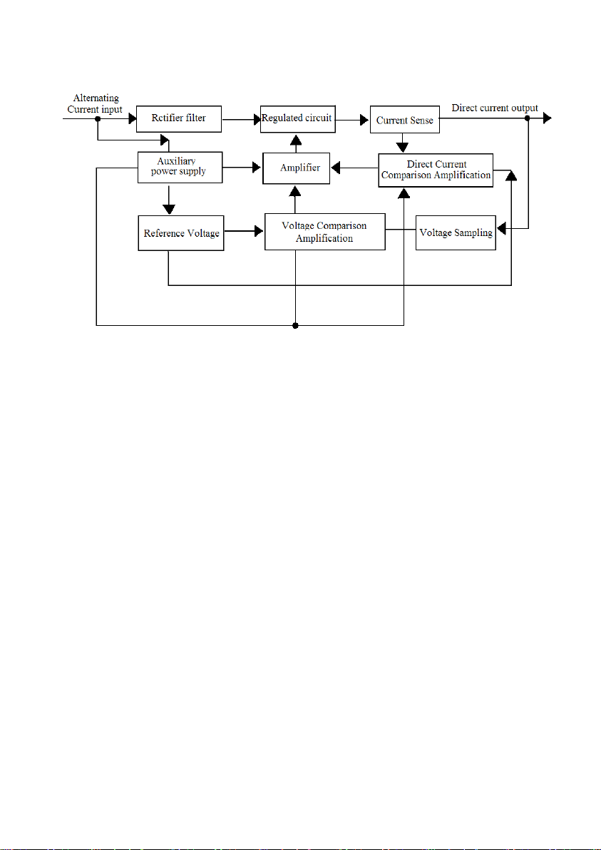
rectification and high volume capacitor filter, so the alternating component of
the output direct voltage is very small in quantity.
The auxiliary power supply composes auxiliary power circuit with N3,
V1~V4, V6, C1 ~C3 and relevant resistance. It is mainly used as the positive
and negative of the integrated operational amplifier and V5 integrated
reference voltage of regulator.
The selective circuit of transformer winding is composed of N4 (LM324
four operational amplifiers), V23~V28 and R20~R34,K1~K2.After the voltage
being parted by resistance, the input voltage of the regulation power supply is
added to the same reversal phase end of the two operational amplifiers, the
opposite reversal phase ends of the two operational amplifiers connect to two
voltages respectively. When the output voltage changes among 0~7.5V,
7.5V~ 15V, 15V ~22.5V, 22.5V ~30V, the output of the two operational
amplifiers have four combinations, namely, K1,K2,relays have four different
make-and-break combinations, that is, the alternative voltage attached to
circuit of the main rectifier filter has four different values, and they
correspond with the output voltage of the regulated power supply. When the
output voltage is high, the alternative voltage is also high, and when the
output voltage is low, consequently, the alternative voltage is low, thus
ensures the power consumption of high-power regulation tube not too high.
Reference voltage circuit is composed of V5 and R1, C4, and is produced
on the integrated regulator which passed through current-limiting resistance
R1, with temperature compensation by +12V of the auxiliary power supply,
therefore the reference voltage is very stable.
The output voltage sampling and voltage comparison amplified circuit are
composed of N1voltage comparator and relevant resistance capacitance. The
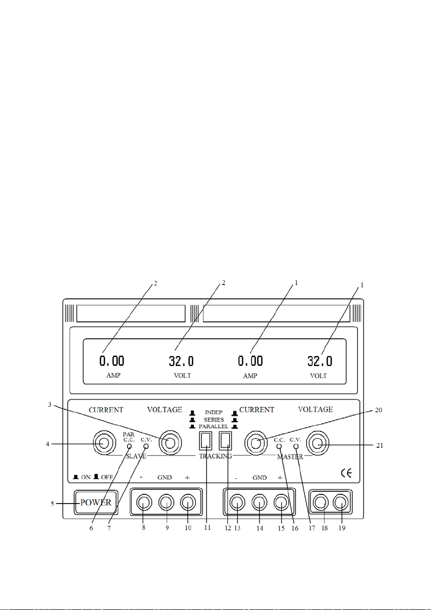
sampling voltage is directly taken from output wire connecting terminal X2,
and connects to the reversal phase of N1voltage comparator amplifier.
Reference voltage connects to the same phase of N1voltage comparator after
the voltage of the resistance R16, regulation resistance RP2, RP5being parted.
Because of the secondary voltage regulation with temperature compensation,

6
the reference voltage has good stability. RP6regulation resistance is placed
on the panel; the reference value of the same phase input terminal of the
comparison amplifier can only be changed by regulating the resistance
values of regulation resistance RP6so as to regulate the output magnitude of
voltage.
Current regulation sampling and comparison amplifying circuit are
composed of N2 and resistance R9~ R12 and regulation resistance RP1,RP4ect.
The voltage on the reversal terminal of the input operational amplifier N2is
reduced by the electricity produced by the circuit transmitting R10, R12, so the
voltage on the reversal terminal of the N2 operational amplifier reflects the
amount of output current. The input voltage of the same terminal is produced
by the reduced voltage reference. When the voltage on the same terminal is
higher than that on the reversal, the operational amplifier inputs higher level,
and the current regulation circuit doesn’t work and the power supply is in a
stable voltage position. When the voltage on the same terminal is lower than
that on the reversal, the operational amplifier is lower than level and the
current regulation circuit work and the circuit is in a current stable position.
For example: when the load resistance becomes smaller, and the output
current is going to increase and the voltage drop on the both terminals of R10,
R12 resistance will be increased, that is when the input voltage on the reversal
terminal of the operational amplifier N2 is increasing, for the reference
voltage on the same terminal remains unchanged, therefore the output
voltage of the operational amplifier will be dropped, which makes the output
voltage decrease, thus ensures the invariableness of the output current. For
this reason, changing the resistance value of RP4and RP5changes the
reference voltage, and the constant output current value is also changed.
V17 and V18 are two regulating tubes in parallel, which maintain certain
amount of output current and guarantee sufficient power, selected high-power
dynatron with the same parameters to be in parallel, and connected
equalizing resistance (R10, R12) in emitter to avoid damaging regulating tubes
because of uneven distribution of current.

7
This power supply uses two three binary voltmeters and ammeters to
display the output voltage and current at due time. Therefore, the output
voltage value and current value of every loop can be surveyed in a timely
manner.
3. The control and instruction of the panel
3.1 The function of every element on the panel
(1) Numeration table: indicating the major output voltage value and current
value.
(2) Numeration table: indicating the subordinate output voltage value and
current value.
(3) The subordinate voltage regulation output voltage regulation knob:
regulating subordinate output voltage value.
The map for the panel:
Figure2

8
(4) The subordinate current regulation output current regulation knob:
regulating subordinate output current value. (i.e. current limitation
protection regulation)
(5) Power switch when the power switch is placed “ON” (that is when the
power switch is lowered down), the machine is “on”, at this moment the
voltage regulation indicator light is on or current regulation light is on.
Conversely, the machine is off (that is when the switch is up).
(6) The subordinate current regulation or the two-way power supply parallel
indicator light: when the subordinate power supply is under the condition of
current regulation or when the two-way power supply is in parallel, the
indicator light is on.
(7) The subordinate voltage regulation indicator light: when the subordinate
power supply is in the position of voltage regulation, the indicator light is on.
(8) The subordinate direct current output negative terminal: the negative
electrode of output voltage connects to the negative terminal of the load.
(9) Cabinet ground terminal: the cabinet connects to the ground.
(10) The subordinate direct current output positive terminal: the anode of the
output voltage connects to positive terminal of the load.
(11) The control switch of two-way power supply is in independence, series
and parallel.
(Which output voltage is more than 30V or current is higher
than 10A will has not series and parallel function)
(12) The control switch of two-way power supply is in independence, series
and parallel.
(Which output voltage is more than 30V or current is higher
than 10A will has not series and parallel function)
(13) Main direct current output negative terminal: the negative electrode of
output voltage connects to the negative terminal of the load.
(14) Cabinet ground terminal: the cabinet connects to the ground.
(15) Main direct current output positive terminal: the anode of the output
voltage connects to positive terminal of the load.
(16) Main current regulation indicator light: when the main power supply is
under the condition of current regulation, the indicator light is on.

9
(17) Main voltage regulation indicator light: when the main power supply is
under the condition of voltage regulation, the indicator light is on.
(18) Regulator 5V direct power supply output negative terminal: the negative
electrode of the output voltage connects to the negative terminal of the load.
(19) Regulator 5V direct power supply output positive terminal: the anode of
the output voltage connects to the positive terminal of the load.
(20) Main current regulation output current adjusting knob: regulate the main
output current value (that is the regulation of current limit protection)
(21) Main voltage regulation output voltage adjusting knob: regulate the
main output voltage value.
3.2 The method for use
(1) The independent use of two-way regulated power supply
①Put the switch of (11) and (12) on the rising position (that is )
②When the regulated power supply is used as the voltage regulated power
supply, fist of all, the current regulation knobs (4) and (20) should be
clockwise regulated to the maximum, then turn on the power supply switch (5),
and regulate voltage regulation knobs (3) and (21) to regulate voltages of the
main and subordinate output direct currents to the necessary voltage values, at
his moment the voltage regulation indicator lights (7) and (17) will shine.
③When the regulated power supply is used as the current regulated power
supply, and after turning on the power supply switch (5), first, the voltage
regulation knobs (3) and(21) should be clockwise regulated to the maximum,
at the same the current regulation indicators (4) and (20) should be
counterclockwise regulated to the minimum, then connect the necessary load,
and clockwise regulate current regulation knobs (4) and (20) to make the
output current to the necessary regulated current value. At the moment,
voltage regulation indicator lights (7) and (17) are off; the current regulation
indicator lights (6) and (16) will shine.
④When used as voltage regulation power supply, the current regulation
knobs (4) and (20) should be regulated to the maximum, however, the power

10
supply can randomly set current limitation protection. The method for the
setting: turn on the power supply, and counterclockwise regulate the current
regulation indicators (4) and (20) to the minimum, then short connect
regulation knobs (4) and (20) to make output current equal to the necessary
current value of the current limitation protection, at this moment the current
the current limitation protection is set.
(2) Two-way regulation power supply used in series
Figure3
①When the power supply is used in series, please connect the output terminal
as Figure3 shows. Depress switch (11) (i.e. position) switch (12)
ejects(i.e. position) at this moment regulate the voltage regulation
knob(21) of the main power supply, and the subordinate output voltage of
strictly track the main output voltage, thus make the output voltage reaches
the total amount of the rated values of the two way currents (i.e. voltages
between terminal (8) and terminal(15)).
②Check the main and subordinate before the two power supplies are in series
whether the negative terminal has end connector to connect ground terminal, if
it has, the end connector should be cut off, otherwise it would cause short
circuit of the power supply when the two power supplies are in series.
③When the two power supplies are in parallel, the two output voltage are
controlled by main power supply, but still the current regulation of the two
way are independent. Therefore, when the two ways are in series, attention
should be paid to the position of (4) current regulation knob. If knob (4) is at

11
the end of counterclockwise position or the subordinate output current
exceeds the current limitation protection, at this moment, the output voltage
of the subordinate will no longer track the main output voltage. So knob (4)
should be clockwise turn to the maximum when the two ways are in series.
④when the two ways are in series, and if there is power output, the
corresponding lead of the application power and output power will reliably
connects the negative terminal of the main way and positive terminal of the
subordinate way. Since the internal part of the machine is short connected
through a switch, and when there is power output, the short connected switch
will pass the output current. But for a long time, it will do nothing to improve
the reliability of the whole machine.
(3) The two ways of regulation power supply used in parallel
Figure4
①When the power supply is used in parallel, please connect the output
terminal as Figure4 shows. Depress switch (11) (i.e. position) switch (12)
also pressed(i.e. position) at this moment, the two ways of power supply
are in parallel, regulation the voltage regulation knob(21) of the main power
supply, then the two output voltages are the same. Concurrently, the
subordinate current regulation indicator light (6) is on.
②When the two ways of power supply are in parallel, the current regulation
knob (4) of the subordinate power supply will not work. When the power
supply is used as current regulation power supply, only the main current
regulation knob (20) needs to be regulated, at this moment, the output current

12
of the main and subordinate leads will be controlled and they are the same.
The maximum output current can reach the total amount of currents of the
two leads.
③When the two ways of power supply are in parallel, if there is power output,
the corresponding lead of the application power and output power will reliably
connects the positive terminals of the main and subordinate ways and the
negative terminals of the main and subordinate ways so as to make load
reliably connects the output terminals of the ways. Otherwise, if the load is
only connected to output terminal of one way power supply, it will probably
cause the imbalance of the output current in the two ways of power supply, at
the same time, and it may cause damage to the switches of series circuit and
parallel circuit.
The output indicator of this power supply is three binary, if more precise
values need to be obtained, more precise measuring instrument should be
used to adjust in the outer circuit.
4. Matter need attention
4.1 The power supply has prefect protective functions, and 5V power supply
has reliable current limitation and short circuit protective functions. The
two-way regulated power supply has current limitation protective function.
Since compensating tube power loss controlling circuit has been set in the
circuit, so when there are short circuits in output, the power loss of the
high-power compensating tube is not so high, it will not cause any damage to
the power supply. However, when there are short circuits, this power supply
still has power loss, and in order to reduce unnecessary wearing of the
machine and loss of energy, the power should be switched off and fault
should be eliminated.
4.2 After using, it should be placed in dry and ventilated area and be kept
clean, if it is not used for a long time, the plug should plugged off.
4.3 When maintaining the regular power supply, the input power supply
should be cut off.

13
4.4 Power failures may be caused by improperly using power supply or
environment abnormal as well as the ineffectiveness of electron component
inside the machine. When there are power failures, the output voltage may
exceed the maximum voltage of the rated power, please pay attention when
use! Beware of unnecessary load damage.
4.5 The protective ground terminal of the three-core power cord should be
reliably connected with the ground to ensure safety in use.
5. Attachment
User manual 1
Power cord 1
6. Operating procedure
6.1 Place the power switch in “OFF” position.
6.2 Determine the correct input voltage as there is an 220V/110V switch
selection in the back panel.
6.3 Plug in power
6.4 Place the power switch in “ON” position
6.5 Regulate “VOLTAGE” and “CURRENT” knobs to necessary out voltage
and current values.
6.6 Connect external loading to “+” “-“outlet terminal.
6.7 When used in places with high demand, the output post head“-”must
reliably connects with post head “GND” so as to reduce output ripple
voltage.
7. Maintenance
7.1 Replacement of protective tube
If the protective tube burned out, the power supply will stop working, the
crisper should not be opened unless something goes wrong.

14
7.2 Regulation
The power supply is precisely regulated before it goes out; if there are
errors in precision in repairing, please follow the following procedures to
reregulate.
(1) Voltage regulation
①on the output terminal of the power supply, a multimeter with the precision
of±0.1% will be connected to measure the direct voltage.
②coarsely and fine regulated the voltage to the minimum value
③Regulate “MINVOLTS” vernier regulation, the reading of multimeter is 0
④coarsely and fine regulate the voltage to the maximum value (clockwise)
⑤Fine regulate “MAXVOLTS” to make the reading on the multimeter voltage
rating×1.05
⑥coarsely regulate to make the reading of the multimeter to voltage rating.
⑦Regulate the regulation resistance of the voltage meter to make the reading
of the voltage rating.
(2) Current regulation
①Turn the current to the minimum (counterclockwise)
②Connect a multimeter to the output terminal of the power supply to measure
current.
③Regulate “CURRENT” knob to make the reading of multimeter 0A
④coarsely and finely regulate the voltage to make it in the middle.
⑤. Regulate the current knob to make the reading of the multimeter the
maximum rating current value.
⑥Regulate fine regulation on the front panel regulation resistance “PCB” to
make the indication on the ammeter correspond with that of the multimeter.
This manual suits for next models
3
Table of contents
Other Longwei Electric Power Supply manuals
Popular Power Supply manuals by other brands

OCZ
OCZ STEALTH X STREAM 400W manual

BURG-WACHTER
BURG-WACHTER SANTEC VCA-24V-8A16P Quick installation guide

DEFA
DEFA 1204R Flex Installation and user guide

WAGO
WAGO 2787-2344 0000-00 0 Series manual

ULTIMATRON FRANCE
ULTIMATRON FRANCE ULT-1500BXS manual

EA-ELEKTRO-AUTOMATIK
EA-ELEKTRO-AUTOMATIK EA-HV 9000 Series manual