Lonking CDM307 User manual

CDM307
CDM308 Operation Manual
CDM312


Dear user:
Thank you for selecting LONKING skid steer loader!
This Operation Manual briefly introduces the safety and maintenance regulations of CDM 08 ( include
CDM 07 and CDM 12 ) skid steer loader for the use and reference of machine operators, maintainers
and technical managers.
Operation Manual is a guide for proper use and maintenance of this machine, therefore please carefully
read this manual before operating this machine.
Many faults are caused as a result of operator’s lack of reading this manual carefully and other human
reasons; a high level of safety awareness and good maintenance of the machine makes a safe, efficient
operation, and thus brings you more benefits. Therefore, please read and understand safety instructions
and strictly follow the related instructions before operating this machine. Incorrect operation, lubrication,
maintenance and repair of the machine are dangerous and may cause accident of human casualties.
We will continue to strive to improve product synthesis performance by ameliorating product design to
make the machine work more efficiently. We reserve the right to make changes to machine parameters
and configurations, any changes of contents about this manual will not be precaution, and any technical
parameters involved in this manual will not be taken as a check or test basis.
In order to better service you and improve product and service quality, if you find any problem or have a
good solution for the problem during the use of this machine and Operation Manual , please correspond
with us timely.
This manual is the third version.
Best wishes for your business!
LONKING Holdings Limited
Apr, 201

PREFACE
PREFACE
Manual Information
Please keep the Manual book safely in the cab for consult momentarily. Read and understand the
content before use the machine.
It may not include the improve and update parts of the product.
Some structures or accessories in the photos or pictures of this manual may be different from your
machine.
If you have any questions about the book, please contact Lonking China agents for lately information.
Structure
The manual include six parts, preface, safety information, machine information, machine operation,
maintenance part, hoisting and transportation of skid steer loader, common faults and troubleshooting,
reference tables of density of common materials.
Safety Information
Basic safety precautions and warnings are listed in this part. It also provides the contents and locations
of various warning labels on the machine.
Pro uct Information
Purposes, performance and specifications of the product are provided in this part.
Machine Operation
Instruments, switches and machine operation. Start-up and shut-down. Operation control.
Maintenance Section
The maintain periods of each part. Maintaintenance items should be maintained during the
maintaintenance period.
Hoisting an transporting securing instruction of ski steer loa er
Data for hoisting and transporting.
Common Faults an Troubleshooting
Common faults and troubleshooting are listed in this part.
Appen ix
Reference tables of density of common materials

CONTENT
1
CONTENT
DEAR USER............................................................................................................................................................. 1
PREFACE................................................................................................................................................................. 1
CHAPTER I SAFETY INFORMATION.............................................................................................................. 1
1.1 SAFETY PROMPT................................................................................................................................. 2
1.2 SAFETY LABEL..................................................................................................................................... 2
1. UNDERSTAND THE MEANING OF THE SAFETY SYMBOL.........................................................
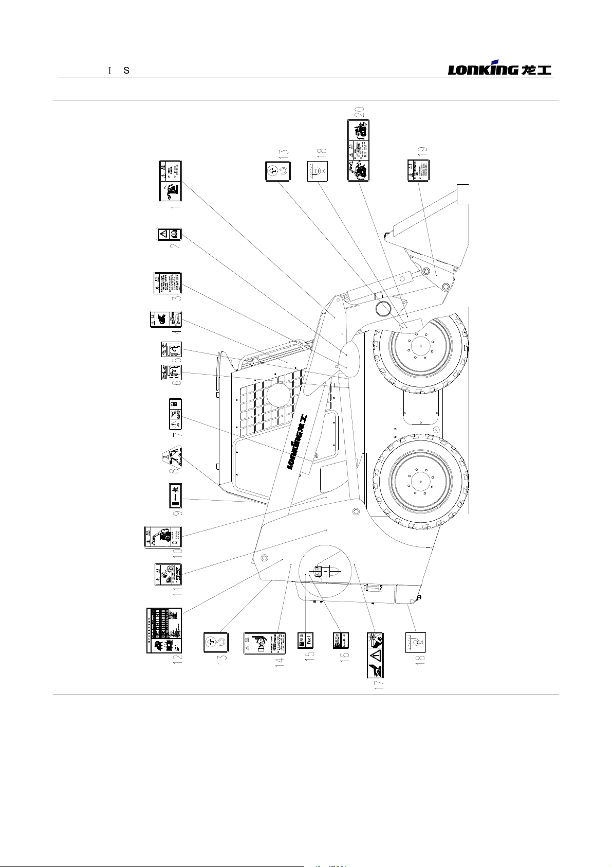
1.4 DISTRIBUTING SCHEMATIC OF SAFETY AND ADDITIVE LABELS.......................................... 4
1.5 OTHER SAFETY INFORMATION..................................................................................................... 14
CHAPTER II PRODUCT INFORMATION....................................................................................................... 22
2.1 MACHINE QUALIFICATION............................................................................................................... 2
2.2 MACHINE CONGIGURATION........................................................................................................... 2
2. PURPOSE............................................................................................................................................. 25
2.4 MACHINE SPECIFICATION............................................................................................................... 26
2.5 HYDRAULIC SYSTEM........................................................................................................................ 28
2.6 ELECTRICAL SYSTEM...................................................................................................................... 1
CHAPTER III MACHINE OPERATION........................................................................................................... 34
.1 CONTROL MACHENISM AND INSTRUMENT............................................................................... 5
.2 OPERATION OF SKID STEER LOADER........................................................................................ 6
. THE MAIN TECHNIC DATA OF COMMON USE............................................................................ 45
.4 FUEL,LUBRICANTS,GREASE AND THE COOLING WATER..................................................... 45
.5 INSECTION BEFORE OPERATION................................................................................................. 46
.6 STARTING AND PARKING................................................................................................................ 48
.7 OPERATION CONTROL.................................................................................................................... 49
CHAPTER IV MAINTENANCE SECTION...................................................................................................... 54
4.1 MAINTENANCE AND PRECAUTIONS OF SKID LOADER.......................................................... 55
4.2 MAINTENANCE OF MAIN COMPONENTS.................................................................................... 57
4.
MAINTENANCE AND PRECAUTION OF EQUIPPED ACCUMULATOR SKID STEER
LOADER
........................................................................................................................................................ 57

CONTENT
2
4.4 LUBRICATION...................................................................................................................................... 59
CHAPTER V HOISTING AND TRANSPORTATION SECURING OF SKID STEER LOADER............. 63
5.1 HOISTING AND TRANSPORTATION OF SKID LOADER............................................................ 64
CHAPTER VI COMMON FAULTS AND TROUBLE-SHOOTING............................................................... 67
6.1 COMMON TROUBLE-SHOOTING................................................................................................... 68
6.2 REASONS FOR ACCUMULATOR LOSING POWER .................................................................. 71
6. PRECATIONS BEFORE CHARGING THE ACCUMULATOR...................................................... 71
6.4 BATTERY CHARGING........................................................................................................................ 72
APPENDIX: REFERENCE TABLE OF DENSITY OF COMMON MATERIALS...................................... 73

CHAPTER
Ⅰ
SAFETY INFORMATION
1
CHAPTER I SAFETY INFORMATION
Please read and understand all the precautions of above Safety mask in the
manual or on the machine, and strictly observe these safety precautions during
operation or repair.

CHAPTER
Ⅰ
SAFETY INFORMATION
2
1.1 SAFETY PROMPT
1.1.1 Only those who experienced special training or got equivalent qualification can operate or
maintain this loader.
1.1.2 Most accidents that involve product operation, maintenance and repair are caused by failure
to observe basic safety rules or precautions.An accident can often be avoided by recognizing potentially
hazardous situations before an accident occurs. A person must be alert to potential hazards. This person
should also have the necessary training, skills and tools to perform these functions properly.
1.1. Improper operation, maintenance or repair on this product can be dangerous and could
result in injury or death.
1.1.4 Any modification
(
reconfigure
)
of this machine without getting the permission of Lonking
may disable the function or effect the safety, and shorten the service life of the machine.
1.1.5 Safety precautions and warnings are provided in this manual and on the machine. If these
hazard warnings are not heeded, bodily injury or death could occur to you or other persons, and cause
economic loss.
1.1.6 The hazards are identified by the "safety Warning Symbol " and followed by a " Warning
Label Word" such as "DANGEROUS","WARNING" or "CAUTION".
1.2 SAFETY LABEL
1.2.1 There are safety labels sticking to machine. This section will give a detailed description for
sticking location and the hazards . Please read and understand those safety labels before operation.
1.2.2 Make sure all the safety labels always are legible and in good conditions; .
1.2. Clean or replace the unclear labels.
1.2.4 If the picture on the label is not identified, please replace it.
1.2.5 Clean the labels with soft cloth, water and suds. Do not use solvents, gasoline or other
irritant chemical agents. These cleansers may disable the stickiness of the labels and make the labels
fall off the machine.
1.2.6 Replace any damaged and lost safety labels.
1.2.7 If any part sticking safety label is need of replacement, new safety label need to stick in the
changed part.
1.2.8 Various new safety labels are provided in any Lonking after-service institution.

CHAPTER
Ⅰ
SAFETY INFORMATION
1.3 UNDERSTAND THE MEANING OF THE SAFETY SYMBOL
1. .1 In the safety labels on the machine, words indicating degree or level of hazards -
DANGER (
危险
), WARNING (
警告
) or CAUTION (
注意
) - and use with the label of being careful. The
word "Danger" refers to a direct danger. If not avoid, it will result in personnel death or serious body
injuries.
1. .2 "DANGER" means that hazards are
existent. If not avoid, it will cause death or body
injuries.
Figure 1
1. . "WARNING" means that potential
hazards are existent. If not avoid, it will cause
casualties.
Figure 2
1. .4 "CAUTION" means that potential
hazards are existent. If not avoid, it will cause
minor injuries.
Figure 3
1. .5 "DANGER" or "WARNING" safety labels are setted near hazardous place. For common
safety protection, see "Caution" safety label.
1. .6 Safety signal words listed above may not appear in some warning labels of the machine.

CHAPTER
Ⅰ
SAFETY INFORMATION
4
1.4 DISTRIBUTING SCHEMATIC OF SAFETY AND ADDITIVE LABELS
FIGURE 4 DISTRIBUTING SCHEMATIC DIAGRAM OF SAFETY LABELS AND ADDITIVE LABELS

CHAPTER
Ⅰ
SAFETY INFORMATION
5
WARNING LABEL OF TIPPING HAZARD (1)
Label location: right inside the lift arm
The loading weight must be within the
range of rated load, not out of the range,
otherwise the machine may overturn. It may
damage the machine and cause serious
casualties.
Figure 4
-
--
-
1
WARNING USERS LABEL (2)
Label location: inside the cab
Do not operate the loader or work on the
machine before you have read and understand
the instruction and warnings in the Operation
and Maintenance Manuals. Failure to follow with
the instructions and warnings could result in
serious casualties. It is drivers' duty to comply
with operating regulations strictly.
Figure 4
-
--
-
2

CHAPTER
Ⅰ
SAFETY INFORMATION
6
WARNING LABEL FOR OPENING LOCKED PIN (3)
Label location: inside the cab
Make sure operate the machine strictly
according to the warning label, or damages of
machine may occur.
Figure 4
-
--
-
3
CRUSHING DANGER LABEL (4)
Label location: inside the cab
Make sure to operate the machine strictly
according to the warning label, or it may cause
machine damage or serious personal casualties.
Figure 4-4

CHAPTER
Ⅰ
SAFETY INFORMATION
7
RIGHT CONTROL HANDLE FUNCTION LABEL (5)
Label location: inside the right control handle hood
Inform the user that the right control handle
controls the right travel of the machine, tilting
back and dumping of the bucket.
Figure 4
-
--
-
5
LEFT CONTROL HANDLE FUNCTION LABEL (6)
Label location: inside the right control handle hood
Inform the user that the left control handle
controls left travel of the machine, lifting, droping
and floating of the lift arm.
Figure 4
-
--
-
6

CHAPTER
Ⅰ
SAFETY INFORMATION
8
SAFETY BRACING WARNING LABEL (7)
Label location: outside of the safety bar, on the right of the lift arm
When the lift arm is lifting for checking, put
down the securing bar. Otherwise, personnel
casualties may happen..
图
图图
图
4
-
--
-
7
EMERGENCY EXIT WARNING LABEL (8)
Label location: inside the cab, in the left back of the cab.
SAFETY EXIT WARNING LABEL (9)
Label location: inside the cab, on the rear glass.
Inform the user where emergency exit is.
Figure 4
-
--
-
9
Inform the user where emergency exit is.
Figure 4
-
--
-
8

CHAPTER
Ⅰ
SAFETY INFORMATION
9
PINCHING
HANDS
WARNING
LABEL
(10)
Label location: on the right rear side of the frame when the lift arm is down.
Never put your body here to avoid crushing
injuries or casualties.
Figure 4
-
--
-
10
START-UP HAZARDS LABEL OF THE ENGINE (11)
Label location: where the engine starts
Make sure operate the machine strictly
according to the warning label, or it may cause
machine damage or serious personal casualties.
Figure 4
-
--
-
11

CHAPTER
Ⅰ
SAFETY INFORMATION
10
MAINTENANCE AND LUBRICATION LABEL (12)
Label location: on the left rear side of the frame
Make sure to maintain and
lubricate the machine according to the
label. Otherwise, the machine damage
may be caused.
Figure 4
-
--
-
12
HOIST LABEL (13)
Label location: at both rear-upper sides of the frame , and both front sides of the frame.
When hitching the machine with the shackle
on the carriage. Before lifting, should adjust the
length of each lifting sling in order to keep the
balance of the machine. Pay attention to fasten
the hook. Make sure to operate with the special
hoisting tools only to avoid damages of the
engine hood,cab etc.
Figure 4
-
--
-
13

CHAPTER
Ⅰ
SAFETY INFORMATION
11
NO USE OF AETHER HAZARD (14)
Label location: at both rear-upper sides of the frame , both front sides of the frame.
Make sure to operate the machine strictly
according to the warning label, or it may cause
machine damage or serious personnal casualties.
Figure 4
-
--
-
14
FUEL LABEL (15)
Label location: inside the fuel oil tank on the frame
Fill the tank with clean fuel in time to avoid
engine stopping working. Filling wrong oil can
make the machine disable and damage the
machine.
Figure 4
-
--
-
15

CHAPTER
Ⅰ
SAFETY INFORMATION
12
LABEL OF HYDRAULIC OIL (16)
Label location: inside the hydraulic oil tank on the frame
Fill the tank with clean hydraulic oil in time to
avoid engine stopping working. Filling wrong oil
may make the machine disable and damage the
machine.
Figure 4
-
--
-
16
WARNING LABEL FOR THE RADIATOR AND THE FAN (17)
Label location: it is on the radiator.
In order to avoid body injuries, do not touch
the radiator when the machine is warming up. Do
not keep close to the fan when the fan is running.
Otherwise, serious injuries or death may happen.
Figure 4
-
--
-
17

CHAPTER
Ⅰ
SAFETY INFORMATION
1
WARNING LABEL FOR BINDING POSITION
(18)
Label location: it is in front of the frame, rear side of the balancing weight.
Inform users that where the binding position
is in the transportation, to bind this hook in order
to secure the machine in the transporting vehicle.
Figure 4
-
--
-
18
CHECKING QUICK DIS-CONNECT CONNETING LABEL (19)
Label location: it is on the beam of the bucket base.
Make sure to operate the machine strictly
according to the warning label, or it may cause
machine damage or serious personal casualties.
Figure 4
-
--
-
19
CRUSH HAZARD WARNING LABEL (20)
Label location: it is in the front of the frame.
Be not under the lift arm when it is raised,
unless it is supported.
Figure 4
-
--
-
20

CHAPTER
Ⅰ
SAFETY INFORMATION
14
1.5 OTHER SAFETY INFORMATION
1.5.1 OBSERVE SAFETY INDICATION
1.5.1.1 Before the maintenance and repair , hanging a warning signs on the start switch or control
handle, such as "No action"or other similar warning signs.
1.5.1.2 Know the working width of the machine. When the machine works in the neighbourhood of
the fence or the border barriers, personnels can keep distance of the machine.
1.5.1. Take care of high-tension wire and cable buried underground. If the Machine touches
these hazards, personal death or injuries may caused by electric shock .
1.5.2 SAFETY
1.5.2.1 When you operating the machine, do not wear loose clothing or jewelry tthat can snag on
controls or on other parts of the equipment.
1.5.2.2 Make sure that all protective guards and all covers are secured in place on the equipment.
1.5.2. Keep the machine free from foreign material. Remove debris, oil tools and other items from
the deck ,from walways, and from steps.
1.5.2.4 Keep the scattered items such as lunch boxes, tools and other items are not machine
parts.
1.5.2.5 Be familiar with special hand signals on the site, only one person should send the hand
signals.
1.5.2.6 Do not smoke when you repair the air conditioning,. Also, do not smoke if refrigerant gas
may be present. Inhaling the fumes that are released from a frame that contacts air conditioning
refrigerant can cause bodily harm or death. Inhaling gas air conditioning refrigerant through alighted
cigarette can cause bodily harm and death.
1.5.2.7 Do not put maintenance oil fluids into glass containers. Discharge all liquids into the
suitable container.
1.5.2.8 Do not operate the machine in the contaminative area. If not, and potential hazards may
exist, should take special action to protect the operator from the danger.
1.5.2.9 If hazards exist, e.g. fragments splashes caused by operating hydraulic hammer, it is
better to assemble the guards or guards that have equal protection effect such as anti-impact materials,
expanded protection and so on.
1.5.2.10 The cab is an important structure to protect the operator. The operator should replace the
cab if plastic deformations or cracking effects take place on the any part of the cab.
1.5.2.11 The use of cleanser should follow the requirements of manufacture. Reporting all the
items need to inspect and repair.
1.5.3 CHECK THE MACHINE
1.5. .1 Walk around the machine before starting the machine every time. Inspect the machine to
This manual suits for next models
2
Table of contents