Komatsu Utility SK815-5 turbo Install guide

WEBM005500


SK714-5 SK815-5 SK815-5 turbo
WEBM005500
00-1

SK714-5 SK815-5 SK815-5 turbo
CONTENTS
Page
10 STRUCTURE AND FUNCTION........................................................................................10-1
20 TESTING AND ADJUSTING.............................................................................................20-1
30 DISASSEMBLY AND ASSEMBLY..................................................................................30-1
40 MAINTENANCE STANDARD...........................................................................................40-1
CONTENTS
00-2

SK714-5 SK815-5 SK815-5 turbo
REVISED PAGES
00-2-1
The affected pages are indicated by the use of the
following marks. It is requested that necessary ac-
tions be taken to these pages according to table be-
low.
Pages having no marks are those previously revised or
made additions.
Mark Indication Action required
❍Page to be newly Add
●Page to be replaced Replace
( ) Page to be delete Discard
LIST OF REVISED PAGES
Mark Page Time of
revision Mark Page Time of
revision
00-1
00-2
00-2-1
00-2-2
00-3
00-4
00-5
00-6
00-7
00-8
00-9
00-10
00-11
00-12
00-13
00-14
00-15
00-16
00-17
00-18
00-19
00-20
00-21
00-22
10-1
10-2
10-3
10-4
10-5
10-6
10-7
10-8
10-9
10-10
10-11
10-12
10-13
10-14
10-15
10-16
10-17
10-18
10-19
10-20
10-21
10-22
10-23
10-24
10-25
10-26
10-27
10-28
10-29
10-30
10-31
10-32
10-33
10-34
10-35
10-36
10-37
10-38
10-39
10-40
10-41
10-42
10-43
10-44
10-45
10-46
10-47
10-48
10-49
10-50
10-51
10-52
10-53
10-54
10-55
10-56
10-57
10-58
10-59
10-60
10-61
10-62
10-63
10-64
10-65
10-66
10-67
10-68
10-69
10-70
10-71
10-72
10-73
10-74
10-75
10-76
10-77
10-78
10-79
10-80
10-81
10-82
10-83
10-84
10-85
10-86
10-87
10-88
10-89
10-90
10-91
10-92
10-93
10-94
10-95
10-96
10-97
10-98
10-99
10-100
10-101
10-102
10-103
10-104
10-105
10-106
20-1
20-2
20-3
20-4
20-5
20-6
20-7
20-8
20-9
20-10
20-11
20-12
20-13
20-14
20-15
20-16
20-17
20-18
20-19
20-20
20-21
20-22
20-23
20-24
20-25
20-26
20-27
20-28
20-29
20-30
20-31
20-32
20-32
20-34
20-35
20-36
20-37
20-38
20-39
30-1
30-2
30-3
30-4
30-5
30-6
30-7
30-8
30-9
30-10
30-11
30-12
30-13
30-14
30-15
30-16
30-17
30-18
30-19
30-20
30-21
30-22
30-23
30-24
30-25
30-26
30-27
30-28
30-29
30-30
30-31
30-32
30-33

SK714-5 SK815-5 SK815-5 turbo
Mark Page Time of
revision Mark Page Time of
revision
30-34
30-35
30-36
30-37
30-38
30-39
30-40
30-41
30-42
30-43
30-44
30-45
30-46
30-47
30-48
30-49
30-50
30-51
30-52
30-53
30-54
30-55
30-56
30-57
30-58
30-59
30-60
30-61
30-62
40-1
40-2
40-3
40-4
40-5
40-6
40-7
40-8
40-9
40-10
40-11
40-12
40-13
40-14
40-15
40-16
40-17
40-18
40-19
40-20
40-21
40-22
REVISED PAGES
00-2-2

SK714-5 SK815-5 SK815-5 turbo
SAFETY
00-3
IMPORTANT SAFETY NOTICE
Proper service and repair is extremely important for the safe operation of your machine.
TheserviceandrepairtechniquesrecommendedbyKomatsuUtilityanddescribeinthismanualarebothef-
fectiveandsafemethodsof operation.Some ofthese operationsrequire theuse oftoolsspecially designed
by Komatsu Utility for the purpose.
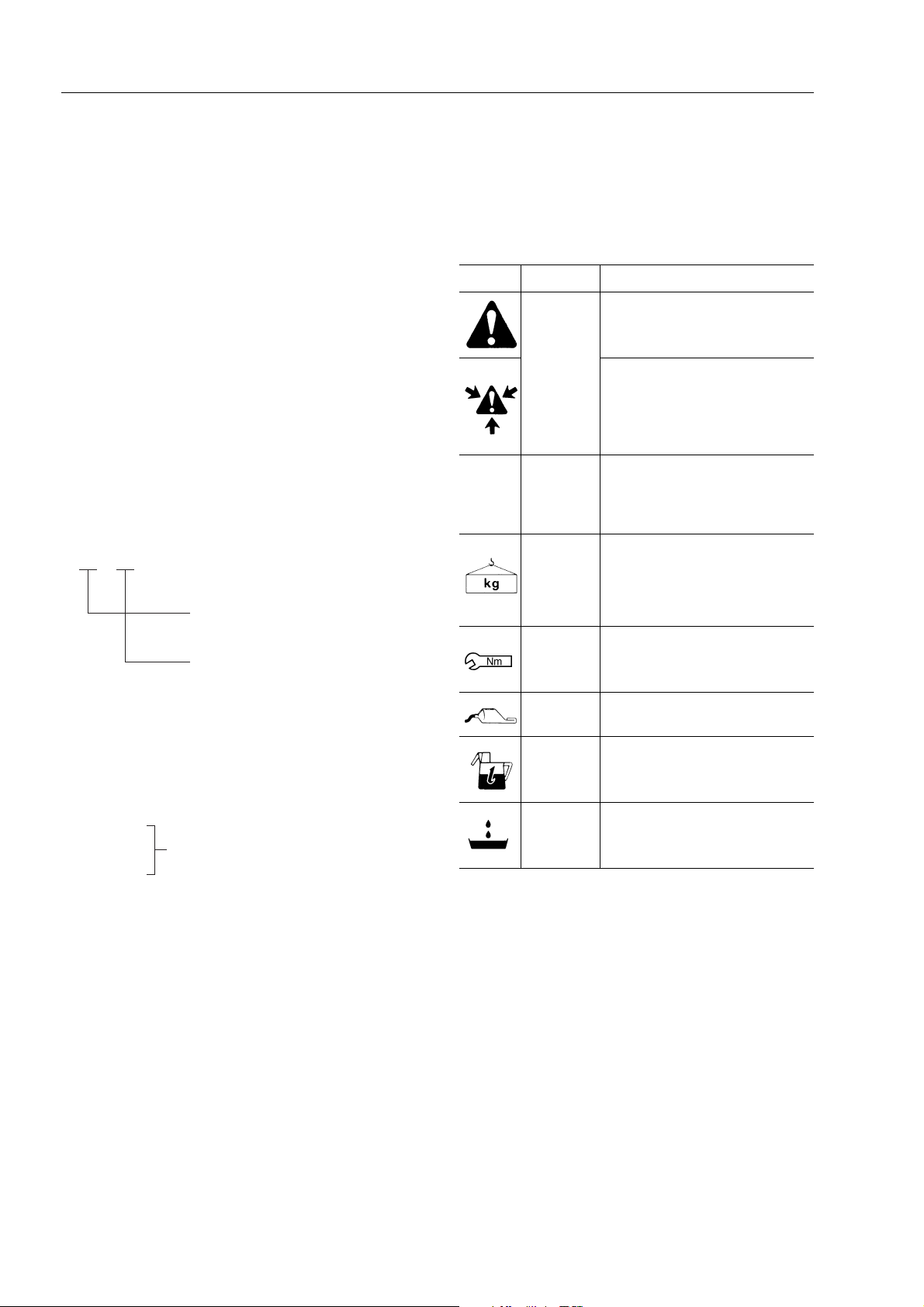
To prevent injury to workers, the symbols and are used to mark safety precautions in this manual.
Thecautionsaccompanyingthesesymbolsshouldalwaysbecarefullyfollowed.Ifanydangerarisesormay
possibly arise, first consider safety, and take necessary steps to face.
SAFETY
GENERAL PRECAUTIONS
Mistakes in operation extremely dangerous.
Read all the Operation and Maintenance Manual care-
fully BEFORE operating the machine.
1. Beforecarryingout anygreasingorrepairs,readall
theprecautionswrittenonthedecalswhicharesuck
on the machine.
2. Whencarryingoutanyoperation,alwayswearsafe-
ty shoes and helmet. Do not wear loose work
clothes, or clothes with buttons missing.
• Always wear safety glasses when hitting parts
with a hammer.
• Always wear safety glasses when grinding
parts with a grinder, etc.
3. If welding repairs are needed, always have a
trained, experienced welder carry out the work.
Whencarryingoutweldingwork,alwayswearweld-
ing gloves, apron,glasses, cap and other clothes
suited for welding work.
4. When carrying out any operation with two or more
workers, always agree on the operating procedure
before starting. Always inform your fellow workers
before starting any step of the operation. Before
starting work, hang UNDER REPAIR signs on the
controls in the operator’s compartment.
5. Keepalltoolsingoodconditionandlearnthecorrect
way to use them.
6. Decide a place in the repair workshop to keep tools
andremovedparts.Alwayskeepthetoolsandparts
in their correct places. Always keep the work area
cleanandmakesurethatthereisnodirtoroilonthe
floor.
Smokeonlyintheareasprovidedforsmoking.Nev-
er smoke while working.
PREPARATIONS FOR WORK
7. Before adding or making any repairs, park the ma-
chineonhard,levelground,andblockthewheelsto
prevent the machine from moving.
8. Beforestarting work,lower outrigger,bucket orany
other work equipment to the ground. If this is not
possible,useblocks to preventthework equipment
from falling down. In addition, be sure to lock all the
control levers and hang warning sign on them.
9. When disassembling or assembling, support the
machinewithblocks,jacksorstandsbeforestarting
work.
10. Removeallmudandoilfromthestepsorotherplac-
es used to get on and off the machine. Always use
thehandrails,laddersorstepswhengettingonoroff
the machine.
Never jump on or off the machine.
If it is impossible to use the handrails, ladders or
steps, use a stand to provide safe footing.
PRECAUTIONS DURING WORK
11. When removing the oil filler cap, drain plug or hy-
draulic pressure measuring plugs, loosen them
slowly to prevent the oil from spurting out.
Before disconnecting or removing components of
the hydraulic circuit and engine cooling circuit, first
remove the pressure completely from the circuit.
12. Thewaterandoilinthecircuitsarenothotwhenthe
engine in stopped, so be careful not to get burned.
Waitfor theoil waterto coolbeforecarrying outany
work on the cooling water circuits.
13. Beforestartingwork,removetheleadsfromthebat-
tery.Alwaysremove thelead fromthe negative(– )
terminal first.

SK714-5 SK815-5 SK815-5 turbo
SAFETY
00-4
14. When raising heavy components, use a hoist or
crane. Check that the wire rope, chains and hooks
are free from damage.
Always use lifting equipment whichhas ample ca-
pacity. Install the lifting equipment at the correct
places.
Use a hoist or crane and operate slowly to prevent
the component from hitting any other part.
Do not work with any part still raised by the hoist or
crane.
15. When removing covers which are under internal
pressure or under pressure from a spring, always
leavetwoboltsinpositiononoppositesides.Slowly
releasethepressure,thenslowlyloosentheboltsto
remove.
16. When removing components, be careful not to
break or damage the wiring.
Damage wiring may cause electrical fires.
17. Whenremovingpiping,stopthefueloroilfromspill-
ingout.Ifanyfueloroildripsontothefloor,wipeitup
immediately.
Fuel or oil on the floor can cause you to slip, or can
even start fires.
18. Asageneralrule,donotusegasolinetowashparts.
In particular, use only the minimum of gasoline
when washing electrical parts.
19. Be sure to assemble all parts again in their original
places. Replace any damage parts with new parts.
When installing hoses and wires, be sure that they
will not be damaged by contact with other parts
when the machine is being operated.
20. When installing high pressure hoses, make sure
that they are not twisted. Damaged tubes are dan-
gerous, so be extremely careful when installing
tubes for high pressure circuits. Also, check that
connecting parts are correctly tightened.
21. When assembling or installing parts, always use
specified tightening torques.
When installing the parts which vibrate violently or
rotateat highspeed, beparticularycareful tocheck
that they are correctly installed.
22. When aligning two holes, never insert your fingers
or hand.
23. Whenmeasuringhydraulicpressure,checkthatthe
measuringtooliscorrectlyassembledbeforetaking
any measurement.
24. Take sure when removing or installing wheels.

SK714-5 SK815-5 SK815-5 turbo
FOREWORD
Thisshop manualhas beenpreparedas anaid toimprovethe qualityof repairsby givingthe operatoranaccurate
understandingof theproduct andby showing himthecorrect wayto performrepairsand makejudgements. Makesure
you understand the contents of this manual and use it to full effect at every opportunity.
Thisshopmanual mainlycontainsthe necessarytechnical informationfor operations performedin aservicework-
shop.
Themanualis dividedintochaptersoneachmaingroupof components; thesechaptersarefurtherdividedintothe
following sections.
STRUCTURE AND FUNCTION
Thissectionexplainsthestructureandfunctionofeachcomponent.Itservesnotonlytogiveanunderstanding
of the structure, but also serves as reference material for troubleshooting.
TESTING AND ADJUSTING
This sections explains checks to be made before and after performing repairs, as well as adjustments to be
made at completion of the checks and repairs.
Troubleshooting charts correlating «Problems» to «Causes» are also included in this section.
DISASSEMBLY AND ASSEMBLY
This section explains the order to be followed when removing, installing, disassembling or assembling each
component, as well as precautions to be taken for these operations.
MAINTENANCE STANDARD
This section gives the judgement standards when inspecting disassembled parts.
FOREWORD
00-5
NOTE
The specifications contained in this shop manual are subject to change at anytime and without any no-
tice.
Contact your Komatsu Utility distributor for the latest information.

SK714-5 SK815-5 SK815-5 turbo
HOW TO READ THE SHOP MANUAL
VOLUMES
Shop manual are issued as a guide to carry out repairs.
These various volumes are designed to avoid duplicat-
ing the same information.
DISTRIBUTION AND UPDATING
Any additions, amendments or other changes will be
sent to Komatsu Utility distributors.
Getthemostup-to-dateinformationbeforeyoustartany
work.
FILING METHOD
1. See the page number on the bottom of the page.
File the pages in correct order.
2. Followingexamplesshowyouhowtoreadthepage
number.
Example:
3. Additionalpages:additional pagesare indicatedby
a hyphen (–) and number after the page number.
Fle as in the example.
Example:
REVISED EDITION MARK
(➀➁➂....)
When a manual is revised, an edition mark is recorded
on the bottom outside corner of the pages.
REVISIONS
Revised pages are shown on the LIST OF REVISED
PAGES between the title page and SAFETY page.
SYMBOLS
In order to make the shop manual greatly chelpful, im-
portant points about safety and quality are markedwith
the following symbols.
10 3
Item number (10. Structure and
Function)
Consecutive page number for each
item
-
10-4
10-4-1
10-4-2
10-5
Added pages
Symbol Item Remarks
Safety
Special safety precautions
are necessary when
performing the work.
Extra special safety precautions
are necessary when performing
the work because it is under in-
ternal pressure.
★Caution
Special technical precautions or
other precautions for preserving
standards are necessary when
performing the work.
Weight
Weight of parts or systems.
Caution necessary when select-
ing hoisting wire, or when work-
ing posture is important, etc.
Tightening
torque
Parts that require special atten-
tion for the tightening torque dur-
ing assembly.
Coat
Parts to be coated with adhe-
sives and lubricants etc.
Oil, water Places where oil, water or fuel
must be added, and their quan-
tity.
Drain Places where oil or water must
be drained, and quantity to be
drained.
HOW TO READ THE SHOP MANUAL
00-6

SK714-5 SK815-5 SK815-5 turbo
HOISTING INSTRUCTIONS
1. If a part cannot be smoothly removed from the ma-
chine by hoisting, the following checks should be
made:
• Check for removal of all bolts fastening the part
to the relative parts.
• Check for any part causing interference with
the part to be removed.
2. Wire ropes
1) Use adequate ropes depending on the weight of
parts to be hoisted, referring to the table below:
The allowable load value is estimated to be one-
sixth or one-seventh of the breaking strength of the
rope used.
2) Slingwireropesfromthemiddleportionofthehook.
Slinging near the edge of the hook may cause the
rope to slip off the hook during hoisting, and a se-
rious accident can result.
Hooks have maximum strength at the middle por-
tion.
3) Do not sling a heavy load with one rope alone, but
sling with two or more ropes symmetrically wound
on to the load.
Slingingwithoneropemaycauseturningoftheload
duringhoisting,untwistingoftherope, or slippingof
the rope from its original winding position on the
load, which can cause dangerous accidents.
4) Donot slinga heavyload withropesforming awide
hanging angle from the hook.
When hoisting a load with two or more ropes, the
force subjected to each rope will increase with the
hanging angles.
The table below shows the variation of allowable
load (kg) when hoisting is made with two ropes,
each of which is allowed to sling up to 1000 kg ver-
tically, at various handing angles.
Whentworopesslingaloadvertically,upto2000kg
of total weight can be suspended.
This weight becomes 1000 kg when two ropes
make a 120° hanging angle.
Ontheotherhand,tworopesaresubjectedtoanex-
cessiveforceaslargeas4000kgiftheyslinga2000
kg load at a lifting angle of 150°.
Heavy parts (25 kg or more) must be lifted
with a hoist etc. In the
Disassembly and Assem-
bly
section, every part weighing 25 kg or more is
clearly indicated with the symbol
WIRE ROPES
(Standard «S» or «Z» twist ropes
without galvanizing)
Rope diameter (mm) Allowable load (tons)
10.0
11.2
12.5
14.0
16.0
18.0
20.0
22.4
30.0
40.0
50.0
60.0
1.0
1.4
1.6
2.2
2.8
3.6
4.4
5.6
10.0
18.0
28.0
40.0
HOISTING INSTRUCTIONS
00-7

SK714-5 SK815-5 SK815-5 turbo
STANDARD TIGHTENING TORQUE
The following charts give the standard tightening torques of bolts and nuts.
Exceptions are given in section of «Disassembly and Assembly».
1. STANDARD TIGHTENING TORQUE OF BOLTS AND NUT
This torque table does not apply to bolts or nuts which have to fasten nylon or other parts non-ferrous metal washer.
★Nm (newton meter): 1 Nm = 0.102 kgm
Thread
diameterofbolts
(mm)
Pitch of
bolts
(mm)
Width across flat
(mm)
kgmNmkgmNm
6
8
10
12
14
1
1.25
1.5
1.75
2
10
13
17
19
22
8
6
8
10
12
0.96±0.1
2.3±0.2
4.6±0.5
7.8±0.8
12.5±1
9.5±1
23±2
45±4.9
77±8
122±13
1.3±0.15
3.2±0.3
6.5±0.6
11±1
17.5±2
13.5±1.5
32.2±3.5
63±6.5
108±11
172±18
16
18
20
22
24
2
2.5
2.5
2.5
3
24
27
30
32
36
14
14
17
17
19
19.5±2
27±3
38±4
52±6
66±7
191±21
262±28
372±40
511±57
644±70
27±3
37±4
53±6
73±8
92±10
268±29
366±36
524±57
719±80
905±98
27
30
33
36
39
3
3.5
3.5
4
4
41
46
50
55
60
19
22
24
27
----
96±10
131±14
177±20
230±25
295±33
945±100
1287±140
1740±200
2250±250
2900±330
135±15
184±20
250±27
320±35
410±45
1329±140
1810±190
2455±270
3150±350
4050±450
STANDARD TIGHTENING TORQUE
00-8

SK714-5 SK815-5 SK815-5 turbo
2. TIGHTENING TORQUE FOR NUTS OF FLARED
Use these torques for nut part of flared.
Thread diameter
of nut part
(mm)
Width across flats
of nut part
(mm)
TIGHTENING TORQUE
kgm Nm
1/2” - 20
9/16” - 18
3/4” - 16
7/8” - 14
1.1/16 - 12
1.5/16 - 12
1.5/8 - 12
22
33
17
17
22
27
32
38
50
27
41
2.6±0.5
4±0.5
6.7±2
8±2
9.7±3
17±3
20±5
8±2
20±5
25.5±4.9
39.2±4.9
65.7±19.6
78.5±19.6
95.15±29.4
166.7±29.4
196.2±49
78.5±19.6
196.2±49
Thread diameter
of nut part
(mm)
Width across flats
of nut part
(mm)
TIGHTENING TORQUE
kgm Nm
9/16” - 18
11/16” - 16
13/16” - 16
1” - 14
1.3/16 - 12
1.7/16 - 12
1.11/16 - 12
2” - 12
17
22
24
30
36
41
50
57
2.3–2.5
3.4–3.9
5.2–5.8
8.2–9.2
12.2–13.3
15.3–17.3
18.4–20.4
20.4–24.4
23–25
33–38
51–57
80–90
120–130
150–170
180–200
200–240
Sealing surface
STANDARD TIGHTENING TORQUE
00-9

SK714-5 SK815-5 SK815-5 turbo
COATING MATERIALS
The recommended coating materials prescribed in Komatsu Utility Shop Manuals are listed below:
Nomenclature Code Applications
Adhesives
Bostik 99 Used to apply rubber pads, rubber gaskets and cork plugs.
Loctite 406 Usedtoapplyresin,rubber,metallicandnon-metallicpartswhenafast,strong
seal is needed.
Loctite 222 Used for low resistance locking of screws, check nuts and adjustment nuts.
Loctite 242 Topreventthelooseningofbolts,nutsandplugsandtheleakageofoil.Usedfor
medium resistance locking of screws and nuts of every type, and for locking
keys and bearings.
Loctite 262 Usedforhighresistantofthreadedpartsthatcanberemovedwithnormaltools.
Loctite 270 Used for high resistant locking and for sealing threaded parts, bolts and stud
bolts.
Loctite 542 Used for sealing the union threads for hydraulic tubes.
Loctite 573 Usedforsealingratherexactplanesurfaceswhentheoptionofpossiblefuture
dismantling is required.
Loctite 601 Usedforhighresistantlockingofmechanicalcomponentsthatcanberemoved
only after heating
Loctite 675 Used to lock cylindrical couplings and for the permanent locking of threaded
parts, and also to lock shafts to bearings, gears, pulleys, pins, bushings, etc.
Gasket sealant
Loctite 542 Used by itself to seal grease fittings, tapered screw fittings and tapered screw
fittings in hydraulic circuits of less than 50 mm in diameter.
Loctite 510 Used by itself on mounting flat surface
(Clearance between surfaces within 0.2 mm)
Loctite 518 Used by itself on mounting flat surface
(Clearance between surfaces within 0.5 mm
Antifriction compound
(Lubricant including
Molybdenum disulfide) Litio EP MS2
NLGI 2 Applied to bearings and taper shaft to facilitate press-fitting and to prevent
sticking, burning or rusting.
Grease
(Lithium grease) Litio EP
NLGI 2 Applied to bearings, sliding parts and oil seals for lubrication, rust prevention
and facilitation of assembling work.
Vaseline
-----
Used for protecting battery electrode terminals from corrosion
COATING MATERIALS
00-10

SK714-5 SK815-5 SK815-5 turbo
ELECTRIC
In the wiring diagrams various colour and symbols are employed to indicate the thickness of wires.
This wire code table will help you understand WIRING DIAGRAMS.
Example: R–N 1.5 indicates a cable having a nominal number 1.5 and red coating with black stripe.
CLASSIFICATION BY THICKNESS
CLASSIFICATION BY COLOUR AND CODE
COMPOSITION OF THE COLOURS
The coloration of two-colour wires is indicated by the composition of the symbol listed.
Example: G–V = Yellow-Green with longitudinal colouring
G/V = Yellow-Green with transversal colouring
Nominal
number
Copper wire Cable O.D.
(mm) Current rating
(A)
Number
strands Ø of strands
(mm) Cross section
(mm)
0.5 16 0.20 0.35 1.55 3.5
1 14 0.30 0.99 2.80 11
1.5 21 0.30 1.48 3.35 14
2.5 35 0.30 2.47 3.80 20
4 56 0.30 3.95 4.60 28
6 84 0.30 5.93 5.20 37
Primary Auxiliary
Code A A–B A/B A–G – A–N A/N A–R A–V A/V
Colour Light Blue Light Blue – White Light Blue–Yellow Light Blue–Black Light Blue–Red Light Blue–Green
Code B B–G – B–N B/N B–R B/R – – – –
Colour White White–Yellow White–Black White–Red – –
Code C C–B C/B C–L – C–N C/N – – – –
Colour Orange Orange–White Orange–Blue Orange–Black – –
Code G G–N G/N – G/R – – – – – –
Colour Yellow Yellow–Black Yellow–Red – – –
Code H H–L – H–N – H–R H/R – – – –
Colour Grey Grey–Blue Grey–Black Grey–Red – –
Code L – L/B L–G L/G L–N L/N L–R L/R – –
Colour Blue Blue–White Blue–Yellow Blue–Black Blue–Red –
Code M M–B M/B M–N – M–V – – – – –
Colour Brown Brown–White Brown–Black Brown–Green – –
CodeN ––––––––––
ColourBlack–––––
Code R R–G – R–N R/N R–V – – – – –
Colour Red Red–Yellow Red–Black Red–Green – –
Code S S–G – S–N S/N – – – – – –
Colour Pink Pink–Yellow Pink–Black – – –
Code V V–B V/B V–N V/N – – – – – –
Colour Green Green–White Green–Black – – –
Code Z Z–B – Z–N Z/N – – – – – –
Colour Violet Violet–White Violet–Black – – –
ELECTRIC WIRE CODE
00-11

SK714-5 SK815-5 SK815-5 turbo
WEIGHT TABLE
This weight table is a guide for use when transporting or handling components. Unit: kg
Machine model SK714-5 SK815-5 SK815-5 turbo
Engine assembly - Muffler - Exhaust pipe 200 200 200
Radiator 22 22 22
Hydraulic oil tank (without oil) 21.5 21.5 21.5
Engine hood 14.5 14.5 14.5
Cabin (without seat) 215 215 215
Seat:
• standard
• witj suspension 10
16 10
16 10
16
Engine-pump group 278–285 283–290 283–290
Piston pump:
• standard
• High-Flow 78
84 82
88 82
88
Wheel, assy. (standard) 43 44 44
Control valve:
• 3-spool (standard)
• 4-spool (High-Flow) 19
21.5 19
21.5 19
21.5
Work equipment (without bucket)
• Arm
• Work equipment support
• Bucket (L=1460 mm)
• Tilt cylinder
• Dump cylinder
280
49
159
17,3
12
295
49
171,5
16,8
12
295
49
171,5
16,8
12
WEIGHT TABLE
00-12

SK714-5 SK815-5 SK815-5 turbo
TABLE OF OIL AND COOLANT QUANTITIES
✽ ASTM D975 N.
IMPORTANT:
(1) Whenthedieseloilsulphurcontentislessthen 0.5%,changetheengine oil accordingtothe periodicmaintenance
intervalsindicatedintheoperationandmaintenancemanual.Inthedieseloilsulphurcontentexceeds0.5%change
the engine oil according to the following table:
(2) Whenstartingtheengineattemperaturesbelow0°C,useengineoilSAE10W,20W-20and10W-30,evenifduring
the day the temperature increases by 10 °C.
(3) Useengine oilwith CDclassification;if oilwithCD classificationis used,reduce theengineoilchange intervalbya
half.
(4) Useoriginalproducts,whichhavecharacteristicsspecificallyformulatedandapprovedfortheengine,thehydraulic
circuit of equipment and for reductions.
First filling quantity:
total quantity of oil, including the oil for the components and pipes.
Oil change quantity:
quantity of oil necessary to fill the system or unit during the normal inspection and maintenance operations.
ASTM: American Society of Testing and Materials
SAE: Society of Automotive Engineers
API: American Petroleum Institute
RESERVOIR KIND OF
FLUID
AMBIENT TEMPERATURE CAPACITY (ᐉ)
--
30
--
20
--
10 0 10 20 30 40 50°C Specified Refill
Engine oil pan OIL
• API CD 88
Hydraulic system
and hydrostatic
trasmissione
OIL
• API CD 38 27
Hydraulic circuit
with biodegradable
oil 38 27
Final transmission
case (ea.) OIL
• API CD 15.5 15.5
Fuel tank DIESEL OIL
SK714-5
SK815-5:
38
SK815-5 turbo:
50
–
Engine cooling
system
WATER +
ANTIFREEZE
9–
PERMANENT
COOLANT
9–
Sulphur content Engine oil change interval
from 0.5 to 1.0% 1/2 of regular interval
over 1.0% 1/4 of regular interval
SAE 10W-30
SAE 10W
SAE 5W-30
SAE 30
SAE 40
SAE 10W
SAE 5W-30
SAE 10W-30
✽
ASTM D975 N.2
TABLE OF OIL AND COOLANT QUANTITIES
00-13

PAGE INTENTIONALLY
LEFT BLANK

SK714-5 SK815-5 SK815-5 turbo
CONVERSION TABLE
METHOD OF USING THE CONVERSION TABLE
The conversion table in this section is provided to enable simple conversion of figures.
For details of the method of using the conversion table, see the example given below.
EXAMPLE
• Method of using the conversion table to convert from millimeters to inches.
1. Convert 55 mm into inches.
1 - Locate the number 50in the vertical column at the left side, take this as , then drow a horizontal line from
.
2 - Locate the number 5 in the row across the top, take this as , then draw a perpendicular line down from .
3 - Take the point where the two lines cross as . This point gives the value when converting from mil-
limeters to inches. Therefore, 55 mm =2.165 in.
2. Convert 550 mm into inches
1 - The number 550 does not appear in the table, so divide by 10 (move the decimal point one place tothe left) to
convert it to 55 mm.
2 - Carry out the same procedure as above to convert 55 mm to 2.165 in.
3 - Theoriginalvalue(550mm)wasdividedby10,somultiply2.165in.by10(movethedecimalpointoneplaceto
the right) to return to the original value. This gives 550 mm = 21.65 in.
From millimeters to inches 1 mm = 0.03937 in.
0 1 2 3 4 5 6 7 8 9
0
10
20
30
40
50
60
70
80
90
0
0.394
0.787
1.181
1.575
1.969
2.362
2.756
3.150
3.543
0.039
0.433
0.827
1.220
1.614
2.008
2.402
2.795
3.189
3.583
0.079
0.472
0.866
1.260
1.654
2.047
2.441
2.835
3.228
3.622
0.118
0.512
0.906
1.299
1.693
2.087
2.480
2.874
3.268
3.661
0.157
0.551
0.945
1.339
1.732
2.126
2.520
2.913
3.307
3.701
0.197
0.591
0.984
1.378
1.772
2.165
2.559
2.953
3.346
3.740
0.236
0.630
1.024
1.417
1.811
2.205
2.598
2.992
3.386
3.780
0.276
0.669
1.063
1.457
1.850
2.244
2.638
3.032
3.425
3.819
0.315
0.709
1.102
1.496
1.890
2.283
2.677
3.071
3.465
3.858
0.354
0.748
1.142
1.536
1.929
2.323
2.717
3.110
3.504
3.898
A
A
B
C C
CONVERSION TABLE
00-15
A
B
C

SK714-5 SK815-5 SK815-5 turbo
From mm to in. 1 mm = 0.03937 in.
From kg to lb. 1 kg = 2.2046 lb.
0123456789
0
10
20
30
40
50
60
70
80
90
0
0.394
0.787
1.181
1.575
1.969
2.362
2.756
3.150
3.543
0.039
0.433
0.827
1.220
1.614
2.008
2.402
2.795
3.189
3.583
0.079
0.472
0.866
1.260
1.654
2.047
2.441
2.835
3.228
3.622
0.118
0.512
0.906
1.299
1.693
2.087
2.480
2.874
3.268
3.661
0.157
0.551
0.945
1.339
1.732
2.126
2.520
2.913
3.307
3.701
0.197
0.591
0.984
1.378
1.772
2.165
2.559
2.953
3.346
3.740
0.236
0.630
1.024
1.417
1.811
2.205
2.598
2.992
3.386
3.780
0.276
0.669
1.063
1.457
1.850
2.244
2.638
3.032
3.425
3.819
0.315
0.709
1.102
1.496
1.890
2.283
2.677
3.071
3.465
3.858
0.354
0.748
1.142
1.536
1.929
2.323
2.717
3.110
3.504
3.898
0123456789
0
10
20
30
40
50
60
70
80
90
0
22.05
44.09
66.14
88.18
110.23
132.28
154.32
176.37
198.42
2.20
24.25
46.30
68.34
90.39
112.44
134.48
156.53
178.57
200.62
4.41
26.46
48.50
70.55
92.59
114.64
136.69
158.73
180.78
202.83
6.61
28.66
50.71
72.75
94.80
116.85
138.89
160.94
182.98
205.03
8.82
30.86
51.91
74.96
97.00
119.05
141.10
163.14
185.19
207.24
11.02
33.07
55.12
77.16
99.21
121.24
143.30
165.35
187.39
209.44
13.23
35.27
57.32
79.37
101.41
123.46
145.51
167.55
189.60
211.64
15.43
37.48
59.53
81.57
103.62
125.66
147.71
169.76
191.80
213.85
17.64
39.68
61.73
83.78
105.82
127.87
149.91
171.96
194.01
216.05
19.84
41.89
63.93
85.98
108.03
130.07
152.12
174.17
196.21
218.26
CONVERSION TABLE
00-16
This manual suits for next models
1
Table of contents
Other Komatsu Utility Mini Skid Steer manuals