LORAL TERRACOM AN / PRC- 1 04(A) User manual

TM 11-5820-919-40-2
TECHNICAL MANUAL
GENERAL SUPPORT MAINTENANCE MANUAL
RADIO SET
AN / PRC- 1 04(A)
(NSN 5820-01-141-7953)
HEADQUARTERS, DEPARTMENT OF THE ARMY
15 JANUARY 1986

TM 11-5820-919-40-2
SAFETY STEPS TO FOLLOW IF SOMEONE IS THE VICTIM OF ELECTRICAL SHOCK
DO NOT TRY TO PULL OR GRAB THE INDIVIDUAL
IF POSSIBLE, TURN OFF THE ELECTRICAL POWER
IF YOU CANNOT TURN OFF THE ELECTRICAL POWER, PULL, PUSH, OR LIFT THE PERSON TO SAFETY USING A DRY WOODEN POLE OR A DRY ROPE OR SOME OTHER INSULATING MATERIAL
SEND FOR HELP AS SOON AS POSSIBLE
AFTER THE INJURED PERSON IS FREE OF CONTACT WITH THE SOURCE OF ELECTRICAL SHOCK, MOVE THE PERSON A SHORT DISTANCE AWAY AND IMMEDIATELY START ARTIFICIAL RESUSCITATION
5
1
2
3
4
5
A

TM 11-5820-919-40-2
HIGH VOLTAGE
is used in the operation of this equipment
DEATH ON CONTACT
may result if personnel fail to observe safety precautions
Never work on electronic equipment unless there is another person nearby who is
familiar with the operation and hazards of the equipment and who is competent in administering
first aid. When the technician is aided by operator’s, he must warn them about dangerous areas.
Whenever possible, the power supply to the equipment must be shut off before beginning
work on the equipment. Take particular care to ground every capacitor likely to hold a dangerous potential.
When working inside the equipment, after the power has been turned off, always ground every part before
touching it.
Be careful not to contact high-voltage connections or 115 volt ac input connections when installing or
operating this equipment.
Whenever the nature of the operation permits, keep one hand away from the equipment to reduce
the hazard of current flowing through the body.
Warning: Do not be misled by the term “low voltage.” Potentials as low as 50 volts may cause death under
adverse conditions.
For Artificial Respiration, refer to FM 21-11.
B

TM 11-5820-919-40-2
SAFETY SUMMARY
The following are general safety precautions that are not related to any specific procedures and therefore do not appear elsewhere in this publication. These are
recommended precautions that personnel must understand and apply during many phases of operation and maintenance.
KEEP AWAY FROM LIVE CIRCUITS
Operating personnel must at all times observe all safety regulations. Unless specifically directed in this manual, do not replace components or make adjustments
inside the equipment with any power supply turned on. Under certain conditions, dangerous potentials may exist in the power supplies when the power control is in
the off position. To avoid causalities, always remove power and discharge and ground a circuit before touching it.
DO NOT SERVICE OR ADJUST ALONE
Under no circumstances should any person reach into or enter the enclosure for the purpose of servicing or adjusting the equipment except in the presence of
someone who is capable of rendering aid.
RESUSCITATION
FIRST AID
Each person engaged in electrical operations will be trained in first aid, particularly in the technique of mouth to mouth resuscitation and closed chest heart massage
(FM 21-11).
The following warnings appear in this volume, and are repeated here for emphasis.
WARNING
A 3-wire (line, neutral, and safety ground) AC line power connections is required when operating the equipment. If a 3-wire safety grounded AC power receptacle is
not available, a separate ground wire must be installed from the chassis ground to an earth ground. Without an adequate ground, the equipment chassis and frame
will float to a dangerously high potential.
WARNING
Lethal voltage is used in the operational checkout of this unit. Death on contact may result if personnel fail to observe the following safety precautions. Remove
watches and rings and exercise extreme caution when working inside the equipment throughout the remainder of this procedure.
C

TM 11-5820-919-40-2
WARNING
Prior to performing the following functions all electrical power is to be removed from the system. External power
disconnected and a "MAINTENANCE IN PROGRESS" tag attached or power switches will be locked out to prevent
inadvertent energizing of the system.
WARNING
Lifting heavy equipment incorrectly can cause serious injury. Do not try to lift more than 35 pounds by yourself. Get a
helper. Bend legs while lifting. Don't support heavy weight with your back.
D

TM 11-5820-919-40-2
Technical Manual HEADQUARTERS
DEPARTMENT OF THE ARMY
No. 11-5820-919-40-2 Washington, DC, 15 January 1986
GENERAL SUPPORT MAINTENANCE MANUAL
RADIO SET
AN/PRC-104A
(NSN 5820-01-141-7953)
REPORTING OF ERRORS AND RECOMMENDING IMPROVEMENTS
You can help improve this manual. If you find any mistakes or if you know of a way to improve the procedures, please let us
know. Mail your letter, DA Form 2028 (Recommended Changes to Publications and Blank Forms), or DA Form 2028-2 located
in the back of this manual direct to: Commander, US Army Communications-Electronics Command and Fort Monmouth, ATTN:
AMSELME-MP, Fort Monmouth, NJ 07703-5007. A reply will be furnished to you.
TABLE OF CONTENTS
Section Page
WARNINGS ...................................................................................................................................................................A through D
O GENERAL...................................................................................................................................................................0-1
0-1 Scope.........................................................................................................................................................0-1
0-2 Consolidated Index of Army Publications and Blank Forms ........................................................................ 0-1
0-3 Maintenance Forms, Records and Reports ................................................................................................0-1
0-4 Reporting Equipment Improvement Recommendations .............................................................................0-1
0-5 Administrative Storage................................................................................................................................0-1
0-6 Destruction of Army Electronics Materiel ....................................................................................................0-1
i

TM 11-5820-919-40-2
TABLE OF CONTENTS
Paragraph Page
1. INTRODUCTION ....................................................................................1
APPENDIX A - REFERENCES ...............................................................1
NOTE
Maintenance Kit,OA-9169/GRC-213,ls
available for Army use In maintaining
this equipment. LIST OF ILLUSTRATIONS
Figure Title Page Figure Title Page
1-1 Radio Set Block Diagram (2 Sheets)........................................................ 25-1 Synthesizer A1A3 Schematic.............................................................. 47
1-2 Radio Set Power Distribution ................................................................... 45-2 Synthesizer A1A3 Component Location (2 Sheets.............................. 48
1-3 Radio Set Performance Test Setup.......................................................... 55-3 Synthesizer A1A3 Performance Test and Alignment Setup ............... 50
1-4 Radio Set Performance Test (2 Sheets) .................................................. 65-4 Synthesizer A1A3 Performance Test (2 Sheets) ................................. 51
... Synthesizer A1A3 Alignment. ............................................................. 53
2-1 Receiver/Exciter A1 Schematic ............................................................... 9
2-2 Receiver/Exciter A1 Component Location (2 Sheets)............................... 10 6-1 Control Panel A1A4 Schematic (2 Sheets) ......................................... 54
2-3 Receiver/Exciter A1 Performance Test Setup.......................................... 12 6-2 Control Panel A1A4 Component Location (2 Sheets........................... 56
2-4 Receiver/Exclter A1 Performance Test (2 Sheets)................................... 13 6-3 Control Panel A1A4 Performance Test Setup .................................... 58
6-4 Control Panel A1A4 Performance Test (4 Sheets ............................... 59
3-1 Modulator/Demodulator A1A1 Schematic................................................. 15
3-2 Modulator/Demodulator A1A1 Component Location (2 Sheets................. 16 7-1 Power Supply A1A5 Schematic ......................................................... 63
3-3 Modulator/Demodulator A1A1 Performance Test and Alignment Setup ... 18 7-2 Power Supply A1A5 Component Location (2 Sheets) ......................... 64
3-4 Modulator/Demodulator A1A1 Performance Test (4 Sheets ..................... 19 7-3 Power Supply A1A5 Performance Test and A1ignment Setup. .......... 66
... Modulator/Demodulator A1A1 Alignment ................................................. 23 7-4 Power Supply A1A5 Performance Test (2 Sheets).............................. 67
3-5 First Frequency Converter A1A1A1 Schematlc........................................ 25 Power Supply A1A5 Alignment........................................................... 69
3-6 First Frequency Converter A1A1A1 Component Location (2 Sheets......... 26
3-7 Frequency Converter A1A1A1, A1A1A2, A1A1A3 Performance Test Setup 28 8-1 Amplifler/CouplerA2 Schematic......................................................... 71
3-8 First Frequency Converter A1A1A1 Performance Test ............................ 29 8-2 Amplifier/Coupler A2 Component Location (2 Sheets ......................... 72
3-9 Second Frequency Converter A1A1A2 Schematic .................................. 31 8-3 Amplifier/Coupler A2 Performance Test Setup ................................... 74
3-10 Second Frequency Converter A1A1A2 Component Location (2 Sheets)... 32 8-4 Amplifier/Coupler A2 Performance Test ............................................. 75
3-11 Second Frequency Converter A1A1A2 Performance Test........................ 34
3-12 Third Frequency Converter A1A1A3 Schematic....................................... 35 9-1 Power Amplifier A2A1 Schematic (2 Sheets) ...................................... 76
3-13 Third Frequency Converter A1A1A3 Component Location (2 Sheets ....... 36 9-2 Power Amplifier A2A1 Component Location (3 Sheets) ...................... 78
3-14 Third Frequency Converter A1A1A3 Performance Test ........................... 38 9-3 Power Amplifier A2A1 Performance Test and Alignment Setup .......... 81
9-4 Power Amplifier A2A1 Performance Test (3 Sheets............................ 82
4-1 Harmonic Filter A1A2 Schematic............................................................. 39 Power Amplifier A2A1 Alignment........................................................ 85
4-2 Harmonic Filter A1A2 Component Location ............................................ 40
4-3 Harmonic Filter A1A2 Module Performance Test Setup ........................... 41 10-1 Antenna Tuner A2A2 Schematic (2 Sheets)........................................ 86
4-4 Harmonic Filter A1A2 Performance Test (3 Sheets.................................. 42 10-2 Antenna Tuner A2A2 Component Location (3 Sheets ......................... 88
4-5 Harmonic Filter A1A2 Alignment Setup. .................................................. 45 10-3 Antenna Tuner A2A2 Performance Test Setup .................................. 91
... Harmonic Filter A1A2 Alignment.............................................................. 46 10-4 Antenna Tuner A2A2 Performance Test (3 Sheets.............................. 92
10-5 Antenna Tuner A2A2 Alignment Setup................................................ 95
... Antenna Tuner A2A2 Alignment.......................................................... 96
ii

TM 11-5820-919-40-2
SECTION 0
GENERAL
0-1. SCOPE. This manual covers Radio Set AN/PRC-104(A). This manual provides instructions for general support maintenance.
Throughout this manual AN/PRC-104 should be AN/PRC-104(A).
0-2. CONSOLIDATED INDEX OF ARMY PUBLICATIONS AND BLANK FORMS Refer to the latest issue of DA Pam 310-1 to
determine whether there are new editions, changes or additional publications pertaining to the equipment.
0-3. MAINTENANCE FORMS, RECORDS, AND REPORTS
a. Reports of Maintenance and Unsatisfactory Equipment. Department of the Army forms and procedures used for equipment
maintenance will be those prescribed by DA Pam 738-750 as contained in Maintenance Management Update.
b. Report of Packaging and Handling Deficiencies. Fill out and forward SF 364 (Report of Discrepancy (ROD)) as prescribed in AR 735-
11-2/DLAR 4140.55/NAVMATINST 4355.74AJAFR400-54/MCO 4430.3F.
c. Discrepancy in Shipment Report (DISREP) (SF 361). Fill out and forward Discrepancy in Shipment Report (DISREP) (SF 361) as
prescribed in AR 55-38/NAVSUPINST 4610.33C/AFR 75-18/MCO P4610.19/DLAR 4500.15.
0-4. REPORTING EQUIPMENT IMPROVEMENT RECOMMENDATIONS (EIR). If your Radio Set AN/PRC-104(A) needs improvement,
let us know. Send us an EIR. You, the user, are the only one who can tell us why you don't like the design. Put it on an SF 368 (Quality
Deficiency Report). Mail it to Commander, US Army Communications-Electronics Command and Fort Monrnouth, ATTN: AMSEL-ME-
MP, Fort Monmouth, New Jersey 07703-5007. We'll send you a reply.
0-5. ADMINISTRATIVE STORAGE. Administrative Storage of equipment issued to and used by Army activities will have preventive
maintenance performed in accordance with the PMCS charts before storing. When removing the equipment from administrative storage
the PMCS should be performed to assure operational readiness. Disassembly and repacking of equipment for shipment or limited
storage are covered in TM 740-90 1.
0-6. DESTRUCTION OF ARMY ELECTRONICS MATERIEL. Destruction of Army electronics materiel to prevent enemy use shall be in
accordance with TM 750-244 2.
0-1/(0-2 blank)

TM 11-5820-919-40-2
INTRODUCTION
This technical manual provides maintenance prints for Radio Set ANtPRC-104 (radio set). It is used in conjunction with the general instructions, maintenance information, and theory contained with the general instructions, maintenance information, and theory
contained in TM 11-5820-919-40-1. For parts ordering information refer to TM 11-5820-919-24P
Maintenance prints are provided for the radio set; the receiver/exciter unit and its 5 modules; and the amplifier/coupler unit and its 2 modules. The maintenance prints radio set and the two units are the same as those contained in TM 11-5820-919-40-lo The
maintenance prints include schematics, power distribution; component location; test and alignment setup; performance test; and alignment procedures.
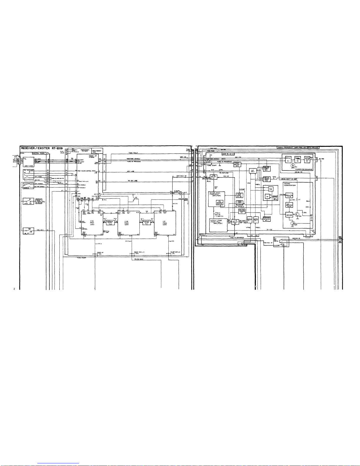
Schematic diagrams contain pertinent voltage and waveform reference data to assist in fault isolation and are used an conjunction with the performance test flowcharts.
Component location diagrams locate and list every replaceable component, and identify the location of test points and pins required to monitor voltages and waveforms on performance test flowcharts.
Test and alignment setup diagrams provide a list of test equipment, a list of special tools and materials, fabricated cables and fixtures, and initial connections for the test setup, They are used in conjunction with the performance test flowcharts. Module
performance tests may be performed more easily if the module is tested while inside the radio set, rather than extended via cables. Once a fault is indicated, the module should be removed from the radio set and connected via appropriate extender cables.
Performance test flowcharts provide performance test (heavy flow line) and troubleshoot mug procedures (light flow line) for fault isolating to a component or group of components. The flowcharts are supported by the reference information provided in the
other diagrams.
Alignment procedures are used in conjunction with the performance test flowcharts.
NOTE
Poor electrical connection due to dirty or bent connector plus may often be the cause of equipment malfunction or faulty test indication. All electrical connections should be double-checked before proceeding with test or fault isolation.
TECHNICAL CHARACTERISTICS
Characterlstlc Description
RADIO SET AN/PRC-104 (Radio Set)
Frequency Range 2.0000 to 29.9999 MHz in. 0.0001 MHz
(100 Hz) increments (280,000 possible
frequency settings)
Frequency Accuracy ±1 ppm for -51°F (-46°C) to +160°F (+71°C)
(±2 to 30 Hz of setting) from 2 to 30 MHz
respectively.
Operating Modes - Slngle sideband (selectable USB or LSB)
- Voice/cw (Morse or burst cw at 300 wpm)
- Data (FSK or DPSK up to 2400 bps) compatible
with 75 baud military teletype
- Receive only (inhibits transmit operation)
Audio Input Impedance 150 ohms, -56 dbm (voice) or, 6 mv. RMS.
and Level 600 ohms, 0 dbm (data) or, 77 v. RMS,
RP Output Power 20w (PEP), 0.25w (PEP) exciter output
RF Output Impedance 50-ohms, unbalanced. Output protected to
infinite VSWR due to antenna short or open.
Antenna Tuning Automatic to 1.5:1 VSWR (3 seconds
tuning time, typical)
Characteristic Description
Power Requirements 20.0 to 32.0 vdc with input at 3.5 amp
(24 vdc) for transmit (typical). 200 ma
for receive (typical).
Operating Temperature Range -51°F (-46°C) to +160°F (+71°C)
Environmental Meets applicable provisions of MIL-
STD-810B
Mean Time Between Failure (MTBF) 2500 hours (demonstrated per MIL-
STD-785)
Mean Time to Repair (MTTR) 15 minutes (module replacement)
Dimensions 12 1/2 x 10 1/2 x 2 5/8 (31.75 cm x
26.67 cm x 6.66 cm) D x U x H
Weight 14 pounds (6.36 Kg), including 4.8 AN
silver zinc battery (without
accessories)
RECEIVER
Sensitivity
SSB, Cal, FSK 0.7 v for 10 db SINAD (-110 dbm
voice, -70 dbm data)
Selectivity 2.5 kHz Bandwidth at -3 db
SSB, CW, FSR 6.0 kHz Bandwidth at -60 db
Image Rejection 70 db
I.F. Rejection 60 db
Audio Output 25 tow into 500 (nominal)
Characteristic Description
Audio Distortion 5 percent at 5 mw, 350 to 3000 Hz
Desensitization (signal to ±2.5% to -29 dbm;
degrade SINAD 3 db) ±10% to -15 dbm;
±50% to +17 dbm
TRANSMITTER
RF Output Power 0.3 W (PEP) for RT-1209, 20W (PEP or
average) with AM-6874
Intermodulation Distortion (IMD) -25 db (two equal tones at rated output
power
Harmonic Radiation -50 db
Carrier Suppression -42 db
Unwanted Sideband Suppression -45 db
All Other Spurious -45 to -60 db
Duty Cycle 1 minute continuous keydown, 9:1
transmit/receive ratio
BATTERY PACK
Battery Silver-zinc (AgZn), rechargeable 4.8 AH
1

TM 11-5820-919-40-2
Figure 1-1. Radio Set Block Diagram (Sheet 1 of 2)
2

TM 11-5820-919-40-2
Figure 1-1. Radio Set Block Diagram (Sheet 2 of 2)
3

TM 11-5820-919-40-2
Figure 1-2. Radio Set Power Distribution
4

TM 11-5820-919-40-2
SPECIAL TOOLS, MATERIALS, AND FABRICATED TEST CABLES AND FIXTURES
Description Part Number Reference
Audio Input/Keying Adapter ... Figure 3-11C
Whip Adapter ... Figure 3-11D
Kit, Tool, Electrons TK-100/G None
Bench Repair Center Pace PRC-350C None
Maintenance Kit, Printed Circuit MK-984/A None
NOTE: Referenced figures are in TM 11-5820-919-40-1.
TEST EQUIPMENT
Name Designation Quantity
Audio Oscillator AN/URM-127 1
VTVM AN/USM-116 1
Dummy Load (50 ohm) DA-553( )/4 1
Signal Generator, RF AN/USH-323 1
Digital Multimeter AN/USM-341 1
(DVM, oh meter function)
Attenuator, Step CN-1128/U 1
10-db steps, 0.5w, 50 ohm
Watt Meter, RF
- Power Meter Hewlett Packard HP-435A 1
- Thermocouple Power Hewlett Packard HP-8482A 1
Sensor
Spectrum Analyzer Hewlett Packard HP-141-T 1
- High Resolution Hewlett Packard HP-8552B 1
IF Section
- RF Section Hewlett Packard HP-8553B 1
- Tracking Generator Hewlett Packard HP-8443A 1
Attenuator, Coaxial Narda 765-20 1
Power Supply, DC Hewlett Packard HP-6439B 1
Figure 1-3. Radio Set Performance Test Setup
5

TM 11-5820-919-40-2
RADIO SET PERFORMANCE TEST
NOTE 1: Radio Set RF Signal Generator
Frequency (kHz) Sideband Frequency (MHz)
No. 1. a. 2,221.0 USB 2.2220
b. 2,221.0 LSB 2.2200
No. 2 a. 3,334.0 USB 3.3350
b. 3,334.0 LSB 3.3330
No. 3 a. 6,665.0 USB 6.6660
b. 6,665.0 LSB 6.6640
No. 4 a. 8,889.0 USB 8.8900
b. 8,889.0 LS 8 .8880
No. 5 a. 15,554.0 USB 15.5550
b. 15,554.0 LSB 15.5530
No. 6 a. 27,778.0 USB 27.7790
b. 27,778.0 LSB 27.7770
NOTE 2: Harmonic filter bands are 2-3 MHz, 3-5 MHz, 5-8 MHz, 8-12 MHz, 12-20 MHz, and 20-30 MHz.
NOTE 3: For a thorough test, use all the test frequencies listed in Note 1 on USB only.
NOTE 4: Frequency must be changed each tine to cause tune-up tone when PIT is closed.
NOTE 5: See page 8.
Figure 1-4. Radio Set Performance Test (Sheet 1 of 2)
6

TM 11-5820-919-40-2
Figure 1-4. Radio Set Performance Test (Sheet 2 of 2)
7

TM 11 5820-919-40-2
NOTE 5. SPURIOUS RECEIVE SIGNALS
1. A spurious receive signal is an audio tone heard in the handset in receive when no tone should be present (i.e., no
signal present at the antenna connector). These signals are produced as a result of interaction (harmonic crossover)
between the first and second local oscillators. Military specifications for this radio set permit a maximum of 200
spurious signals to be generated within the frequency synthesizer, A1A3, without adversely affecting the radio set's
acceptability. Table A lists those frequencies at which acceptable spurious signals may be encountered in some
radio sets. In addition to those frequencies listed in table A are the fundamental of the 5 MHz local oscillator (see
frequency [sited on case of 5 MHz L.O., A1A3U1).
2. Use of table A: For each frequency listed at which acceptable spurious signals may be encountered, there are
several dial frequencies at which audible tones may be heard.
Example: Internally generated spurious signal at 13.5000 MHz.
a. With a dial frequency of 13,501.0KHz, LSB selected, the audio tone produced would be 1.0 KHz.
b. With a dial frequency of 13,498.6~Bz, USB selected, the audio tone produced would be 1.4 KHz.
TABLE A
FREQ (MHz) FREQ (MHz) FREQ (MHz) FREQ (MHz) FREQ (MHz)
2.2222 5.6250 12.0833 17.7777 25.3571
2.5000 5.7143 12.5000 17.9167 25.4167
2.9412 5.8000 12.7273 17.9169 25.5555
3.0555 5.8333 12.8125 18.6666 25.6250
3.1250 6.0000 12.9167 18-7500 25.7143
3.3333 6 1338 13.1250 18.8235 26.0000
3.4375 6 2500 13.3333 18.8888 26.2500
3.5294 6.6666 13.5000 19.0909 26.3636
3.7500 7.0833 13.6111 19-1666 26.6666
4.0000 7.2727 13.6364 19.6429 26.9231
4.0625 7.5000 13.7500 20.0000 27.1429
4 1666 7.6471 14.0000 20.3125 27.2727
4 2857 7 8125 14.1176 20.3571 27 5000
4.3750 8 0000 14.2857 20.5000 27 6923
4.4444 8.1818 14.3750 20.6250 28.2143
4.5000 8.6375 14.4444 20.6666 28.5000
4.5455 8.5000 14.5455 20.9091 28.5714
4.5833 8.6666 14.6875 21.3333 28.7500
4.6154 8.9474 14.7059 21.5000 29.1666
4 6429 9.1666 15.3125 21.5385 29.2308
4 6666 9 3333 15.3333 21-7857 29.3750
4.6875 9 5000 15.3571 21.8750 29.5000
4 7059 9.6429 15.5000 22.0000 29.5833
4 7222 9 6875 15.6250 22.2222 29.9999
4.7368 9 7222 15.7141 22.3077
5 2632 10.0000 15.7143 22.5000
5 2777 10.3125 16.0000 23.0769
5.2941 10.3371 16.0714 23.3333
5.3125 10 6666 16.1538 23.5000
5.3333 10 7692 16.5000 23.7500
5.3571 11.0714 16.6000 23.8462
5.3846 11.1111 16.7857 24.0000
5 4167 11.2500 16.9231 24.2857
5 4545 11 5385 17.1429 24.3750
5.5000 11 8182 17.5000 24.5833
5.5555 11.8750 17.6923 24.6875
8

Figure 2-1. Receiver/Exciter A1 Interconnection Schematic
9
TM 11-5820-919-40-2

TM 11-5820-919-40-2
Figure 2-2. Receiver/Exciter A1 Component Location (Sheet 1of 2)
10

TM 11-5820-919-40-2
ITEM DESCRIPTION ITEM DESCRIPTION
1. Cover Assembly 23. Multipin Connector
2. Screw, Captive A1A4P1
(8 places) 24. Captive Allen Screw
3. Screw, Captive (2 places)
(4 places) 25. Printed Wiring Board
4. Harmonic Filter 26. Ribbon Cable Assembly
Module A1A2 27. RF Cables A1A2J2(W1)
5. Multipin Connector A1A2J1(W1),
(Harmonic Filter A1A2J3(W1),
Module) A1A2P1 A1A2J4(W1)
6. RF Cables 28. Mount mug Nut (2 places)
A1A2J1(W1P4),1 29. Jack Receptacle
A1A2J2(W1P3) Connector J1
7. Control Panel cover 30. Packing, Preform
Assembly (Face) A1A4 31. Connector, Plug (Multipin)
8. Receiver/Exciter A1 A1A4P1
9. RF Cables A1A3J3(W4), 32. Mounting Screw
A1A3J4(W1P5), (2 places)
A1A3J2(W2), 33. Multipin, Connector,
A1A3J1(W3) A1A2J4
10. Synthesizer Module A1A3 34. Ribbon Cable Assembly
11. Screw, Captive A1W1
(5 places) 35. Packing, Preform
12. Cover, Assembly 36. Connector, Stud
13. Screw, Captive 37. Multipin Connector
(8 places) A1A3J3
14. Screw, Captive 38. Mounting Screw
(4 places) (2 places)
15. Power Supply Module 39. Mounting Screw)
A1A5 (2 places
16. Multipin Connector 40. Multipin Connector
A1A5P1 A1A1J2
41. Ribbon Cable Assembly
17. RF Cables A1A1J1(W2), A1W1
A1A1J2(W3), 42. Circuit Board Mounting
A1A1J3(W1P2), Screws, A1len
A1A1J4(W4) (4 places)
18. Modulator/Demodulator 43. .020” C Spring Clip
Module A1A1 (22 places)
19. Screw, Captive
(4 places) DISASSEMBLY NOTE
20. Multipin Connector
A1A1P1 When disassembling radio or
21. Audio Connector Plugs modules for the first time it may
A1A4J1, J2 be necessary to heat screws to
22. Screw, Captive loosen the loctite compound
(6 places) applied at the factory
TM-07748A-45/3 Figure 2-2. Receiver/Exciter A1 Component Location (Sheet 2 of 2)
ITEM DESCRIPTION
1Printed Wiring Board
J5 Connector, Receptacle
CR7 Diode
2Lead Socket
3Fuse, Instr
CR5 Diode
CR6 Diode
CR2 Diode
CR1 Diode
CR8 Diode
CR4 Diode
CR3 Diode
11

TM 11-5820-919-40-2
SPECIAL TOOLS, MATERIALS, AND FABRICATED TEST CABLES AND FIXTURES
Description Part Number Reference
Audio Input/Keying Adapter ••• Figure 3-11C
Lip Adapter ••• Figure 3-11D
Kit, Tool, Electronic TK-100/G None
Bench Repair Center Pace PRC-350C None
Maintenance Kit, Printed Circuit MR-984/A None
NOTE: Referenced figures are in TM 11-5820-919-40-1.
TEST EQUIPMENT
Name Designation Quantity
Radio Set, Test Bed AN/PRC-104 1
Audio Oscillator AN/URM-127 1
VTVM AN/USM-116 1
Dummy Load (50 ohm) DA-553( )/4 1
Signal Generator, RF AN/USM-323 1
Digital Multimeter AN/USM-341 1
(DVM, ohmmeter function)
Attenuator, Step CN-1128/U 1
10-db steps, 0.5w, 50 ohm
Watt Meter, RF
- Power Meter Hewlett Packard HP-435A 1
- Thermocouple Power Hewlett Packard HP-8482A 1
Sensor
Spectrum Analyzer Hewlett Packard HP-141-T 1
- High Resolution Hewlett Packard HP-8552B 1
IF Section
- RF Section Hewlett Packard HP-8553B 1
- Tracking Generator Hewlett Packard HP-8443A 1
Power Supply, DC Hewlett Packard HP-6439b 1
Attenuator, Coaxial Narda 765-20 1
20 db, 30w min., 50 ohm
12
Figure 2-3. Receiver/Exciter A1 Performance Test Setup
Table of contents