Lord MicroStrain 3DM-GX4-25 User manual

LORD USERMANUAL
3DM-GX4-25™
Miniature Attitute Heading Reference System (AHRS)

© 2014 LORDCorporation
MicroStrain®Sensing Systems
459 Hurricane Lane
Suite 102
Williston, VT 05495
United States of America
Phone: 802-862-6629
Toll Free: 800-449-3878
Fax: 802-863-4093
http://www.microstrain.com
sensing_support@LORD.com
sensing_sales@LORD.com
Copyright © 2014 LORD Corporation
IEPE-Link™, Torque-Link™, 3DM-RQ1™, Strain Wizard®, DEMOD-DC®, DVRT®, DVRT-Link™, WSDA®, HS-
Link®, TC-Link®, G-Link®, V-Link®, SG-Link®, ENV-Link™, Watt-Link™, Shock-Link™, LXRS®, Node
Commander®, SensorCloud™, Live Connect™, MathEngine®, EH-Link®, 3DM®, FAS-A®, 3DM-GX1®, 3DM-
GX3®, 3DM-GX4™, 3DM-DH®, 3DM-DH3™, EmbedSense®, MicroStrain®, and Little Sensors, Big Ideas.®are
trademarks of LORD Corporation.
Document 8500-0047 Revision A
Subject to change without notice.

3DM-GX4-25™Attitute Heading Reference System User Manual
Table of Contents
1. System Overview 6
2. Sensor Overview 7
2.1 Components 8
2.2 Interface and Indicators 9
3. Basic Setup and Operations 10
3.1 Software Installation 11
3.2 System Connections 12
3.3 Software Interface 13
3.3.1 Interactive Help Menu 13
3.4 Sensor Communication 14
3.5 Sensor Settings 15
3.5.1 Saving Configurations 17
3.6 Data Monitoring and Recording 18
3.7 Viewing Data 21
4. Sensor Measurements 22
4.1 Direct Sensor Measurements (IMU Outputs) 23
4.2 Computed Outputs (Estimation Filter/AHRS) 25
4.3 Sensor Reference Frames 28
4.3.1 Geodetic Frame 28
4.3.2 NorthEast Down (NED) Frame 29
4.3.3 Sensor Frame 30
4.3.4 Platform Frame 31
5. Performance Optimization 33
5.1 Magnetometer Calibration 33

3DM-GX4-25™Attitute Heading Reference System User Manual
5.2 Gyroscope Bias 36
5.3 Heading Drift and Compensation 37
5.4 Angular Rate and Acceleration Limits 38
5.5 Bandwidth 38
5.6 Platform Frame Transformation 38
5.7 Estimation Filter Operation 38
5.8 Estimation Filter Convergence 40
5.8.1 Initial Convergence 40
5.8.2 Bias Convergence 40
5.8.3 Output Uncertainty 40
5.9 Vibration Isolation 41
5.10 IMU Sensor Calibration 41
5.11 Temperature Compensation 41
6. Sensor Installation 42
6.1 Sensor Mounting 42
7. OEMSystemIntegration 43
7.1 DataCommunications Protocol (DCP) 43
7.1.1 Packet Builder 44
7.1.2 Sensor Direct Mode 45
7.2 Sensor Wiring 46
7.3 Sampling on Start-up 47
7.4 Connecting to a Datalogger 47
7.5 Using Wireless Adapters 47
8. Troubleshooting 48
8.1 Troubleshooting Guide 48
8.2 Repair and Calibration 52

3DM-GX4-25™Attitute Heading Reference System User Manual
8.3 Technical Support 53
9. Maintenance 54
10. Parts and Configurations 55
10.1 Standard Configurations 55
10.2 Accessories 57
10.3 Warranty Information 58
10.4 Sales Support 59
11. Safety Information 60
12. References 61
12.1 Reference Documents 61
12.2 Glossary 62

3DM-GX4-25™Attitute Heading Reference System User Manual System Overview
6
1. System Overview
The LORD MicroStrain®3DM-GX4™family of industrial grade inertial sensors provides a wide
range of triaxial orientation measurements and computed navigation solutions. In all models, the
Inertial Measurement Unit (IMU) includes direct measurement of acceleration, angular rate, and
atmospheric pressure. Sensor measurements are processed through an Extended Kalman Filter
(EKF) to produce high accuracy computed outputs. The computed outputs vary between models
and include: pitch and roll in the 3DM-GX4-15™model, the full attitude solution (pitch, roll, and
yaw) in the 3DM-GX4-25™AHRS model, and the full PVA (position, velocity and attitude) solution
in the 3DM-GX4-45™GPS-INS model. The Kalman filter provide Adaptive EKF technologies to
compensate for magnetic and linear acceleration anomalies, as applicable to the model. It also
provides sensor bias tracking, auto-zero update options (ZUPT), and user adjustable sensor noise
factors. All sensors are fully temperature compensated and calibrated over the full operating
temperature range
The use of Micro-Electro-Mechanical System (MEMS) technology allows for small, lightweight
devices. Sensors are integrated into customer systems using serial communication protocols such
as RS232 and USB. The LORD MicroStrain ®MIPMonitor software can be used for device
configuration, real time measurement monitoring, and data recording. The LORD MicroStrain®
MIPData Communications Protocol that is used to communicate with LORD MicroStrain®inertial
sensors is also available for users who want to develop customized software solutions. Because of
the unified set of commands across the sensor family, it is easy to migrate code from one inertial
sensor to another.
Common applications of LORD MicroStrain ®inertial sensor products include vehicle health
monitoring, platform stabilization, down- hole and drilling operations, and inertial navigation
systems such as unmanned air and ground vehicles and personal navigation systems.

3DM-GX4-25™Attitute Heading Reference System User Manual Sensor Overview
7
2. Sensor Overview
The 3DM-GX4-25™is a high-performance, miniature Attitude Heading Reference System
(AHRS) that combines micro inertial sensors for use in a wide range of industrial grade
applications such as unmanned vehicle navigation, robotic control, platform stabilization, motion
tracking and analysis, vehicle health monitoring, and device aiming.
The 3DM-GX4-25™utilizes the strengths of integrated multi-axis gyroscopes, accelerometers,
and magnetometers in combination with temperature, and pressure readings to provide high
accuracy attitude (including heading), and inertial measurements. Each of the integrated sensors
is especially good at certain tasks, and it is the weighted combination of their outputs that provides
the best estimations for attitude. All sensor measurements are temperature compensated and are
mathematically aligned to an orthogonal coordinate system. The combination of sensors,
environmental compensation and dual on-board processing with an Adaptive Kalman Filter (AKF)
allow the 3DM-GX4-25™to perform well in a wide variety of applications that require low noise,
drift, gain, and offset errors. Uncertainty monitoring, and bias estimation outputs are available, and
settings for sensor filtering, sensor noise, sensor bias, and more offer many adjustments for
specific application needs.
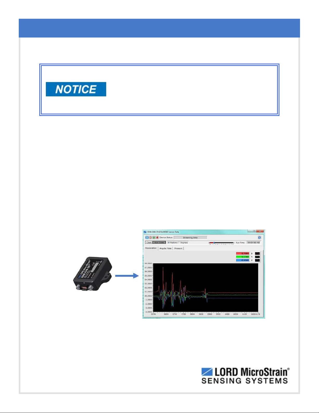
The 3DM-GX4-25™communicates through a serial communications cable and is monitored by a
host computer. Sensor measurements and computed outputs can be viewed and recorded with
the LORD MicroStrain®MIPMonitor software that is provided with system starter kits, and also
available as a free download from the LORD MicroStrain®website. Alternatively, users can write
custom software with the LORD MicroStrain®open source data communication protocol. The
data is time-aligned and available by either polling or continuous stream.
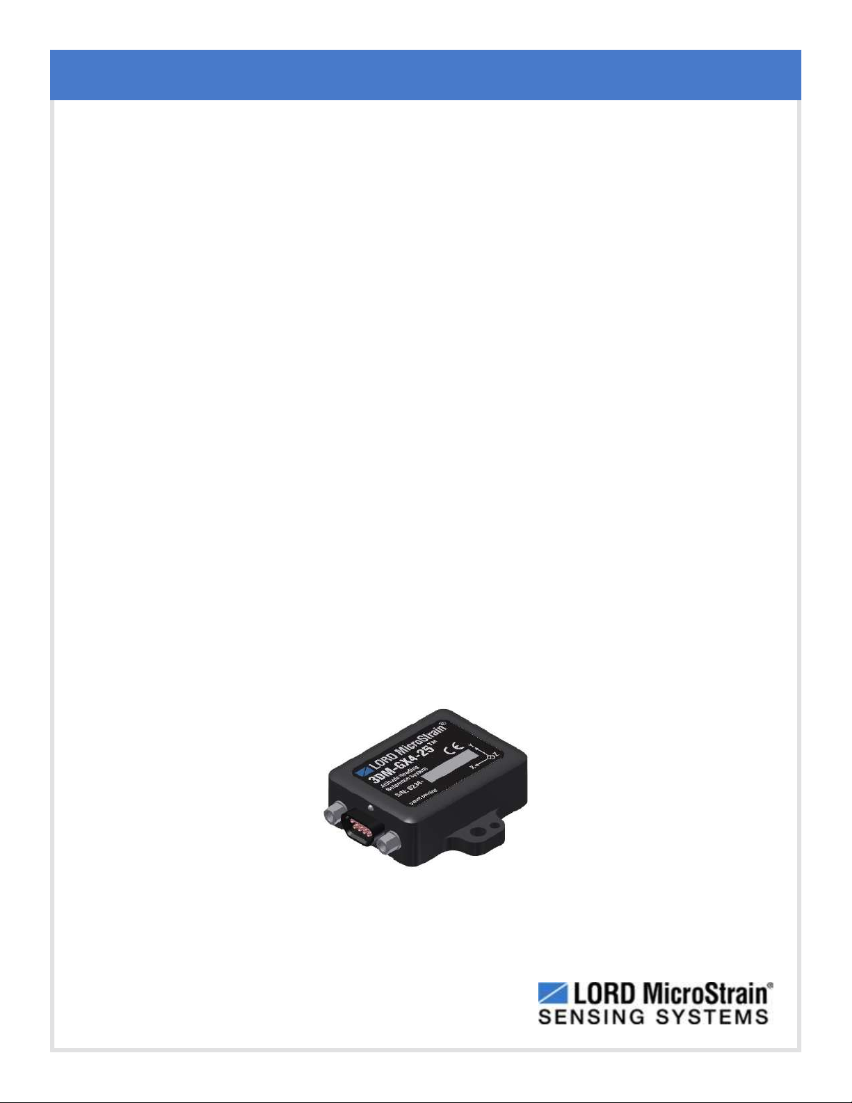
Figure 1 - 3DM-GX4-25™Sensor

3DM-GX4-25™Attitute Heading Reference System User Manual Sensor Overview
8
2.1 Components
The 3DM -GX4 -25™can be purchased by itself or in a starter kit that includes everything
needed to begin using it. The starter kits include the 3DM-GX4-25™inertial sensor, a serial
communications cable (either RS232 or USB), a power supply with country plug adapter
(RS232 kits only), and all software, drivers, and documentation. This manual covers all items
included in the starter kits. For a complete list of available configurations, accessories,
additional system products and ordering information see Parts and Configurations on page 55.
Item Description Quantity
A3DM-GX4-25™Inertial Sensor 1
BCommunications cable (USB or RS232) 1
CPower supply and country plug adapters (for RS232 only) 1
-- MIPMonitor Software Suite 1
-- User Manual, Quick Start Guide and Calibration Certificate 1
Table 1 - Components List

3DM-GX4-25™Attitute Heading Reference System User Manual Sensor Overview
9
2.2 Interface and Indicators
The 3DM-GX4-25™sensor interface is a dual use communications and power input connector.
The sensor is mounted using the mounting and alignment holes as needed (see Sensor
Mounting on page 42).
The indicators on the 3DM - GX4 - 25 ™include a device status indicator and the device
information label. Table 2 - Indicator Behaviors describes the basic status indicator behavior.
The device information label includes the sensor frame diagram (axis orientation) which will be
critical during device installation (see Sensor Frame on page 30).
Figure 2 - Interface and Indicators
Indicator Behavior Device Status
device status
indicator
OFF no power applied
rapid flash streaming data
slow pulse idle mode, awaiting commands
Table 2 - Indicator Behaviors

3DM-GX4-25™Attitute Heading Reference System User Manual Basic Setup and Operations
10
3. Basic Setup and Operations
Do not bring the inertial sensor into contact or close proximity
with magnets. Magnets may disrupt the sensor operation and
cause magnetization of internal components, which can
affect magnetometer performance. If magnetization is
suspected, use a degaussing tool to demagnetize.
To acquire sensor measurements and computed outputs, the 3DM-GX4-25™is used with a host
computer capable of serial communication, and a software interface. The LORD MicroStrain®
MIPMonitor software is provided with the system and includes all functions needed for sensor
configuration and data acquisition. Users may also utilize the LORD MicroStrain ®MIPData
Communications Protocol to write custom software applications with expanded or specific feature
sets needed for the application. MIPMonitor includes a message building tool that can be used to
streamline this process. For more information see OEMSystemIntegration on page 43.
In this section hardware and software setup is described, including an overview of the MIPMonitor
software menus required to configure a sensor and begin data acquisition. It is intended as a quick
start guide and is not a complete demonstration of all system or software features and capabilities.
Figure 3 - Acquiring Sensor Data with MIPMonitor

3DM-GX4-25™Attitute Heading Reference System User Manual Basic Setup and Operations
11
3.1 Software Installation
NOTE
The MIPMonitor Software Suite includes hardware drivers required for all
3DM-GX4™sensors. Sensors will not be recognized without these drivers.
To install MIPMonitor Software Suite on the host computer, complete the following steps:
1. Launch the software installation menu by inserting the software CD or thumb drive
into the host computer or by running the Autorun.exe file from the software directory
in Windows®Explorer.
2. In the software installation menu select Install MIPMonitor Software and follow the on
screen prompts to completion.
3. If the sensor has internal magnetometers, select Install MIP Hard and Soft Iron
Calibration Software and follow the on screen prompts to completion. This is used for
magnetometer field calibration.
4. Select Install Inertial Drivers to install the hardware drivers required for operating the
sensors, and follow the on screen prompts to completion.
5. Install Inertial Manuals, if desired, and reboot the host computer.
Figure 4 - Software Installation Menu

3DM-GX4-25™Attitute Heading Reference System User Manual Basic Setup and Operations
12
3.2 System Connections
Power is applied to the sensor either through a host computer
USB port or an external power supply, such as the one
provided in the RS232 starter kit. Use only power supplies
within the operating range of the sensor or damage or injury
could result. Once power is applied the sensor is on and
active.
To acquire sensor data the following components are needed: 3DM- GX4 - 25 ™sensor,
communication cable, power cable, as applicable for RS232 communications, and a host
computer with access to the data acquisition software, such as LORD MicroStrain ®
MIPMonitor.
Figure 5 - System Connections

3DM-GX4-25™Attitute Heading Reference System User Manual Basic Setup and Operations
13
3.3 Software Interface
The MIPMonitor software includes a main window with system information and menus, a
device settings window ( see Sensor Settings on page 15 ), and several data monitoring
windows (see Data Monitoring and Recording on page 18).
The main window provides an overview of connected devices. Devices are selected by clicking
on them. A device menu is available by right clicking on the device name, and includes the most
used items from the header row menus ( Figure 6 - Main Window ). The header row menu
includes selections for data sampling, recording, device settings, opening windows, selecting
which open window to view, and advanced features such as selecting the communications
mode. The icon toolbar includes buttons for help menu access, device refresh, and data
sampling and recording (see Data Monitoring and Recording on page 18).
Figure 6 - Main Window
3.3.1 Interactive Help Menu
MIPMonitor also features context-sensitive help menus that provide explanations of the
information and settings as they are hovered over with the computer cursor. This feature is
enabled by selecting the question mark icon or Help button in any window.
Figure 7 - Context Sensitive Help Menu

3DM-GX4-25™Attitute Heading Reference System User Manual Basic Setup and Operations
14
3.4 Sensor Communication
Once power has been applied to the sensor, it is on. The sensor selects the appropriate serial
communication (USB or RS232) on power- up based on which cable is connected. If the
hardware drivers have been installed, communication can be established using the
MIPMonitor software interface.
1. Verify the sensor device status indicator is on.
2. Open the MIPMonitor software.
3. The sensor should appear in the device list automatically when the software is
opened, and includes the device information and communication port assignment
(Figure 8 - Sensor Communication ). If it is not automatically discovered, use the
refresh button to search for the sensor.
Figure 8 - Sensor Communication
NOTE
If data is not actively being exchanged between the sensor and host computer
the status message may display Not Connected. This indicates the port status,
not the sensor availability. When commands are sent to the sensor, the
software will automatically connect to it before sending the message.

3DM-GX4-25™Attitute Heading Reference System User Manual Basic Setup and Operations
15
3.5 Sensor Settings
Device settings are stored in the sensor memory. Only the configuration options that are
available for the type of sensor being used will be available in the configuration menus.
To enter the settings menu, right-click on the sensor name, and select Device Settings from the
menu (Figure 9 - Device Settings Menu).
NOTE
When selecting sensor and estimation outputs to be recorded,
communications bandwidth considerations should be taken into account,
especially when using RS232 communications. Lower baud rates equate to
lower communications bandwidth which can be consumed quickly by selecting
a large number of measurements at high sample rates. Overrunning the
communications bandwidth will result in dropped communications packets and
lost data.
1. The following describes the Device Settings interface:
a. Main menu tabs: The main tabs break up the setting into broad
functional groups for the types of measurement available. For the 3DM-
GX4-25™these will include calculated measurements (Estimation Filter),
and direct inertial sensor measurements (IMU).
b. Message Format (first sub-menu tab): Under each main menu tab
there are additional sub-menu tabs, including the Message Format tab.
The Message Format tabs allows the user to select the measurement type
to be displayed and recorded (b1), and the data rate (rate at which data is
sent to the host computer) in samples/second (b2).
c. Measurement parameters (other sub- menu tabs): Available sub-
menu tabs besides the Message Format tab depend on the selected main
menu tab. These tabs include the configurable settings for each
measurements.
d. Scrolling: used to navigate to additional sub-menus.

3DM-GX4-25™Attitute Heading Reference System User Manual Basic Setup and Operations
17
3.5.1 Saving Configurations
Sensor settings are saved temporarily in the device memory by selecting the OK button in
the Device Setup window. To save the settings for future use, select Settings > Save
Current Settings from the main window (Figure 10 - Save Sensor Settings). If the settings
are not saved in this manner they will be lost when the sensor is powered off. If the sensor
settings are saved as described, the setting will remain intact when the sensor is powered
on again.
Previously saved settings can be recalled by selecting the sensor in the device list and the
selecting Settings > Load Startup Settings.
Figure 10 - Save Sensor Settings

3DM-GX4-25™Attitute Heading Reference System User Manual Basic Setup and Operations
18
3.6 Data Monitoring and Recording
NOTE
During viewing and recording, only the outputs that are selected in the
Message Format tabs in the Device Setup menu are displayed and recorded
(see Sensor Settings on page 15).
Throughout the MIPMonitor menus the same icons are used to control data streaming
(sampling) and recording, shown in Table 3 - Sampling and Recording Controls. These icons
can be found in the MIPMonitor main window icon toolbar and in each data monitoring window.
The same commands are also found in the main window Control menu.
Figure 11 - Main Window Controls
Icon Command
Run: start data streaming
Stop: end data streaming
Step: sample single set of data
Record: start and stop data recording
Table 3 - Sampling and Recording Controls

3DM-GX4-25™Attitute Heading Reference System User Manual Basic Setup and Operations
19
There are several data monitoring views available depending on what measurements are
desired for monitoring and recording. Each view corresponds to one of the main categories in
the Device Settings window. For example, the 3DM - GX4 - 25 ™includes Sensor Data
Monitoring for the IMU measurements, GPS Monitoring for the GPS metrics, and
EFMonitoring for the Estimation Filter outputs (Figure 12 - Data Monitoring and Streaming ).
During viewing and recording only the outputs that are selected in the Message Format tab of
the Device Settings menu are displayed and recorded (see Sensor Settings on page 15).
Data streaming must be started before data can be recorded, however it is not necessary to be
viewing it in a data monitoring window. Data monitoring is used primarily to confirm the system
is operating correctly or to view the outputs in near real time. If sensor setup has already been
confirmed, streaming and recording can be initiated from the main window.
Figure 12 - Data Monitoring and Streaming is an example of Sensor Data Monitoring, which
displays the selected IMU measurements. In data monitoring windows, no data will be
displayed until data streaming is started, and no data will be recorded (even if it is being viewed)
until data recording is initiated (armed). In this example, the y-axis of the graph indicates data
points and the x-axis is the measurement units, and there is a tab for each measurement.
1. Right-click on the device in the main window and select SensorData Monitoring.
2. Press the Start Streaming icon to start sampling.
Figure 12 - Data Monitoring and Streaming

3DM-GX4-25™Attitute Heading Reference System User Manual Basic Setup and Operations
20
3. To record data, select the Arm Recording icon at any time.
4. Select the type of data file to generate, Binary or CSV.The CSV file is the most
common and can be viewed and processed by data editors such as Microsoft Excel ®.
NOTE
If the data is recorded in Binary format it will require a translation program that
utilizes the LORD MicroStrain®MIPData Communications Protocol to make it
user-readable.
Figure 13 - Record Data
5. To end recording press the Arm Recording button again, and select OK to the
confirmation prompt.
6. Select the Stop Streaming icon to end sampling.
7. Use the red "X" in the upper right of the sensor monitoring window to exit the
monitoring mode.
Table of contents
Other Lord MicroStrain Measuring Instrument manuals