82344-01 Eccentricity Monitor Operation
2MONITORFUNCTIONS SHEET 1OF 2
ECCENTRICITY -Eccentricity (ECC) is defined as the variation between the outer diameter of a shaft surface and
the true geometric center line of the shaft. This variation, cAled shaft bow, can be a fixed mechanical bow, a tem-
porary thermal or gravity bow, or some combination of each. The. Eccentricity Monitor measures shaft bow using the
input from an eccentricity transducer and a Keyphasor source.
DIRECT AND PEAK TO PEAK -The input signal to the monitor from the eccentricity transducer is split into two
channels designated as Direct and Peak to Peak channels.
KEYPHASOR - The Keyphasor (KO) input is defined as a once-per-shaft-revolution event indicator. The monitor can
be programmed to accept the input from a Keyphasor signal routed directly to the monitor through the Signal Input
Module, or from either one of two Keyphasor input signals routed to the monitor through the System Monitor and a
Keyphasor bus on the system backplane. If these external Keyphasor signals are not available, the monitor can be
programmed to use an internal, simulated Keyphasor signal.
KEYPHASOR THRESHOLD VOLTAGE AND HYSTERESIS - The Keyphasor threshold voltage can be programmed
for automatic or manual mode, and the Keyphasor hysteresis is jumper selected. For a description of Keyphasor
threshold voltage and hysteresis refer to Eccentricity Monitor Maintenance Manual, Part No. 82345-01.
ECCENTRICITY OK - When the eccentricity transducer signal is within its upper and lower OK limits, the transducer
is defined as OK. The eccentricity OK detection circuit controls the ECC OK LED and the monitor relay drive to the
OK Relay.
KEYPHASOR OK - The Keyphasor (KO OK) LED goes on if the Keyphasor input is within 1 to 600 RPM, and if the
change in rpm between consecutive cycles is not greater or less than 50%. If the Keyphasor input goes NOT OK, the
peak to peak channel is clamped to zero.
TIMED OK/MONITOR DEFEAT -Timed OK/Monitor Defeat prevents faulty transducer wiring from causing false
alarms. If the eccentricity input signal level is not within the upper and lower OK limits, the ECC OK LED goes off,
the BYPASS LEDs go on, the Direct and Peak to Peak channels are disabled, and the OK Relay deenergizes. If the
eccentricity input signal level is restored within the upper and lower OK limits for 60 seconds, the ECC OK LED starts
flashing at 1 Hz to indicate the OK state is restored, the BYPASS LEDs go off, and monitoring is enabled. The
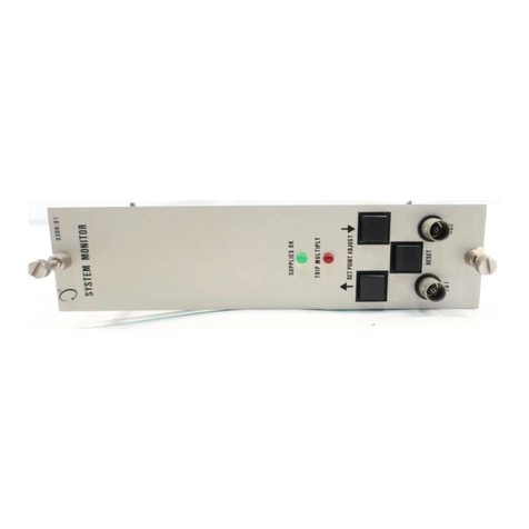
RESET switch on the front panel of the System Monitor must be pressed to stop the ECC OK LED from flashing (it
remains on). If the eccentricity channel remains in the NOT-OK state, the MONITOR BYPASS switch on the
monitor circuit board can be set to put the monitor out of service. Without this feature. the OK Relay could not be
reactivated. When Timed OK/Monitor Defeat Mode is selected, the NOT-OK Nonlatching Mode must be selected.
The recorders and communication processor output signals are clamped to zero scale, and the LCD display registers
zero if the transducer is NOT OK.
OK RELAY -The OK Relay is located on the Power Input Module. Every channel in the rack must be OK or
bypassed to energize the OK Relay.
DIRECT ALARM ENABLED/DISABLED -Direct Eccentricity can be programmed for alarm enabled or disabled. If
the disabled option is selected, Direct Eccentricity is still displayed on the LCD display, but the alarm setpoints are not
used.
FIRST OUT - Separate First Out circuits exist for Alert and Danger alarms. A monitor with First Out option selected
flashes a channel alarm LED if that monitor channel is the first in the rack to go into alarm. Pressing the RESET
switch acknowledges the First Out.
MONITOR BYPASS AND DANGER BYPASS -The monitor can be bypassed by setting the Monitor Bypass switch on
the monitor circuit board. When the switch is set, the OK LEDs go off and the BYPASS LEDs come on. Bypassing
the monitor in the NOT-OK state will clear the OK relay drive signal. For maintenance functions, a Danger Bypass
switch on the monitor circuit board is set to inhibit the Danger relay drive. This also turns on the BYPASS LEDs.
Other front panel functions are not affected. The Danger Bypass function can be enabled with a programming jumper.
2


