Lord MicroStrain 3DM-CX5-10 User manual

LORD USER MANUAL
3DM®-CX5-10
Inertial Measurement Unit (IMU)

MicroStrain®Sensing Systems
459 Hurricane Lane Suite 102
Williston, VT 05495
United States of America
Phone: 802-862-6629
www.microstrain.com
Copyright © 2018 LORD Corporation
3DM®, 3DM-DH®, 3DM-DH3®, 3DM-GX2®, Ask Us How™, DEMOD-DC®, DVRT®, EmbedSense®, FAS-A®, G-Link®, Little
Sensors, Big Ideas.®, LORD Microstrain®, Live Connect™, LXRS®, MathEngine®, MicroStrain®, MIP™, MXRS®, Node
Commander®, SensorCloud™, SensorConnect™, SG-Link®, Strain Wizard®, TC-Link®, V-Link®, Wireless Simplicity,
Hardwired Reliability™, and WSDA®are trademarks of LORD Corporation.
Document 8500-0080 Revision A
Subject to change without notice.

Contents
1. System Family Overview...............................................................................1
2. Sensor Overview............................................................................................2
2.1 Components............................................................................................3
2.2 Interface and Indicators ..........................................................................4
3. Basic Setup and Operations ...................................................................5
3.1 Software Installation................................................................................6
3.2 System Connections ...............................................................................7
3.3 Software Interface...................................................................................8
3.3.1 Interactive Help Menu ....................................................................8
3.4 Sensor Communication...........................................................................9
3.5 Sensor Settings.....................................................................................10
3.5.1 Saving Configurations ..................................................................11
3.6 Data Monitoring and Recording ............................................................12
3.7 View Recorded Data .............................................................................14
4. Sensor Measurements ................................................................................15
4.1 Direct Sensor Measurements (IMU Outputs)........................................16
4.2 Sensor Reference Frames....................................................................17
4.2.1 Geodetic Frame ...........................................................................17
4.2.2 North East Down (NED) Frame....................................................18
4.2.3 Sensor Frame ..............................................................................19
5. Performance Optimization ..........................................................................20
5.1 Gyroscope Bias.....................................................................................20
5.2 Angular Rate and Acceleration Limits...................................................20
5.3 Communications Bandwidth .................................................................20
5.4 IMU Sensor Calibration.........................................................................21
5.5 Temperature Compensation .................................................................21
5.6 Import and Export Settings ...................................................................21
3DM®-CX5-10 USER MANUAL

6. Sensor Installation.......................................................................................22
6.1 Sensor Mounting...................................................................................22
7. System Integration ......................................................................................23
7.1 Data Communications Protocol (DCP) .................................................23
7.2 Packet Builder.......................................................................................23
7.3 Sensor Wiring .......................................................................................24
7.4 Sampling on Start-up ............................................................................25
7.5 Connecting to a Datalogger ..................................................................26
7.6 Using Wireless Adapters.......................................................................26
8. Troubleshooting ..........................................................................................27
8.1 Troubleshooting Guide..........................................................................27
8.2 Repair and Calibration ..........................................................................30
8.3 Technical Support .................................................................................30
9. Parts and Configurations............................................................................31
9.1 Standard Configurations .......................................................................31
9.2 Accessories...........................................................................................33
9.3 Sales Support .......................................................................................33
10. Specifications ..............................................................................................34
10.1 3DM-CX5 Sensors ................................................................................36
10.2 3DM-CX5 Development Kit...................................................................36
11. Reference Documents.................................................................................37
12. Safety Information .......................................................................................38
12.1 Maintenance .........................................................................................38
12.2 Disposal and Recycling.........................................................................38
3DM®-CX5-10 USER MANUAL

1
3DM®-CX5-10 USER MANUAL
1. System Family Overview
The LORD Sensing 3DM-CX5 family of high-performance, industrial-grade, board-level inertial
sensors provides a wide range of triaxial inertial measurements and computed attitude and
navigation solutions.
In all models, the Inertial Measurement Unit (IMU) includes direct measurement of
acceleration and angular rate, while some offer atmospheric pressure readings. In models that
include a Kalman Filter, sensor measurements are processed through an Extended Kalman
Filter (EKF) to produce highly accurate computed outputs. The 3DM-CX5 features include
extremely stable and low-noise gyros a new accelerometer with noise densities as low as 25
µg/√Hz, and a multi-constellation GNSS receiver. The M7 and M4 dual Cortex processors run
a new Auto-Adaptive EKF. The Kalman filter enables compensation for magnetic and linear
acceleration anomalies as applicable to the model. It also provides sensor bias tracking, auto-
zero update options (ZUPT), and user adjustable sensor noise factors. All sensors are fully
temperature-compensated and calibrated over the full operating temperature range.
The use of Micro-Electro-Mechanical System (MEMS) technology allows for small, lightweight
devices. Sensors are integrated into customer systems using serial communication protocols
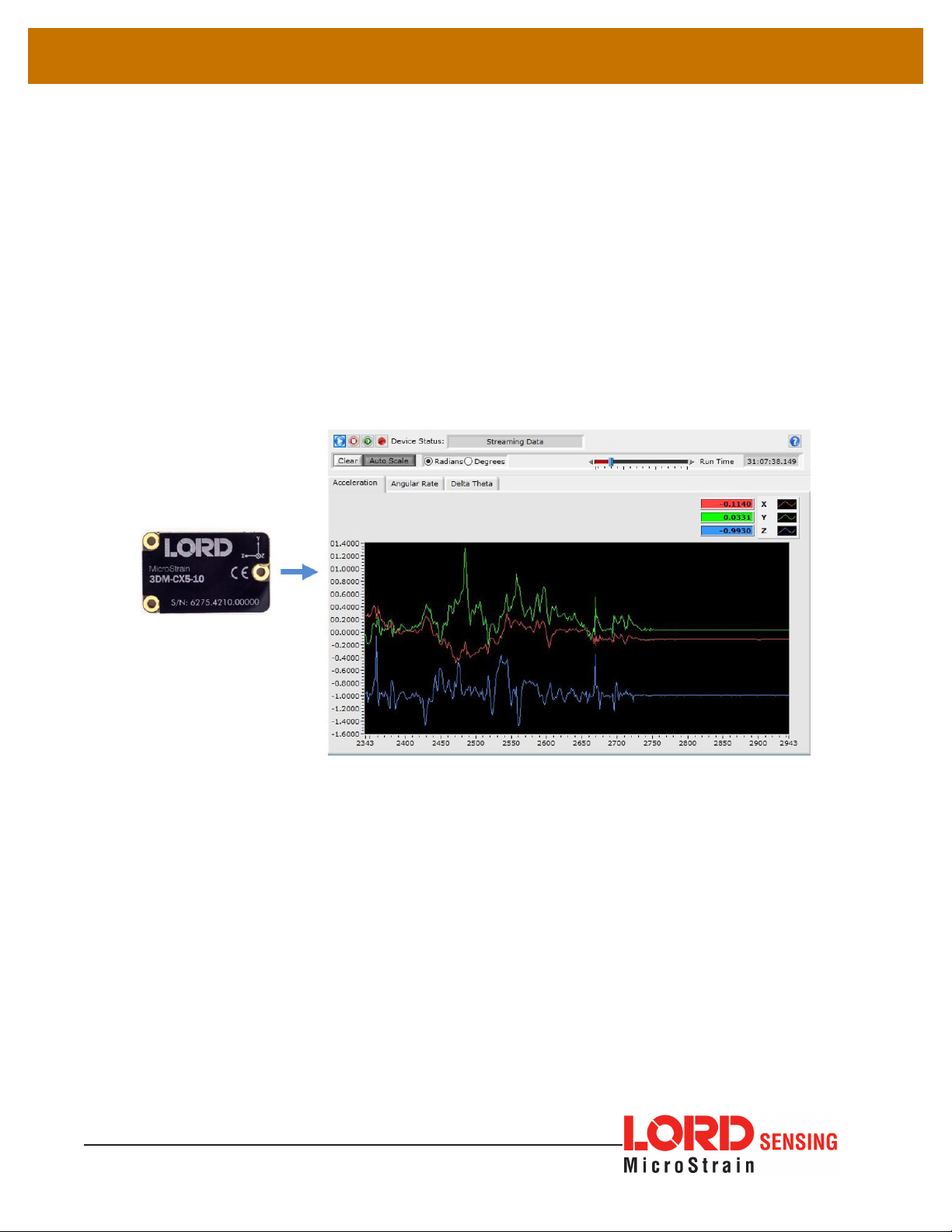
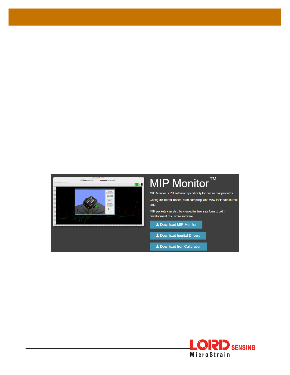
such as RS422, RS232 and USB. The LORD Sensing MIP Monitor software can be used
for device configuration, real time measurement monitoring, and data recording. The LORD
Sensing MIP Data Communications Protocol (DCP) that is used to communicate with LORD
Sensing inertial sensors is also available for users who want to develop customized software
solutions. Because of the unified set of commands across the sensor family, it is easy to
migrate code from one inertial sensor to another.
Common applications of LORD Sensing inertial sensor products include vehicle health
monitoring, platform stabilization, down- hole and drilling operations, and inertial navigation
systems such as unmanned air and ground vehicles and personal navigation systems.

2
3DM®-CX5-10 USER MANUAL
2. Sensor Overview
The 3DM-CX5-10 is a high-performance, industrial-grade, board-level Inertial Measurement
Unit (IMU) that utilizes micro inertial sensors for use in a wide range of industrial-grade
applications, such as platform stabilization and vehicle health monitoring.
The 3DM-CX5-10 combines the strengths of an integrated multi-axis gyroscope and
accelerometer, in combination with temperature readings to provide highly accurate
inertial measurements. All sensor measurements are temperature-compensated and are
mathematically aligned to an orthogonal coordinate system. The combination of sensors
and environmental compensation allows the 3DM-CX5-10 to perform well in a wide variety
of applications that require low noise, drift, gain, and offset errors. and bias estimation
outputs are available. Settings for sensor filtering, sensor noise, and sensor bias, offer many
adjustments for specific application needs.
The 3DM-CX5-10 communicates through a serial connection and is monitored by a host
computer. Sensor measurements and computed outputs can be viewed and recorded with
the LORD Sensing MIP Monitor software that is available as a free download from the LORD
Sensing website. Alternatively, users can write custom software with the LORD Sensing open
source data communication protocol. The data is time-aligned and available by either polling
or continuous stream.
Figure 1 - 3DM-CX5-10 Sensor

3
3DM®-CX5-10 USER MANUAL
2.1 Components
The 3DM-CX5-10 Inertial Sensor can be purchased by itself or as part of a Development
Kit. All software, drivers, and links to detailed documentation are included with the sensor
purchase. For a complete list of available configurations, accessories, additional system
products, and ordering information, see Parts and Configurations on page 31.
Item Description Model LORD Sensing
Part Number
A
3DM-CX5-10 Inertial Sensor IMU 8G, 300 DPS* 6275-4210
MIP Monitor Software Suite http://www.microstrain.com/software
* For additional options available see Specifications on page 1
RS232 Development Kit
B
RS232 Communication Cable
-- 6212-3010
RS232 Power Supply and Plug
Adapters
C-Series Connectivity Board
Ribbon Cable
Table 1 - 3DM-CX5-10 Components

4
3DM®-CX5-10 USER MANUAL
2.2 Interface and Indicators
The 3DM-CX5-10 sensor interface includes a communications and power input connector.
The sensor is installed using the mounting and alignment holes as needed.
The indicators on the 3DM-CX5-10 include a device status indicator and the device
information label. The table below describes the basic status indicator behavior. includes the
sensor frame diagram (axis orientation), which will be critical during device installation.
Indicator Behavior Device Status
device
status
indicator
OFF No power applied
Rapid flash Dtreaming data
Slow pulse Idle mode, awaiting
commands
Figure 2 - Sensor Indicator Behaviors

5
3DM®-CX5-10 USER MANUAL
3. Basic Setup and Operations
To acquire sensor measurements and computed outputs, the 3DM-CX5-10 uses a host
computer, an RS232 serial communications port, and applicable software. The LORD Sensing
MIP Monitor software is provided with the system and includes all functions needed for sensor
configuration and data acquisition. Users may also utilize the LORD Sensing MIP Data
Communications Protocol (DCP) to write custom software applications with expanded or
specific feature sets needed for the application. MIP Monitor includes a message building tool
that can be used to streamline this process. For more information, see System Integration on
page 23.
In this section, hardware and software setup is described, including an overview of the MIP
Monitor software menus required to configure a sensor and begin data acquisition. This is not
a complete demonstration of all system or software features and capabilities.
Figure 3 - Viewing Sensor Data with MIP Monitor

6
3DM®-CX5-10 USER MANUAL
3.1 Software Installation
NOTE: The MIP Monitor Software Suite includes hardware drivers required for 3DM-
CX5-10 sensor operation. Sensors will not be recognized without these drivers
installed.
To Install the MIP Monitor software on the host computer, complete the following steps:
1. Launch the MIP Monitor software installation menu at: https://www.microstrain.com/
software
2. Download and open the MIP Monitor.zip file.
3. Run the setup.exe file, and follow the on-screen prompts to completion.
4. Download and open the Inertial Drivers zip folder to install the hardware drivers
required for operating the sensor.
5. Run the.msi file, and follow the on-screen prompts to completion.
6. Run the setup.exe file, and follow the on-screen prompts to completion. If prompted,
reboot the computer when complete.
Figure 4 - Software Installation Menu

7
3DM®-CX5-10 USER MANUAL
3.2 System Connections
CAUTION
Power is applied to the sensor through an external power supply, such as the one provided in
the kit. Use only power supplies within the operating range of the sensor, or damage or injury
could result. Once power is applied the sensor is on and active.
To acquire sensor data the following components are needed: 3DM-CX5-10 sensor,
communication cable, power cable (as applicable for RS232 communications), connectivity
board, and a host computer with LORD Sensing MIP Monitor installed.
Figure 5 - System Connections

8
3DM®-CX5-10 USER MANUAL
3.3 Software Interface
The MIP Monitor software includes a main window with system information and menus, a
device settings window, and several data monitoring windows.
The main window provides an overview of connected devices. Devices are selected by
clicking on them. A device menu is available by right-clicking on the device name and includes
the most used items from the header row menus. The header row menu includes selections
for data sampling, recording, device settings, opening windows, selecting which open window
to view, and advanced features such as selecting the communications mode. The icon toolbar
includes buttons for Help Menu access, where all related documentation is available in Web
Resources, device refresh, and data sampling and recording.
Figure 6 - Main Window Display
3.3.1 Interactive Help Menu
MIP Monitor also includes a mouse-over feature that provides explanations of the information
and settings. This feature is enabled by selecting the question mark icon or Help button in any
window.
Figure 7 - Context Sensitive Help Menu

9
3DM®-CX5-10 USER MANUAL
3.4 Sensor Communication
Once power has been applied to the sensor, it is functional. If the hardware drivers have been
installed, communication can be established using the MIP Monitor software interface.
1. Verify the sensor device status indicator is on.
2. Open the MIP Monitor software.
3. The sensor should appear in the device list automatically when the software is
running. The list includes the device information and communication port assignment.
If the sensor is not automatically discovered, use the refresh button.
Figure 8 - Sensor Communication
NOTE: If data is not actively being exchanged between the sensor and host computer,
the status message may display Not Connected. This indicates the port status, not
the sensor availability. When commands are sent to the sensor, the software will
automatically connect to it before sending the message.

10
3DM®-CX5-10 USER MANUAL
3.5 Sensor Settings
Device settings are stored in the sensor memory. Only the configuration options available for
the sensor being used are displayed in the menus.
To enter the settings menu, either right-click on the sensor name highlighted in the main
window, and then select Device Settings, or select Settings > Device from the main menu. For
the 3DM-CX5-10 these include:
Main menu tabs: The main tabs divide the settings into functional groups for the available
measurements.
Message Format: Allows the user to select the measurement type to be displayed and
recorded and the data rate in samples/second.
Help button: Enable the context-sensitive help menu for explanations of specific settings.
Figure 9 - Device Settings Menu

11
3DM®-CX5-10 USER MANUAL
3.5.1 Saving Configurations
Sensor settings are saved temporarily by selecting the OK button in the Device Setup window
after configuration, but they are lost when the device is powered off. To save current settings,
so they are automatically restored the next time the device is powered on, select Settings >
Save Current Settings.
First adjust the sensor settings to the desired values. Next select Settings > Save Current
Settings from the main window. The settings will now remain intact when the sensor is
powered off and then on again.
To recall the last saved settings select Settings > Load Startup Settings. To revert the settings
back to the factory defaults, select Settings > Load Default Settings.
Figure 10 - Save Sensor Settings

12
3DM®-CX5-10 USER MANUAL
3.6 Data Monitoring and Recording
Throughout the MIP Monitor views the same icons are used to control data streaming
(sampling) and recording. These icons can be found in the MIP Monitor main window icon
toolbar and in each data monitoring window. The same commands are also found in the main
window Control menu.
Figure 11 - Main Window Controls
There are several data monitoring views available depending on what measurements are
desired for monitoring and recording. Each view corresponds to one of the main categories in
the Device Settings window. For example, the 3DM-CX5-10 includes Sensor Data Monitoring
for the IMU/AHRS measurements. During viewing and recording, only the outputs that are
selected in the Message Format tab are displayed and recorded.
Data streaming must be started in order for data to be recorded, however it is not necessary
to view it in a data monitoring window. Data monitoring is used primarily to confirm the system
is operating correctly or to view the outputs in near real time. If sensor setup has already been
confirmed, streaming and recording can be initiated from the main window.

13
3DM®-CX5-10 USER MANUAL
Figure 12 - Data Streaming is an example of Sensor Data Monitoring, which displays the
selected IMU/AHRS measurements. In data monitoring windows, no data will be displayed
until data streaming is started, and no data will be recorded (even if it is being viewed) until
data recording is initiated (armed). In the example below, the y- axis of the graph indicates
data points, the x- axis is the measurement units, and there is a tab for each measurement.
1. Right- click on the device in the MIP Monitor software main window, and select
Sensor Data Monitor.
2. Select the blue Start Streaming icon to start sampling.
Figure 12 - Data Streaming

14
3DM®-CX5-10 USER MANUAL
3.7 View Recorded Data
Recorded data is stored in either Binary (.bin) or Comma Separated Values (.csv) format,
depending on what was selected at the initiation of data recording. The files can be found in
the directory specified at that time or in the default directory on the host computer desktop.
CSV files can be viewed with Microsoft Excel, Quattro Pro, Open Office, or other CSV editors
and spreadsheet programs.
Data recorded in Binary format requires a translation program utilizing the LORD Sensing
MIP Data Communications Protocol (DCP) to make it user-readable.
1. To record data, select the Arm Recording icon at any time.
2. Select the type of data file to generate: Binary or CSV. The CSV file is the most
common and can be viewed and processed by data editors such as Microsoft Excel.
3. To save a settings file when creating a data file, check the box next to this option.
This settings file is the same as selecting Export Settings from the Settings menu.
NOTE: If the data is recorded in Binary format it will require a translation program that utilizes
the LORD Sensing MIP Data Communications Protocol (DCP) to make it user-
readable.
Figure 13 - Data Recording
4. To end recording press the Arm Recording button again, and select OK in the
confirmation prompt window.
5. Select the Stop Streaming icon to end sampling.
6. Use the red “X” in the upper right of the sensor monitoring window to exit monitoring
mode.

15
3DM®-CX5-10 USER MANUAL
4. Sensor Measurements
The 3DM-CX5-10 block diagram describes its primary hardware components and internal
configuration. Integrated Micro-Electro-Mechanical System (MEMS) sensors within the
3DM-CX5-10 are collectively known as the Inertial Measurement Unit (IMU) and include
tri-axial gyroscopes (gyros) and tri-axial accelerometers. This technology provides direct
measurements of acceleration, angular rate, Delta-theta (change in angular rate), and Delta-
velocity (change in velocity). Temperature sensors provide environmental information for
measurement compensation. information can be read directly but is not used internally for
attitude or navigation estimations on the 3DM-CX5-10.
Figure 14 - Block Diagram

16
3DM®-CX5-10 USER MANUAL
4.1 Direct Sensor Measurements (IMU Outputs)
The sensors in an Inertial Navigation System (INS), from which measurements for navigation
and orientation are obtained, are collectively known as the Inertial Measurement Unit (IMU).
These sensors are arranged on the three primary axes (x, y, and z) to sense angular rate
acceleration. The gyroscopes are used to adjust the current attitude estimate when an
angular rate is sensed. The accelerometers sense gravity as well as linear acceleration.
All measurements are temperature- compensated and are mathematically aligned to an
orthogonal coordinate system.
The IMU sensors can be read directly to report standalone inertial measurements or computed
measurements. Because the sensor system is digital, the analog voltage readings from the
sensors are converted into a digital equivalent value based on the volt-to-bit scale of the
internal analog-to-digital voltage converter. In the MIP Monitor software the conversion values
are not configurable, but there are user-settable options for how the measurement is made.
These settings are available at: Settings > Device > IMU (tab). With the Help window open
(accessed with the Help button), mousing over context-sensitive settings provides a detailed
explanation of the setting.
Figure 15 - IMU Settings
Table 2 - IMU Measurements lists the IMU measurements available for the 3DM-CX5-10.
Additional measurement units may be available in MIP Monitor for some outputs, however
they are converted values and do not represent the actual sensor outputs. Only actual output
units are listed.
Table of contents
Other Lord MicroStrain Measuring Instrument manuals
Popular Measuring Instrument manuals by other brands

KPS
KPS KPS-PA50 MINI instruction manual

Stihl
Stihl Laser 2-in-1 instruction manual

Extech Instruments
Extech Instruments MO53 user manual

EUTECH INSTRUMENTS
EUTECH INSTRUMENTS WATERPROOF CYBERSCAN DO 300 DISSOLVED OXYGEN... instruction manual

Sourcetronic
Sourcetronic ST2516 manual

3Egreen
3Egreen CM03-01 manual

Sensaphone
Sensaphone 2000 user manual

Endress+Hauser
Endress+Hauser Proline Promag W 400 Brief operating instructions

Endress+Hauser
Endress+Hauser Memosens CLL47E operating instructions

Sifos Technologies
Sifos Technologies PowerSync PDA-300 Reference manual

OPW
OPW 200TG Installation and maintenance instructions

RMG
RMG EC 900 operating instructions