Losma Darwin 600 Series User manual

Manuale d’istruzioni
Instructions manual
Manuel d’instructions
Handbuch
Manual d’istrucciones
Mod. 600 - 1200 - 2000 - 3000
EN
IT
FR
DE
ES

INDEX
1. GENERAL INFORMATION.........................................................................................................20
1.1. MANUAL USE..............................................................................................................................20
1.1.2. TYPOGRAPHIC INFORMATION......................................................................................................................20
1.2. WARRANTY ................................................................................................................................20
1.3. GENERAL DELIVERY NOTES.........................................................................................................21
1.4. OPTIONAL PARTS .......................................................................................................................21
1.5. PRODUCT MODIFICATIONS........................................................................................................... 21
1.6. MANUFACTURER IDENTIFICATION DATA .......................................................................................21
1.7. AIR FILTER IDENTIFICATION DATA ................................................................................................ 21
1.8. GENERAL SAFETY INFORMATION ................................................................................................. 22
1.8.1. GENERAL SAFETY PROVISIONS ...................................................................................................................22
1.8.2. POSITION OF "DANGER AND WARNING LABELS" ............................................................................................22
1.8.3. NOISE LEVEL.............................................................................................................................................22
1.9. PERSONNEL QUALIFICATION .......................................................................................................22
1.10. DIFFERENT MODELS AND USES: ................................................................................................23
1.11. NON-CONSIDERED USES ...........................................................................................................23
1.12. REQUESTS OF TECHNICAL ASSISTANCE..................................................................................... 23
2. DESCRIPTION ............................................................................................................................23
2.1. FUNCTION AND FIELD OF APPLICATION ........................................................................................23
2.2. TECHNICAL CHARACTERISTICS....................................................................................................24
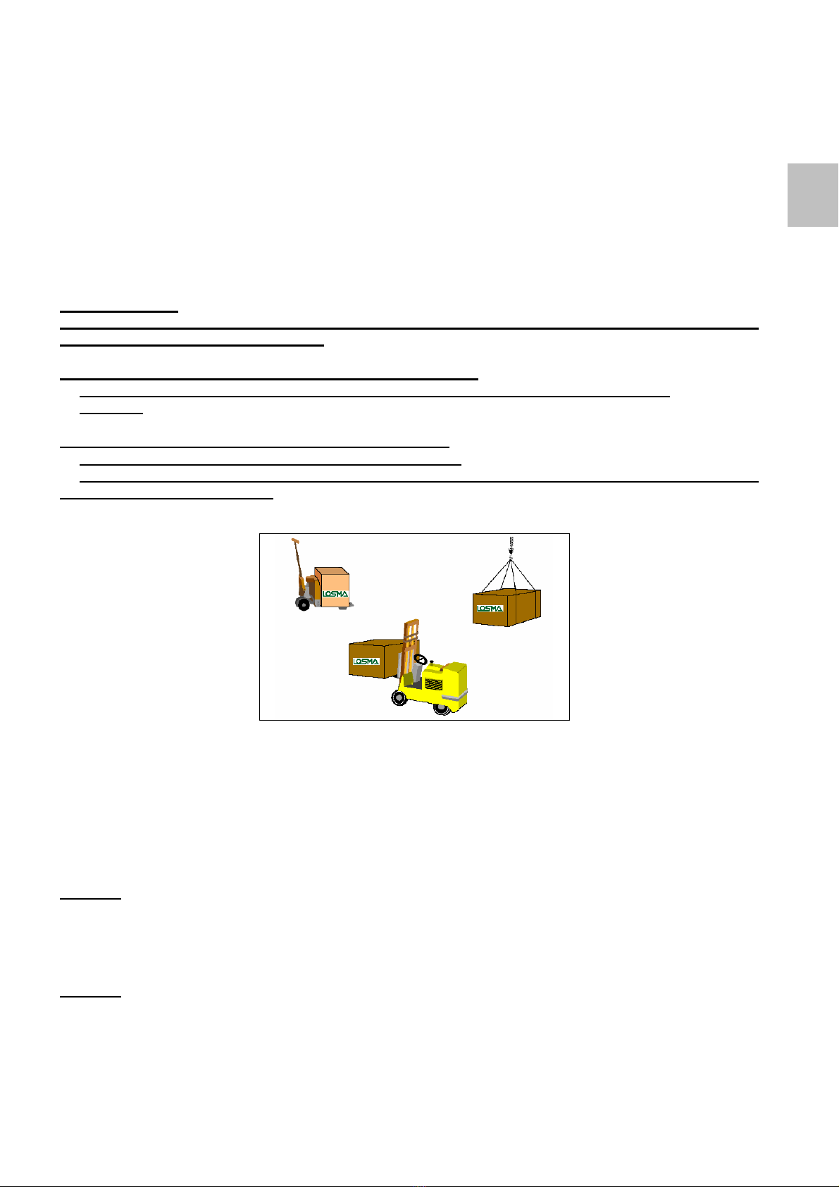
3. HANDLING AND STORAGE ......................................................................................................24
3.1. HANDLING OF PACKED UNITS ......................................................................................................24
3.2. STORAGE ...................................................................................................................................24
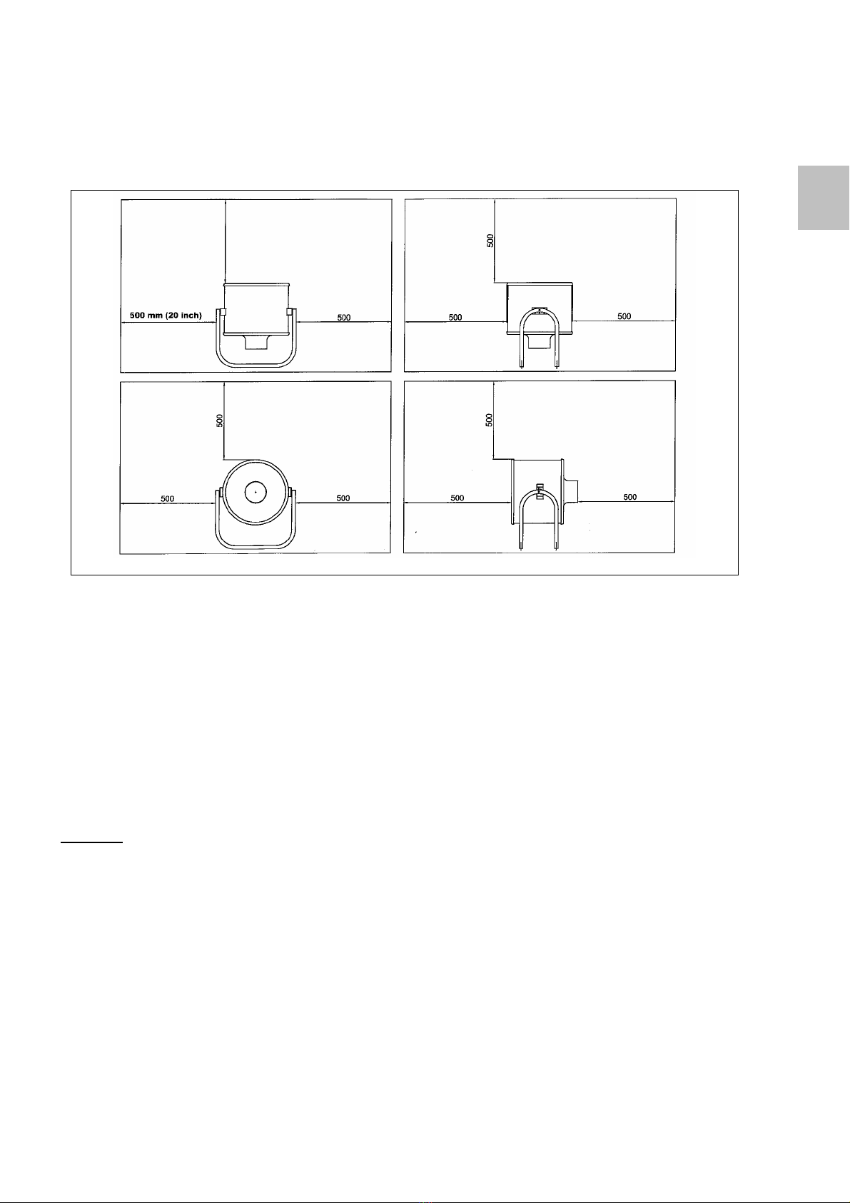
4.INSTALLATION ..........................................................................................................................24
4.1. MINIMUM SPACES FOR INSTALLATION ..........................................................................................25
4.2. CONDITIONS AND OPERATIONALLIMITS ..........................:............................................................25
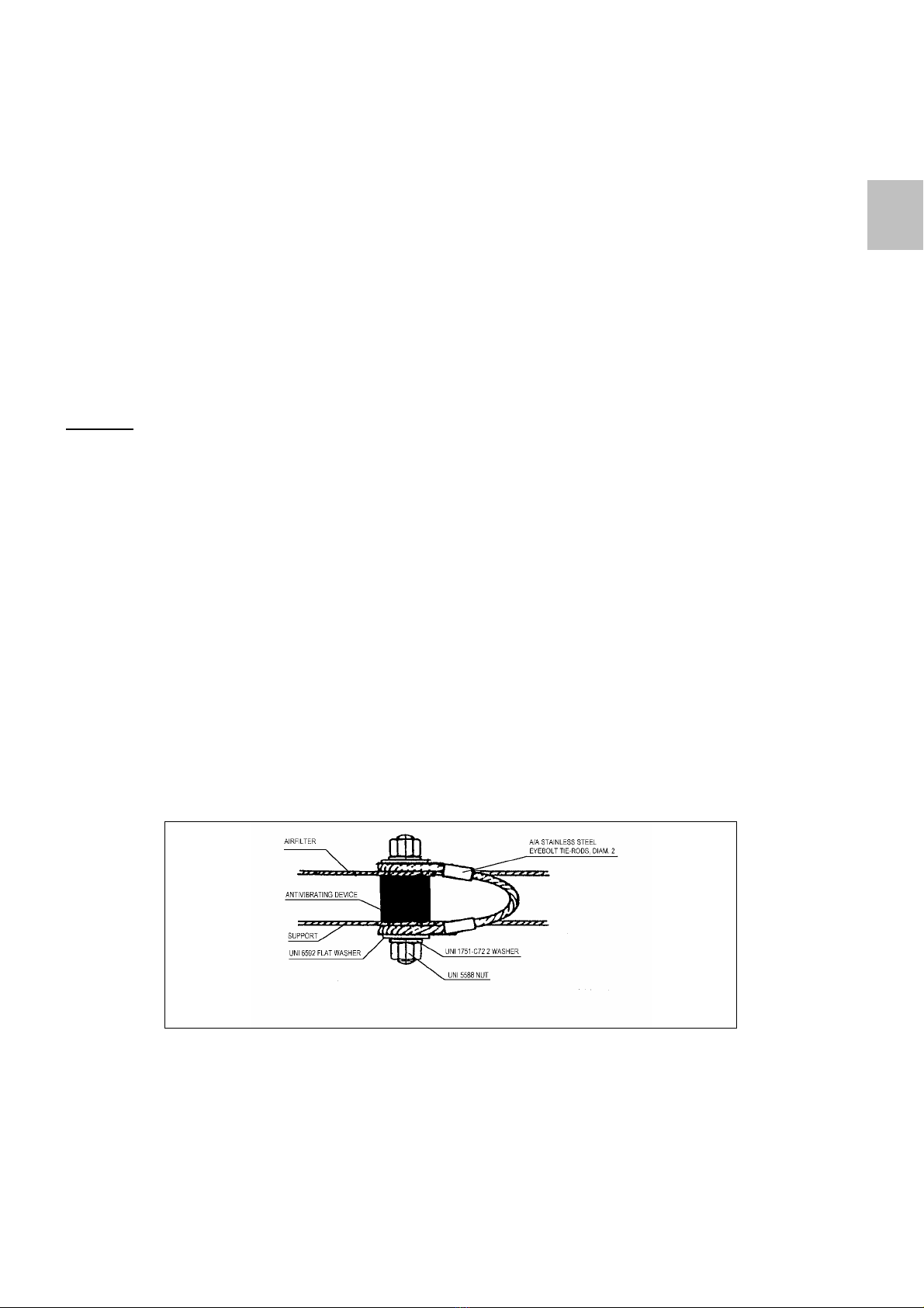
4.3. INSTALLATION ............................................................................................................................26
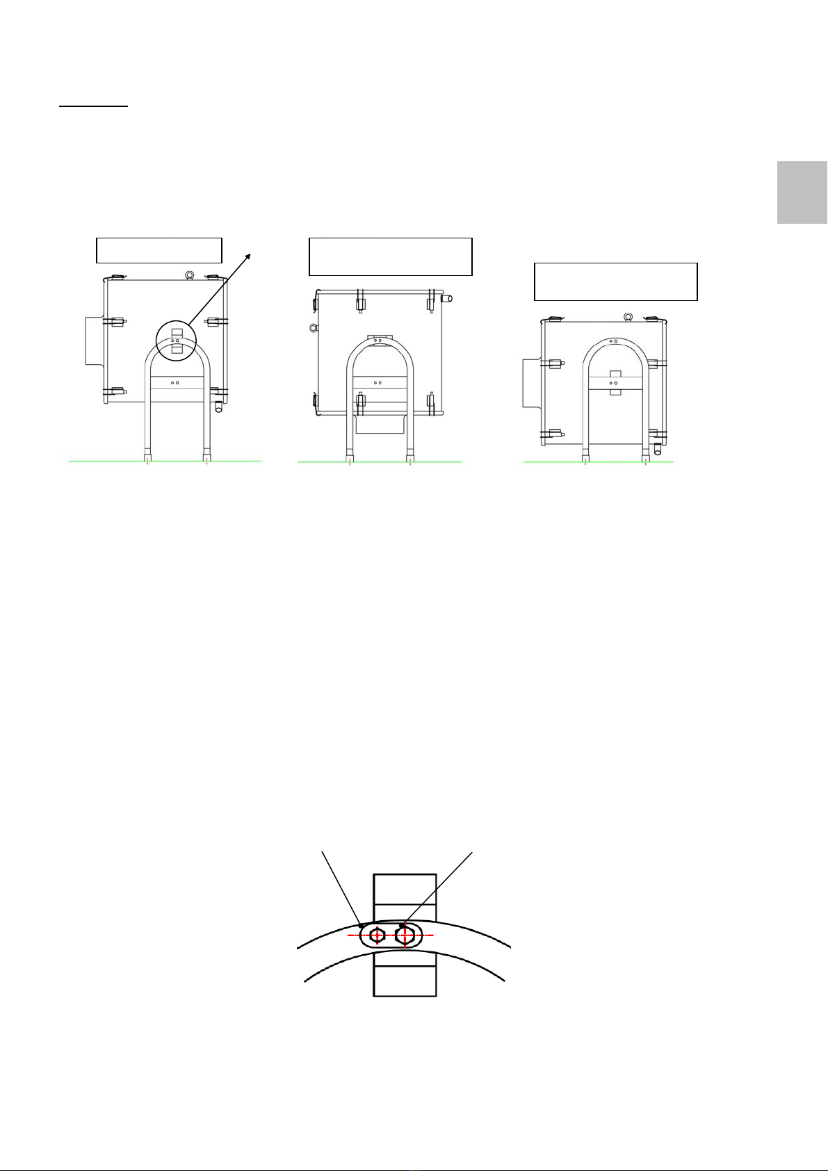
4.3.1. DETERMINATION OF THE FUNCTIONING POSITION:HORIZONTAL OR VERTICAL ...............................................27
4.4. ELECTRICAL CONNECTIONS ........................................................................................................29
4.5.INSPECTION................................................................................................................................30
5. USE .............................................................................................................................................30
5.1. STARTING UP AND STOPPING......................................................................................................30
5.1.1. EMERGENCY STOP ....................................................................................................................................30
5.2. ADVICE FOR CORRECT USE ......................................................................................................... 30
6. MAINTENANCE ..........................................................................................................................30
6.1. OPERATOR QUALIFICATION ......................................................................................................... 30
6.2. EXTERNAL CLEANING .................................................................................................................30
6.3. PROGRAMMED MAINTENANCE .....................................................................................................31
6.3.1. PROGRAMMED MAINTENANCE TABLE........................................................................................................32
6.3.2. ROTOR,SEAL AND FILTER MAINTENANCE....................................................................................................33
6.3.3. FILTER CLEANING ......................................................................................................................................34
6.3.4. INTERNAL CLEANING ..................................................................................................................................34
6.4. SPECIAL MAINTENANCE ..............................................................................................................34
6.4.1. GENERAL DISASSEMBLY AND REASSEMBLY .................................................................................................34
6.4.2. MOTOR MAINTENANCE ...............................................................................................................................35
6.5. STRUCTURAL CHECKS ................................................................................................................36
7. DISPOSAL ..................................................................................................................................36
EN

20
1. General information
1.1. Manual use
Before undertaking any equipment assembly or maintenance operation on the air filter carefully read the instructions
provided in this manual.
1.1.2. Typographic information
Note
The word "NOTE", on the left side of the page, signals important information
Warning!
The word "WARNING", on the left side of the page, indicates those procedures for which the partial or
total failure to comply may cause damages to the air filter unit or to the machine tool connected to it.
Danger!
The word "DANGER", on the left side of the page, indicates those procedures for which the total or
partial failure to comply may cause injury to the operator.
1.2. Warranty
1. General conditions
Losma S.p.A. (hereinafter known as Supplier) undertakes to deliver to the purchaser products conforming to the agreement
which are exempt from defects such as to make them unsuitable for the use to which products of the same type are
employed and guarantees the products sold for 365 days from the date of delivery with an hourly limit of use equal to 2000
hours.
The guarantee ex-Supplier’s works is limited to the replacement or repair of the products which, in the unquestionable
opinion of the Supplier, are defective.
Components not directly constructed by the Supplier will be the subject of a guarantee according to the conditions used by
his supplier to the Supplier .
It remains understood that all the components replaced shall be the property of the Supplier or his supplier.
2. Notification of non-conformity to guarantee or defective product
The notification of non-conformity or defect of the product must be communicated in writing to the Supplier with a clear
indication of its nature within 15 days of the date it was found or could have been found following a thorough examination of
the product. In addition, the purchaser, against Supplier’s request, must place at the disposal of the Supplier , the product
deemed non conforming and/or allow people assigned by the Supplier to carry out all the checks that the Supplier deems
suitable in order to ascertain the effective non conformity or defect of the product.
The lack of communication of the potential non-conformity or fault of the product in the times indicated and/or if the latter is
not made available shall cause the immediate termination of the guarantee. The purchaser also forfeits the guarantee if, the
supplier has requested the faulty piece to be returned at his expense and the purchaser omits to return such piece within a
short period of the request.
The regulations of articles 40 and 44 of the Vienna Convention shall not be applicable in any case.
3. Repairs or replacements
The Supplier shall fulfill the obligations set out in the guarantee by repairing or replacing the non-conforming or defective
parts. In order to fulfil the guarantee the Supplier can choose:
to carry out the repairs at his factory: in this case the purchaser is obliged to send at his expense, the products to
the factory indicated by the Supplier and to collect them ex-factory, after the execution of the guarantee.
to carry out or have carried out by third parties the repairs and/or replacements in the place where the products are
located. In this case the travelling costs, board and lodgings shall be at the expense of the purchaser;
to have the repair and/or replacement carried out by the purchaser supplying the relative instructions and possibly
supplying free of charge, ex the Supplier’s factory or reimbursement of the spare parts.
The guarantee for the pieces replaced or repaired terminates on the same day as the guarantee of the product.
4. Exclusions
The Supplier shall not be held liable for defects or faults pertaining to the product which are directly or indirectly attributable
to information, data, projects, materials and to any other tangible or intangible good supplied, indicated or requested by the
purchaser or by third parties acting in whatever role, in the name and on behalf of the latter.
Not covered by this guarantee are all the defects directly or indirectly attributable to incorrect, excessive or improper use of
the equipment and including all the times the equipment is used in a manner different from that described in the technical
EN

21
documentation accompanying the product. In addition excluded from the guarantee are all the parts normally subject to wear
and tear such as filters, seals, fuses etc.
The guarantee shall terminate if the product is tampered with, modified, repaired by service centres other than that of the
Supplier and by personnel not directly employed or authorised by the Supplier himself and/or in the case of the use of non-
original components or consumables (filters, seals etc).
The Supplier does not guarantee the inexistence of claims or rights based on industrial or intellectual property of third
parties, relating to the product or documentation transmitted to the purchaser.
5. Limitations of the Supplier’s responsibility (responsibility for damages)
Except in the case of malice or serious malpractice of the Supplier the possible reimbursement of any damage to the
purchaser cannot however exceed the value of the product relating to the defective part.
The guarantee as per this article includes and replaces the guarantees or responsibilities provided by the law and excludes
all other responsibilities of the Supplier not originated by the products, in particular the purchaser cannot advance other
requests for compensation for damage, price reduction or termination of the contract.
Once the guarantee has expired no claims shall be made to the supplier.
1.3. General delivery notes
The air filters are packed in carton boxes provided with handles. Upon receipt of the unit, open the box and check that:
•The air filter is not damaged.
•The goods correspond to the order specifications (see delivery note).
In the event of damage or missing parts immediately inform the forwarding agent in detail, with copy for information to
LOSMA S.P.A.
The supply consists of:
•Complete air filter unit
•Spare filter kit and seals
•Four anti-vibration joints, two safety tie-rods and connection screws.
•Instructions manual and enclosures.
•Test certificate.
•EC conformity declaration.
1.4. Optional parts
On request, special accessories are available to facilitate assembly and connection of the air filter to the machine tool. For
further details on availability of these accessories please take contact with our export sales office.
1.5. Product modifications
LOSMA S.P.A. reserves the right to make, at any moment and without notice, any change necessary to improve its products
or to meet requirements of manufacturing or commercial nature.
1.6. Manufacturer identification data
Headquarters and production plant:
LOSMA S.P.A.
Via E. Fermi,16
24035 Curno (BG)
Italia
Tel (035) 461.444
Fax ( 035) 461.671
www.losma.it
1.7. Air filter identification data
The air filter is provided with an identification plate positioned on the support frame. We recommend registering the
identification data in the following table, as they are needed for spare-parts requests.
•Series: Darwin
•Model:
•Part no.:
•Construction year:
EN

22
1.8. General safety information
In the design and construction of this unit, priority has been given to criteria and adaptations suitable to meet
the essential safety requirements, as prescribed by the European Directives 73/23/EEC and 89/392/EEC,
subsequent modifications (91/368/EEC - 93/44/EEC - 93/68/EEC) and applicable regulations. Please note that,
in accordance with the provisions of the machine directive 89/392/EEC, the air filter is to be considered as an
integral part of the machine tool. Therefore, the air filter cannot be put into operation until the machine, of
which it is an integral part (and component), is declared in conformity with the provisions of the directive
89/392/EEC and subsequent modifications. Qualified staff, according to the instructions provided in the present
manual in any way by respecting the corresponding rules and laws, must carry out installation and electrical
connection operations.
LOSMA S.P.A. recommend following carefully the instructions, procedures and suggestions contained in this
manual and in the current "accident prevention regulations".
1.8.1. General safety provisions
Danger!
•Before undertaking any cleaning or maintenance operation, disconnect the machine from its power
supply, as follows:
- Cut off the power by turning the main switch on "OFF". To prevent any sudden starting up, it is
advisable to fasten the switch with a padlock.
- Turn the main switch (positioned on the machine switch-board) to "OFF" and fasten it with a padlock.
- Disconnect the control device from the plug and socket of the air filter.
- Wait at least 3 minutes in order to allow the air filter rotor to come to a complete stop.
•Check that the external PE protective conductor of the air filter is correctly earthed.
•Wear suitable accident prevention clothing during the assembly and maintenance operations.
•To reach the unit for assembly or maintenance operations, use only ladders and/or gangways
conforming to current accident prevention regulations.
Note
LOSMA S.P.A. does not accept any responsibility for any direct or indirect damage to persons or things
resulting from incorrect or different use of the air filter than those prescribed in the present manual.
1.8.2. Position of "danger and warning labels"
Some of the adhesive labels applied to the machine complete and repeat the instructions of this manual. Should the wear
and tear of time make them illegible, replace them with new ones.
See attached enclosure “Position of the warning labels”.
1.8.3. Noise level
Noise level data, for each model, is indicated in enclosure "Technical Specifications".
Note
The noise level data indicated in the Technical Specifications has been recorded (as per ISO 3746) with free inlet. These
data may change according to the installation conditions of the air filter (assembly on enclosed machine tools or on open
cabin, etc.).
1.9. Personnel qualification
Qualified personnel must undertake installation, maintenance and use of the air filter unit. Exclusively qualified electricians
should carry out electrical connection of the unit.
EN

23
1.10. Different models and uses:
•Darwin mod. 600 M – 1200 M- 2000 M - 3000 M
Filtration and purification of air containing mist from neat or soluble oil also in presence of small quantities of solid particles.
•Darwin mod. 600 D – 1200 D- 2000 D - 3000 D
Filtration and purification of air containing mist and vapours from neat or soluble oil also in presence of small quantities of
solid particles.
•Darwin mod. 600 T – 1200 T- 2000 T - 3000 T
Filtration and purification of air containing mist from neat or soluble oil also in presence of a considerable amount of solid
particles.
1.11. Non-considered uses
•Suction of substances different from neat or soluble oil mist.
•Suction of corrosive vapours.
•Suction of explosive substances in an explosive atmosphere.
Note
LOSMA S.P.A. declines any responsibility for damage to persons or things caused by "Non-considered uses" of the air
filter unit.
1.12. Requests of technical assistance
For technical assistance, please contact:
LOSMA S.P.A.
Via E. Fermi,16
24035 Curno (BG)
Italia
Tel. +39 035 461444
Fax. +39 035 461671
LOSMA GmbH
Albert Einstein Strasse, 2
D-70806 KORNWESTHEIM-
DEUTSCHLAND
Tel.+ 49 7154-8160480
Fax + 49 7154-8160485
LOSMA INC. –
U.S.A. Branch
231 West Parkway
Pompton Plains NJ 07444 - U.S.A.
tel. +1 973 2480070
fax +1 973 2483280
2. Description
2.1. Function and field of application
•The air filter DARWIN D (double centrifuge) is suitable for all machine tools for metal production (other than
grinders and sharpeners). It specifically eliminates neat or soluble oil mist and vapours, also in the presence of small
amounts of solid particles.
•The air filter DARWIN M (monocentrifuge) is suitable for all machine tools for metal production (other than
grinders and sharpeners) It specifically eliminates neat or soluble oil mist, also in presence of small amounts of solid
particles.
•The air filter DARWIN T (turbine) is suitable for grinders and sharpeners. It eliminates soluble oil mist, also in
presence of relevant amounts of solid, metallic and abrasive particles.
Note
•The mist of soluble or neat oil (air + liquid pollutant with particle dimensions between 0.8 and 10
µ
m*) are
generated by the action (purely mechanical) of rotating parts such as tools, pieces being machined, etc.
•The vapours from neat or soluble oil (air + liquid pollutant with particle dimensions between 0.5 and 0.8
µ
m*)
are generated by the thermal actions (friction heat between piece and tools, electrical resistance heat as that
generated during hardening treatments) and by pressure (forced atomisation of coolants, high pressure forced
lubrication)
*
(The declared values are purely indicative)
Warning! Danger!
The air filters are not suitable for dry dust. They do not absorb this kind of pollutant which, after suction is re-
circulated in the air. In case of production generating dry dust, the air filter is not effective and must be
disconnected.
EN

24
2.2. Technical characteristics
See: “Enclosure Technical Specifications".
3. Handling and storage
3.1. Handling of packed units
Every unit is packed in highly resistant carton boxes provided with handles. When the shipment consists of more boxes, they
are placed on EUR pallets, firmly tied up with hoops and fully wrapped in polyethylene film.
Warning! Danger!
Forklift operators, crane-operators and other adequately trained personnel must undertake the handling
and transportation of the air filter units.
A single carton box containing the air filter can be handled by:
•Two people, manually, using the two handles on the carton boxes (except Darwin 3000).
•A fork-lift
The EUR pallet with several boxes is to be transported by:
•A forklift of adequate capacity for the load to be handled.
•Cranes, bridge cranes or other lifting means of adequate capacity and with characteristics suited to
the weight and form of the load.
Illustration 1: Lifting and transportation
3.2. Storage
The air filter unit must be stored in a dry place protected from the atmospheric elements and dust. The following
environmental features must also be respected:
•Permitted temperature: from 0°C to 40°C +/- 5°C.
•Permitted relative humidity: from 30% to 80% +/- 5%.
Warning!
Do not overturn the boxes (arrow upwards) and do not stock more than 4 boxes on top of each other.
4 Installation
Warning!
Exclusively specialized personnel must install the air filter. Complying with the corresponding laws and
regulations.
EN

25
4.1. Minimum spaces for installation
Before proceeding with the air filter installation, make sure that there is enough space (0.5 m) as indicated in
drawing 2, so as to permit the use and maintenance of the air filter in safe conditions.
Drawing 2: Minimum space for installation
4.2. Conditions and operational limits
To obtain maximum efficiency from the air filters of the Darwin range the physical characteristics of the air to be purified
should preferably respond to the following characteristics:
•Temperature: between 5°C and 40°C.
•Relative humidity: from 30% to 98%.
While the ideal characteristics of the environment where the air filters are installed should be:
•Temperature: from 5°C to 40°C
•Relative humidity: from 30% to 85%
•Maximum installation height: 1000 m a.s.l.
Warning!
LOSMA S.P.A. declines any responsibility for damages to the units installed in working conditions different than
those specified above.
EN

26
4.3. Installation
To mount the air filter, as well as the material supplied in the assembly kit, the following components are also necessary:
•Flexible suction hose TFM of adequate length + 2 hose clamps
•Flexible suction hose diam. 25 mm, TFD of adequate length + 1 hose clamp
•In case the machine is enclosed, PRT pipe connection plate, nuts and bolts.
•Find a suitable position for the installation of the air filter (on the machine tool or immediate close to it) and decide the
position of the air filter (vertical or horizontal) according to the available space or the shape of the machine cabin.
•Drill the necessary holes to position the air filter on the machine cabin, as illustrated in the drilling schemes (enclosure
“Drilling schemes”).
•If the PRT pipe connection plate is necessary, drill the 4 holes, diam. 5, on the machine cabin, as illustrated in enclosure
no.3 “Drilling schemes”.
Warning!
•In order to avoid dangerous filtering of solid dust and coolant liquids, it is advisable to keep the suction hose
away from areas with a considerable presence of solid dust and sprays of coolant liquids.
•To avoid pressure drop, it is advisable to use a suction pipe with a maximum length of 2 metres. Furthermore, to
prevent liquid stagnation inside the flexible pipes, avoid depressions when positioning it.
•Insert an eyebolt of one of the supplied safety tie-rods, on the threaded pins of the anti-vibration joints.
•Assemble the 4 anti-vibration joints on the previously drilled support surface, positioning the 2 joints - complete with
safety tie-rods - in a diagonal position, as indicated in drawing 3.
- If you have drilled clearance holes, fix the anti-vibration joints to the support surface by means of the washer and nuts
supplied.
- If you have drilled threaded holes, screw the anti-vibration joints directly on the support surface.
•If foreseen, fix the PRT pipe connection plate to the machine tool cabin
•Lift the air filter by means of the special eyebolt and position it on the anti-vibration joints.
•Insert the other end of the 2 safety tie-rods on the threaded pin of the anti-vibration joints.
•Mount the washers and nuts on the 4 threaded pins of the anti-vibrating joints.
•Tighten firmly.
Drawing 3: Safety tie-rods assembly scheme
EN

27
Important!
The packaged equipment is always shipped with the screws loosened. This ensures that the Ø6mm screw,
which restricts the rotation, does not get damaged during transportation or when the product is being extracted
from the packaging.
Once the product has been extracted from the packaging, it is possible to choose the position, as shown in the
illustration.
Fig.A Fig.B Fig.C
The three illustrations show the possible positions taken on by the product: horizontal or vertical.
In fig. C, provided for the assembly of the Darwin with pre-filters and post-filters, the body of the aspirator must
be released from its support (cradle) and moved on holes prepared in the underlying transverse beam (except
for the Darwin 600, in which there is only one transverse beam).
In this position, the aspirator can only be used in a horizontal position.
4.3.1. Determination of the functioning position: Horizontal or Vertical
In order to rotate the equipment, having the N°2 Ø8 screws as a fulcrum, “screw 1” must be slightly loosened to
enable movement, after which “screw 2” must be unscrewed, making it exit from the seat made in the body of
the aspirator.
Once the required rotation has been carried out (either Vertical or Horizontal), re-screw “screw 2”, making it
return back to the appropriate seat and tighten completely “screw 1”.
Enlargement A
Screw2 Screw1
A
DARWIN Horizontal DARWIN Vertical
DARWIN + Prefilters/Postfilters
DARWIN Horizontal
DARWIN + Prefilters/Postfilters
EN

28
Installation in vertical position (drawing 4)
•Insert the pipe TFM on the connection plate PRT and secure it using a hose clamp. In alternative, the pipe can be
inserted directly into the hole made on the machine tool cabin.
•Insert the other end of the pipe into the suction mouth of the DARWIN and secure it using a hose clamp.
•Insert the oil drainage pipe TFD in the oil discharge pipe of the DARWIN and secure it using a hose clamp.
•Insert the other end of the drainage pipe into the hole made on the machine tool cabin. In alternative, in case you
prefer not to re-use the re-condensed oil, insert the other end of the drainage pipe into an open container to be
regularly emptied.
VERTICAL INSTALLATION
Drawing 4: Vertical installation
Installation in horizontal position (drawing 9)
•Insert the pipe TFM on the connection plate PRT and secure it using a hose clamp. In alternative, the pipe can be
inserted directly into the hole made on the machine tool cabin.
•Insert the other end of the pipe into the suction mouth of the DARWIN and secure it using a hose clamp.
•Insert the oil drainage pipe TFD in the oil discharge pipe of the DARWIN and secure it using a hose clamp.
Insert the other end of the drainage pipe into the hole made on the machine tool cabin. In alternative, in case you prefer not
to re-use the re-condensed oil, insert the other end of the drainage pipe into an open container to be regularly emptied.
Note!
To ensure optimum functioning of the DARWIN in both mounting positions:
•Do not obstruct the inlet
•Do not obstruct the exit of the drainage hose.
HORIZONTAL INSTALLATION
Drawing 5: Horizontal installation
EN

29
4.4. Electrical connections
It is advisable to keep the air filter in operation during the entire work shift, in order to avoid frequent starting and
stopping. In this way the air filter ensures the best performance and is not subject to unnecessary and
detrimental thermal and mechanical stress.
Warning! Danger!
Before making the electrical connection of the air filter cut off the power supply (main switch). Exclusively qualified
electricians must carry out all operations.
A power supply automatic cut off must be used as the protection system from indirect contact (refer to the norm EN
60204-1 and 1998-04; For this reason the oilmist filter must be equipped with an equipotent protection circuit that
must include a protection switch to avoid problems in case of power supply failure as. Refer to the requirements
indicated in 413.1 of the publication IEC 60364-4-41
The DARWIN air filter in its STANDARD configuration is supplied with power cable and multi-polar plug and socket. The last
one simplifies the disassembling operations of the rear filter during regular maintenance operations.
As accessory a Stop/running switch is available on request.
It is advisable to protect the electric motor of the air filter by using a magneto thermal switch.
Note!
For Darwin 3000 with 60 Hz motor, the protection is:
a) a thermal switch for 3 ÷ 12 A with cycle time 20 seconds
b) a magnetic switch for 8 A running current.
•Check that the connection voltage indicated on the test sheet on the unit corresponds to that of the power supply
network.
•Read the motor plate information to select the correct connection materials (cable section, fuses, magneto thermal
switch, etc.)
•Make the electrical connection from the electric switchboard of the machine tool to the DARWIN power cables (see
drawing 6) inserting the multi-polar socket/plug. This will speed up and facilitate future maintenance operations.
•Assemble the chosen motor protection device inside the machine tool switch-board (magneto thermal switch for starting
the motors).
•Electrical connections must be carried out as illustrated in drawing 6 and, in any case, in compliance with applicable
norms in order to carry out a professional installation.
•Start up the air filter, following the applicable safety regulations.
•Check through the suction mouth that the direction of rotation of the air filter rotor corresponds to that indicated by the
arrow-label (the rotor must rotate in a clockwise direction).
•Should the direction of rotation be contrary to that indicated in the arrow, invert the connection between the two phases.
•Check that the motor-protector switch calibration complies with the power absorption characteristics of the motor
indicated on the motor plate.
Drawing 6: Electrical connection
EN

30
4.5 Inspection
Each air filter is carefully inspected at the factory. The inspection certificate is delivered together with the
present manual.
5. Use
Danger!
Do not start the air filter if the synthetic rear filter is missing.
5.1. Starting up and stopping
On request a running/stop switch is available to be mounted on the machine tool control panel. This switch may be used to
exclude the air filter.
However, it is advisable to start and stop the air filter only at the beginning and ending of each work shift.
5.1.1. Emergency stop
For the emergency stop procedures consult the instructions’ manual of the machine tool on which the air filter is mounted.
5.2. Advice for correct use
It is advisable to avoid, as far as possible, repeated starts and stops of the Darwin, as it may result in:
•Short motor life
•Anomalous stress on the rotor (centrifugal or turbine).
Introduction into the working atmosphere of the pollutant contained in the air, which is sucked but not purified.
Note
It is suggested to stop the Darwin only during the halts between work-shifts, with the machine tool at a standstill.
6. Maintenance
Warning! Danger!
•Respect carefully the programmed maintenance timetable illustrated in the present manual.
•Only use ladders and/or gangways that comply with the current accident prevention regulations to
reach the air filter units on which maintenance is to be done
•Use only original spare parts.
Danger!
Before beginning the maintenance procedure:
•Position the general switch of the machine tool to "OFF" and lock it.
•Wait at least 3 minutes in order to allow the rotor to come to a complete stop.
•Disconnect the control device from the plug and socket of the air filter
•Place on the machine tool the apposite sign "Maintenance in progress".
•Wear goggles and protective clothing (gloves, safety shoes, etc.).
6.1. Operator qualification
Qualified personnel, familiar with the procedures and precautions to be adopted, must undertake the programmed
maintenance operations.
6.2. External cleaning
•Position the general switch of the machine tool to "OFF" and lock it.
Every 1000 hours of operation, and more often if the working conditions require it, clean the exterior and the suction mouth of
the Darwin
EN

31
6.3. Programmed maintenance
In order to ensure the maximum efficiency of the air filter it is necessary to undertake a preventive programmed maintenance
at regular intervals.
The programmed and preventive maintenance operations consist in the periodic cleaning or substitution of filters, seals, etc.
Note
Consult enclosure "Spare parts list" for the exact location of the filters, seals, etc.
EN

32
6.3.1. Programmed maintenance table
DARWIN
500 h 1000 h 1500 h 2000 h
DARWIN T
FPS / FPSE Clean / replace Replace Clean / replace Replace
GTI Replace
GSM Replace
TURBINE Clean Clean Clean Clean
DARWIN M
FCS / FCSE Replace Replace
FPS / FPSI / FPSE Replace Replace
GTI Replace
GSM Replace
CENTRIFUGE Clean Clean
DARWIN D
FCSE / FCS Replace Replace
FCSI Replace Replace
FPS / FPSI/FPSE Replace Replace
GTI Replace
GSM Replace
CENTRIFUGE Clean Clean
Note
FCS - FCSI - FCSE - FPS - FPSI - FPSE filters can be cleaned rather than replaced at the above-mentioned intervals,
provided that their structure is fully integral.
In case of installation of the machine in smaller areas, maintenance is required more often.
K E Y
FCS Synthetic centrifugal filt
FCSI Internal synthetic centrifugal filter
FCSE External synthetic centrifugal filter
FPS Rear synthetic filter
FPSI Rear internal synthetic filter
FPSE Rear external synthetic filter
GTI Covering tubular seal
GSM Motor support seal
All filters are available in two different materials:
•Standard, black, for normal functioning conditions.
•Special, light blue, for particularly aggressive liquids and emulsions.
EN

33
6.3.2. Rotor, seal and filter maintenance
Warning!
Do not forget any objects or tools inside the air filter.
DARWIN M
•Release and remove the rear lid.
•Extract the FPS filter (for D 3000: FPSE, the net and FPSI) and the net from the rear lid.
•Remove all deposits (metal, grease, etc.) from the drainage ring of the rear lid and from the air filter
shell (see 6.3.4).
•Replace seals GSM and GTI if necessary
•Clean or replace the FPS (for D 3000: FPSE and FPSI) filter (see 6.3.3).
•Insert the FPS (for D 3000: insert FPSI, the net and FPSE) filter on the net of the rear lid.
•Reassemble and secure the rear lid.
•Remove the two safety pins mounted on hooks of the front lid.
•Release and remove the front lid.
•Extract filter FCSE (FCS for D 600) from the inside of the centrifuge.
•Clean or replace the FCSE (FCS for D 600) filter (see 6.3.3).
•Remove all deposits from the surface of the centrifuge (metallic dust, grease, etc. see 6.3.4.)
•Reposition filter FCSE (FCS for D 600) inside the centrifuge
•Replace the GTI seal if necessary
•Reassemble and secure the front lid inserting the two safety pins into the hooks.
DARWIN D
•Release and remove the rear lid.
•Extract the FPS filter (for D 3000: FPSE, the net and FPSI) and the net from the rear lid.
•Remove all deposits (metal, grease, etc.) from the drainage ring of the rear lid and from the air filter
shell (see 6.3.4).
•Replace seals GSM and GTI if necessary
•Clean or replace the FPS (for D 3000: FPSE and FPSI) filter (see 6.3.3).
•Insert the FPS (for D 3000: insert FPSI the net and FPSE) filter on the net of the rear lid.
•Reassemble and secure the rear lid.
•Remove the two safety pins mounted on hooks of the front lid.
•Release and remove the front lid.
•Extract filter FCSE (FCS for D 600) and FCSI from the inside of the centrifuge.
•Clean or replace the FCSE (FCS for D 600) filter (see 6.3.3).
•Remove all deposits from the surface of the centrifuge (metallic dust, grease, etc. see 6.3.4.)
•Reposition filter FCSE (FCS for D 600) and FCSI inside the centrifuge
•Replace the GTI seal if necessary
•Reassemble and secure the front lid inserting the two safety pins into the hooks.
DARWIN T
•Release and remove the rear lid.
•Extract the FPS filter (for D 3000: FPSE, the net and FPSI) and the netfrom the rear lid.
•Remove all deposits (metal, grease, etc.) from the drainage ring of the rear lid and from the air filter
shell (see 6.3.4).
•Replace seals GSM and GTI if necessary
•Clean or replace the FPS (for D 3000: FPSE and FPSI) filter (see 6.3.3).
•Insert the FPS (for D 3000: insert FPSI, the net and FPSE) filter on the net of the rear lid.
•Reassemble and secure the rear lid.
•Remove the two safety pins mounted on hooks of the front lid.
•Release and remove the front lid.
•Remove all deposits from the surface of the centrifuge (metallic dust, grease, etc. see 6.3.4.)
•Replace the GTI seal if necessary
•Reassemble and secure the front lid inserting the two safety pins into the hooks.
EN

34
6.3.3. Filter cleaning
Note
The used filters and the liquids used for washing are special waste. Take this waste to authorised collection and disposal
centres.
It is advisable to regularly replace the synthetic filters as indicated in the Programmed Maintenance Table (item 6.3.1). If the
filters structure is fully integral, it is possible to regenerate them (instead of replacing them) by putting them into a solution of
industrial detergent and water for about 12 hours. Before re-assembling the filters, dry them with a jet of compressed air or
leave them to dry naturally.
Danger!
The used filters and the seals are special waste. While waiting for disposal, they must be kept in hermetically
closed containers, which must be located far from the working areas.
6.3.4. Internal cleaning
Careful and regular cleaning of all the internal parts (shell, drainage pipe, drainage ring, etc.) ensures high performance and
long life of the air filter.
It is of fundamental importance to periodically check the inside of the centrifuge or the blades of the turbine to
eliminate eventual deposits of metal particles, sludge or other material which could cause loss of balance of the
centrifuge or of the turbine.
Warning
The functioning of the air filter with unbalanced turbine or centrifuge (even if for a short time) could seriously
damage the air filter components.
For the internal cleaning of the air filter and the rotors (either turbine or centrifuge) use a clean brush saturated in a mild
industrial detergent solution. Alternatively standard liquid soaps can be used.
Should the dirt be very resistant, it is advisable to remove the rotor (for rotor dismantling see 6.4) and use the following
alternative cleaning solutions:
-A jet of steam at a temperature of over 100°C.
-An industrial detergent solution in water, soaking the rotor for at least 12 hours.
Allow the centrifugal device to dry in the open air or dry with a jet of compressed air.
6.4. Special maintenance
Danger!
The special maintenance operations are to be undertaken by qualified technicians only. Skilled electricians should
carry out work on the electrical parts.
Before beginning the maintenance procedure:
•Position the general switch of the machine tool to "OFF" and lock it.
•Wait at least 3 minutes in order to allow the rotor to come to a complete stop.
•Disconnect the control device from the plug and socket of the air filter.
•Place on the machine tool the apposite sign "Maintenance in progress".
•Wear goggles and protective clothing (gloves, safety shoes, etc.).
6.4.1. General disassembly and reassembly
Warning! Danger!
During the re-assembly and before starting up the air filter again make sure that all the components are correctly
secured and mounted.
In particular, check:
•The correct tightening of the screws connecting the motor to the relative support.
•The correct tightening of the screw connecting the rotor to the motor shaft.
EN

35
•The correct assembly of filters and seals.
•The correct assembly of electrical connections.
•That there are no objects or tools inside the air filter.
•Check through the suction mouth that the direction of rotation of the air filter rotor corresponds to that
indicated by the arrow-label (the rotor must rotate in a clockwise direction).
•Reassemble and secure the front lid inserting the two safety pins into the hooks.
•Disconnect the air filter from the machine tool. To remove and lift it up use the apposite eyebolt. Place the air filter
on a workbench.
•Remove the two safety pins mounted on the hooks of the front lid.
•Release and remove the front lid.
•Release and remove the rear lid.
•Unscrew the blocking screws of the rotor.
•Using the special extractor remove the rotor from the motor shaft.
•Loosen the 4 screws, which fix the motor to the support and remove the motor.
•Unscrew the 4 nuts and the eyebolt and remove the 5 screws securing the support to the air filter shell.
•Extract the support from the shell.
To remount the air filter undertake the dismantling operations in reverse order using new safety pins, seals, washer and self-
blocking nuts.
It is also advisable to block the threads of the bolts connecting the motor support to the shell using thread-blocking
substance "Arexons sistem forte 52A70" or an equivalent product.
6.4.2. Motor maintenance
At regular intervals and, in any case, during normal maintenance of other components of the air filter, it is advisable to
regularly check that the motor shaft rotates freely and does not produce anomalous sounds.
Anomalous noises coming from the electric motor are usually an indication that the ball bearings are worn. In this case
replace them following the instructions provided below.
•
•On reassembly of the bearings and the sealing ring, avoid using inadequate tools which may damage these
components.
•On reassembling the motor install all components in their original and correct position.
•At the end of reassembly check that the shaft rotates freely and that the new bearings installed do not make any
noise.
Note
The dismantling operations indicated may vary according to the type of electric motor mounted on the air filter. The
instructions provided below is only a general indication of the recommended dismantling order of the electric motor
components.
•Dismantle the electric motor from the air filter, see paragraph 6.4.1
•Remove the tab from the electric motor shaft.
•Remove the fixture screws of the fan-cover and the cooling fan
•Loosen the 4 or 8 closure screws of the electric motor cover.
•If the motor has a rear or front bearing, unscrew the two blocking screws.
•With the aid of a plastic mallet, remove the front and rear covering. Pay particular attention to the positioning of the
pre-load washers mounted in the coverings.
•Remove the electric motor shaft.
•Dismantle the bearings using a special extractor.
•Dismantle the oil-protection bearings using a special extractor
For reassembly undertake the operations as indicated above in reverse order replacing all worn parts.
EN

36
6.5. Structural checks
•Each year:
Check that the nuts of the anti-vibration joints are firmly tightened.
•Every 2 years:
Check the condition of the safety tie rods.
Check the good condition of the Darwin shell.
•Every 4 years:
Replace the anti-vibration joints.
7. Disposal
Danger!
Solely adequately trained and equipped personnel must carry out the machine disconnection and disposal
operations.
The used filters, the internal parts in rubber and all components with oil residuals are special waste to be disposed through
authorized organizations.
To allow for the reutilization of the raw materials it is also advisable to separate:
•The metal parts.
•The electric motor.
•The rubber parts.
•The synthetic material parts.
Note
LOSMA S.P.A. does not assume any responsibility for damage to persons or things resulting from reutilization of individual
parts of the machine for operations or in assembly condition others than the original ones for which the machine was
designed.
EN

Allegato IV Parti di ricambio Attachment IV Spare Parts Annexe IV Pièces de réchange
Anlage IV Ersatzteile Anexo IV Piezas de repuesto
Darwin 600-1200-2000-3000
RIF. DESCRIZIONE DESCRIPTION DESCRIPTION BESCHREIBUNG DESCRIPCIÓN
8 GUARNIZIONE COPERCHIO
ANTERIORE
FRONT COVER GASKET JOINT COUVERCLE AVANT DICHTUNG DECKEL VORNE JUNTA TAPA ANTERIOR
12 GUARNIZIONE SUPPORTO
MOTORE
MOTOR SUPPORT GASKET JOINT SUPPORT MOTEUR DICHTUNG MOTORHALTERUNG JUNTA SOPORTE MOTOR
10 GUARNIZIONE COPERCHIO
POSTERIORE
BACK COVER GASKET JOINT COUVERCLE ARRIERE DICHTUNG DECKEL HINTEN JUNTA TAPA POSTERIOR
KIT COPIGLIE GANCI SAFETY PINS KIT 2 GOUPILLES POUR
CROCHET
SICHERUNGSSPLINTE KIT DE PASADORES
10 +12+ 8 KIT GUARNIZIONI SEALS KIT KIT JOINTS DICTHUNGSSATZ KIT JUNTAS
7 PRESA-SPINA PLUG & SOCKET PRISE ET CONTREPRISE STECKER/GEGENSTECKER ENCHUFES
15 KIT ANTIVIBRANTI ANTIVIBRATION KIT KIT ANTIVIBRATIONS SATZ VIBRATIONSDÄMPFER KIT ANTIVIBRANTE
14 SUPPORTO ASPIRATORE UNIT BRACKET SUPPORT EPURATEUR GERÄTEHALTERUNG SOPORTE ASPIRADOR
1 + 8 COPERCHIO ANTERIORE FRONT LID COUVERCLE AVANT DECKEL VORNE MIT DICHTUNG TAPA ANTERIOR
2 TURBINA TURBINE TURBINE TURBINE TURBINA
2a MONOCENTRIFUGA MONOCENTRIFUGE MONOCENTRIFUGE MONOZENTRIFUGE CENTRIFUGA
2b DOPPIACENTRIFUGA DOUBLE CENTRIFUGE DOUBLE CENTRIFUGE DOPPELZENTRIFUGE DOBLE CENTRIFUGA
8 + 9 + 10 KIT INVOLUCRO SHELL KIT KIT CARTER GEHAEUSE MIT DICHTUNGEN KIT CARCASA
5 KIT SUPPORTO MOTORE MOTOR SUPPORT KIT KIT SUPPORT MOTEUR BEFESTIGUNGSSATZ MOTOR KIT SOPORTE MOTOR
6 MOTORE MOTOR MOTEUR MOTOR MOTOR
11+16+17+
19
KIT FILTRI (Azzurri) FILTERS KIT (Blue) KIT FILTRES (Bleu) FILTERSATZ KOMPLETT, BLAU KIT FILTROS AZUL
11+16+17+
19
KIT FILTRI (Neri) FILTERS KIT (Black) KIT FILTRES (Noir) FILTERSATZ KOMPLETT,
SCHWARZ
KIT FILTROS NEGROS
12+13 COPERCHIO POSTERIORE BACK LID COUVERCLE ARRIERE HINTERER DECKEL TAPA POSTERIOR
ETICHETTE INVOLUCRO SHELL LABELS PLAQUE CARTER AUFKLEBER GAHÄUSE ETIQUETAS CARCASA
ETICHETTE COPERCHIO
ANTERIORE
FRONT COVER LABELS ETIQUETTES COUVERCLE
AVANT
AUFKLEBER GAHÄUSE ETIQUETAS TAPA ANTERIOR
18 RETE COPERCHIO POSTERIORE BACK COVER NET GRILLE COUVERCLE ARRIERE NETZ FÜR DECKEL HINTEN RED TAPA POSTERIOR
Pos. 16 solo per Darwin D
Pos. 17 solo per Darwin D ed M
Pos. 18 -19 solo per Darwin 3000
Pos. 2 solo per Darwin T
Pos. 2a solo per Darwin M
Pos. 2b solo per Darwin D
Pos. 16 only for Darwin D
Pos. 17 only for Darwin D and M
Pos. 18 -19 only for Darwin 3000
Pos. 2 only for Darwin T
Pos. 2a only for Darwin M
Pos. 2b only for Darwin D
Pos. 16 seulement pour Darwin D
Pos. 17 seulement pour Darwin D
et M
Pos. 18 -19 seulement pour
Darwin 3000
Pos.2 seulement pour Darwin T
Pos.2a seulement pour Darwin M
Pos.2b seulement pour Darwin D
Pos. 16 nur für Darwin D
Pos. 17 nur für Darwin D und M
Pos. 18 -19 nur für Darwin 3000
Pos. 2 nur für Darwin T
Pos. 2a nur für Darwin M
Pos. 2b nur für Darwin D
Pos.16 exclusivam. para Darwin D
Pos.17 exclusivam. para Darwin D
y M
Pos.18-19 exclusivamente para
Darwin 3000
Pos.2 exclusivamente para Darwin
T
Pos.2a exclusivam. para Darwin M
Pos.2b exclusivam. para Darwin D
This manual suits for next models
15
Table of contents
Popular Industrial Equipment manuals by other brands

comarme
comarme GEM F470 Use and maintenance manual

Trane
Trane CenTraVac 2100 operation & maintenance

Dover
Dover Marathon V-4224 Operation, maintenance and installation manual

SafanDarley
SafanDarley E-Brake Premium 100-3100 instruction manual

schmersal
schmersal AZM300B-ST-SD2P-A-T Instructions for operation

wolter
wolter SDX Series operating instructions

HADEF
HADEF Gentry Crane 800 Installation, operating and maintenance instructions

CARLO GAVAZZI
CARLO GAVAZZI SCTL55 instruction manual

FLENDER
FLENDER FASTEX IC250 Assembly and operating instructions

Stahl
Stahl 8118 Series operating instructions

Wilo
Wilo RexaLift FIT L1 Installation and operating instructions

Festo
Festo DSNU-S instructions