Louroe Electronics IF-PX User manual

Page 1 of 8 if-px inst 12/12
IF-PX
POE INTERFACE / POWER EXTRACTOR
INSTALLATION AND OPERATING INSTRUCTIONS
6955 VALJEAN AVE, VAN NUYS, CA 91406
PH: (818)994-6498 / FAX: (818)994-6458
®
LOUROE ELECTRONICS® 6 9 5 5 VA L J E A N AVENUE, VAN NUYS, CA 91406 TEL (818) 994-6498 FAX 994-6458
(818)
INTRODUCTION
FIG. 1
Model IF-PX is a single zone POE in-line interface designed to extracts power
from an Ethernet connection to power Louroe microphones, speaker/microphones
and external devices that require a 12Vdc supply such as Encoders and Non PoE
IP cameras. The IF-PX supports both one-way and two-way audio. Most
commercial grade line level unbalanced microphones are compatible with this
unit. Audio output has variable gain control.
Terminal blocks are employed to receive signal wiring from a Louroe Verifact
microphone or an AOP-SP speaker/microphone. Two 3.5mm stereo male to
3.5mm stereo male audio cables are included to connect the unit to an IP camera
or Encoder. Both Mode A and Mode B power options of IEEE802.3af are
supported. Outputs for both PoE (Power+Data) and Non-PoE (Data Only)
cameras and Encoders are included. The IF-PX has built-in thermal, overload and
short-circuit protection that protects the unit from overcurrent and over
temperature. The unit shuts down and turns back ON after the fault is removed.
ILLUSTRATED PARTS
1
2
3
4
5
6
7
8
9
10
Power+Data Output Jack
MIC Out Adjust
DC Out Terminal Block
DC IN Power Jack
Mic/Speaker Audio Terminal Block
Audio Input Jack
Data Out Only Jack
Power+Data Input Jack
Audio Output Jack
Power Indicator
Connects to PoE IP Cameras and/or Encoder
Adjust the audio output gain of the microphone
Receives 12Vdc power from external power supply (not supplied)
Receives wiring from Louroe Verifact Microphone and/or AOP-SP series
Connects to data input of Non-PoE IP Cameras, and Encoders.
Connects to PoE (802.3af) Switch or PoE (802.3af) Midspan
Lights Green indicating power is present to the unit
Connects to audio input of IP cameras,
Encoder, etc.
Provides audio to IP Cameras, Encoder, etc.
Receives audio from IP Camera, Encoder, etc. and connects to audio
output for talkback operation
Provides +12Vdc voltage to power external equipment such as
Non-PoE cameras, encoders, relays, etc.
FIG. 2
POE INTERFACE/POWER EXTRACTOR
POWER + DATA
OUT
IEEE 802.3af
POE
MIC OUT
ADJUST
DC OUT
GND + 12V
DC IN
+12V
AUDIO
DATA OUT
P/N:LE-520
MIC/SPEAKER
OUT
IN
AUDIO
ABC SP
POWER + DATA
IN
123456789
10
REAR PANEL FRONT PANEL

10
CONNECTING PoE SWITCH TO PoE IP CAMERA OR ENCODER (See Fig. 3 and 4)
1. Connect Ethernet cable from PSE (Power Source Equipment) to the Power+Data Input Jack of the IF-PX.
2. Connect Ethernet cable from camera to Power+Data Output Jack of the IF-PX. Camera should now have power
and data running through it. Power Indicator lights up.
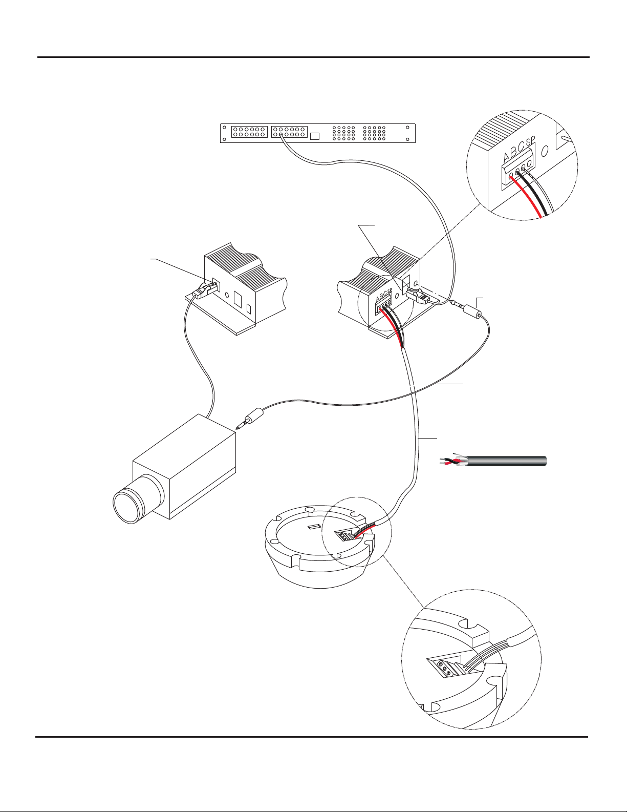
3. Microphone Connection :
a) Connect a 2 cond. shielded cable to the terminal block of Louroe’s Verifact microphone. Connect the other end to
the pluggable header (Mic/Speaker Audio Terminal Block ) of the IF-PX. Connect terminal A of microphone to
terminal A of IF-PX; terminal B of microphone to terminal B of IF-PX; terminal C of microphone to terminal C of IF-
PX. Terminal SP of IF-PX is not used when connecting microphone only (one-way listen).
b) Using the patch cable (stereo plug to stereo plug), connect the Audio Output Jack of the IF-PX to the audio input
of the camera.
c) Adjust the Mic Out Adjust potentiometer (as needed) by rotating it clockwise to increase the microphone output to
the camera, or counterclockwise to decrease. This potentiometer is factory set for a gain of 0dB output.
4. AOP-SP Connection (two-way audio): Before connecting the AOP-SP series, make sure that the Ethernet
cables between the PSE, IF-PX and Camera are all connected.
a) Connect
(one-way listen)
See
interconnection diagram(Fig 3) on page 4.
a 3 cond shielded cable between the AOP-SP and the pluggable header (Mic/Speaker Audio Terminal
Block) of the IF-PX. Connect terminal A of the AOP-SP to terminal A of IF-PX; connect terminal B of AOP-SP to
terminal B of IF-PX; terminal C of AOP-SP to terminal C of IF-PX and terminal SP of AOP-SP to terminal SP of IF-
PX.
b) Using the patch cable (stereo plug to stereo plug), connect the Audio Output Jack of the IF-PX to the audio input
of the camera or encoder. Connect the Audio Input Jack of IF-PX to audio output of the camera or encoder. See
interconnection diagram on page 5.
c) See installation instructions of AOP-SP for setting up and operation of the unit.
5. Setup camera for video and audio monitoring. Use an amplified speaker and a microphone to test the audio. A push
to talk microphone is recommended to minimize the echo when doing two-way audio. See camera user manual for
setting up the camera to the network.
1. Do not connect non-PoE complaint devices to Power+Data Output Jack . Failure to do so may damage the
powered equipment.
Plan ahead where to install before making any connections.The IF-PX is supplied with 6’ audio cables for connections
between the IF-PX and camera. The maximum distance between the IP camera and PSE is 100m or 328’.
2. Do not connect wiring from external microphone or AOP-SP to the Mic/Speaker Audio Terminal Block until
all the ethernet cables (RJ45) are connected and power is present to the camera. Failure to do so in sequence,
the camera may not receive power.
INSTALLATION AND OPERATING INSTRUCTIONS
Page 2 of 8 if-px inst 12/12
LOUROE ELECTRONICS® 6 9 5 5 VA L J E A N AVENUE, VAN NUYS, CA 91406 TEL (818) 994-6498 FAX 994-6458
(818)
CAUTION
NOTES
CONNECTIONS AND OPERATIONS
5
The IF-PX can power most IP cameras and Encoders, check that the power requirements of the equipment does
not go beyond the IF-PX power output. See IF-PX power output below.
Power output of IF-PX:
12Vdc, 650mA with AOP-SP connected
12Vdc, 850mA with a Louroe microphone only connected
CONNECTING PoE SWITCH TO NON-PoE IP CAMERA OR ENCODER (See Fig 5)
1. Connect Ethernet cable from PSE (Power Source Equipment) to the Power+Data Input Jack of the IF-PX.
2. Connect Ethernet cable from camera to Data Out Only Jack of the IF-PX.
8
1
1
5
9
2
5
9
8
7
6

Page 3 of 8
LOUROE ELECTRONICS® 6 9 5 5 VA L J E A N AVENUE, VAN NUYS, CA 91406 TEL (818) 994-6498 FAX 994-6458
(818)
INSTALLATION AND OPERATING INSTRUCTIONS
if-px inst 12/12
SPECIFICATIONS
Ethernet Connectors
Voltage Input
DC Output
Operating Temperature
RJ45 CAT 5 Input and Output Jacks
12Vdc, 800mA
-20°C to +65°C
Optional Power Supply 12Vdc, 2A, Ext. Power Supply
(Not Supplied)
Connectors
Audio Output/Input
Audio Output Gain
Material
up to +15dB
Black Anodized Al 14 Ga
Line level
RJ-45, DC Jack,
Terminal Block for Microphone/Speaker
3.5mm Stereo Jacks for Audio IN/OUT
Dimensions
Weight 13oz.
6”L x 3 1/2”W x 2 1/8”H
36V - 57V
CONNECTING NON-PoE SWITCH TO NON-PoE CAMERA OR ENCODER (See Fig. 6 - Encoder shown)
1. Connect Ethernet cable from Non-PoE Switch to the Power+Data Input Jack of the IF-PX.
2. Connect Ethernet cable from Encoder or Camera to Data Out Only Jack of the IF-PX.
3. Connect DC Out Terminal Block to the power input jack of the encoder or camera. This Terminal block supplies
12Vdc power to the camera or encoder. It can also provide power to other external equipment such relays, etc. that
require a 12Vdc power. Connect 2 wires to the DC Out Terminal Block . At least 20 AWG wires can be use between
the IF-PX and the encoder or camera. Positive 12Vdc connects to terminal marked “+12Vdc” of IF-PX. Negative 12Vdc
or ground connects to terminal marked “GND”of IF-PX. Connect the other end of the 2 wires to the power jack or
terminal block of the encoder or camera. If the encoder or camera has a 2.1mm power jack, an adapter (2-pin terminal
block to 2.1mm male plug) can be used. Connect the wires to the 2-pin terminal block (observe polarity) of the
adapter. Plug the adapter to the 2.1mm power jack of the encoder or camera.
4. Connect an external power supply (not included) to the DC In Jack to power the IF-PX and the encoder or camera.
We recommend using a 12Vdc, 2A power supply.
5. Repeat same procedure when connecting Louroe Verifact microphone or AOP-SP (steps 3 thru 5 from the previous
page - Connections and Operations).
8
7
3
3
4
3. Connect 2 wires to the DC Out Terminal Block . At least 20 AWG wires should be used between the IF-PX and the
encoder or camera. Positive 12Vdc connects to terminal marked “+12Vdc” of IF-PX. Negative 12Vdc or ground
connects to terminal marked “GND” of IF-PX. Connect the other end of the 2 wires to the power jack or terminal block
of the encoder or camera. If the encoder or camera has a 2.1mm power jack, an adapter (2-pin terminal block to
2.1mm male plug) can be used. Connect the wires to the 2-pin terminal block (observe polarity) of the adapter. Plug
the adapter to the 2.1mm power jack of the encoder or camera.
4. Repeat same procedure when connecting Louroe Verifact microphone or AOP-SP (steps 3 thru 5 from the previous
page - Connections and Operations).
3

ABC
C
B
A
POWER+DATA OUT
AUDIO IN
AUDIO OUT
2 COND SHIELDED 22AWG
WITH 24AWG DRAIN WIRE
POWER+DATA IN
PoE (802.3af) SWITCH
INTERCONNECTION DIAGRAM BETWEEN A PoE SWITCH, IF-PX, IP CAMERA
AND VERIFACT A MICROPHONE FOR ADDING ONE-WAY AUDIO
PoE IP CAMERA
VERIFACT A MICROPHONE
IF-PX
INSTALLATION AND OPERATING INSTRUCTIONS
Page 4 of 8 if-px inst 12/12
LOUROE ELECTRONICS® 6 9 5 5 VA L J E A N AVENUE, VAN NUYS, CA 91406 TEL (818) 994-6498 FAX 994-6458
(818)
FIG. 3
3.5MM STEREO PATCH CABLE

POWER+DATA OUT
POWER+DATA IN
AUDIO IN
AUDIO IN
AUDIO OUT
AUDIO OUT
PoE (802.3af) SWITCH
IF-PX
PoE IP CAMERA
AOP-SP-W
3 COND SHIELDED 20AWG
WITH 22AWG DRAIN WIRE
3.5MM STEREO PATCH CABLES
INTERCONNECTION DIAGRAM BETWEEN A PoE SWITCH, IF-PX, IP CAMERA
AND AOP-SP SPEAKER/MICROPHONE UNIT FOR ADDING TWO-WAY AUDIO
Page 5 of 8 if-px inst 12/12
LOUROE ELECTRONICS® 6 9 5 5 VA L J E A N AVENUE, VAN NUYS, CA 91406 TEL (818) 994-6498 FAX 994-6458
(818)
INSTALLATION AND OPERATING INSTRUCTIONS
FIG. 4

Page 6 of 8
LOUROE ELECTRONICS® 6 9 5 5 VA L J E A N AVENUE, VAN NUYS, CA 91406 TEL (818) 994-6498 FAX 994-6458
(818)
INSTALLATION AND OPERATING INSTRUCTIONS
FIG. 5
INTERCONNECTION DIAGRAM BETWEEN A PoE SWITCH, IF-PX, NON-PoE ENCODER
AND AOP-SP SPEAKER/MICROPHONE UNIT FOR ADDING TWO-WAY AUDIO
(WHEN USING LOUROE MICROPHONE FOR ONE-WAY LISTEN, JUST CONNECT ONLY
THE AUDIO OUTPUT OF THE IF-PX TO THE AUDIO INPUT OF CAMERA OR ENCODER)
PoE (802.3af) SWITCH
AUDIO OUT
AUDIO IN
20AWG 2 COND CABLE
POWER CONNECTIONS:
+12Vdc connects to +12VDC of Camera/Encoder
GND connects to negative or Ground of Camera/Encoder
12VDC OUTPUT
(OBSERVE POLARITY)
DC OUT
GND +12VDC
AUDIO OUT
AUDIO IN
3 COND SHIELDED 20GA WITH 22GA DRAIN WIRE
( FOR ONE-WAY LISTEN MICROPHONE ONLY, USE
2 COND SHIELDED 22GA WITH 24GA DRAIN WIRE)
DATA ONLY OUT
POWER+DATA IN
AUDIO
DATAOUT
LAN
DC IN
IN OUT
VIDEO IN
REAR OF IF-PX
NON PoE ENCODER
OR
CAMERA
FRONT OF IF-PX
ANALOG CAMERA
AOP-SP
12VDC INPUT
if-px inst 12/12
3.5MM STEREO PATCH CABLES

Page 7 of 8
LOUROE ELECTRONICS® 6 9 5 5 VA L J E A N AVENUE, VAN NUYS, CA 91406 TEL (818) 994-6498 FAX 994-6458
(818)
INSTALLATION AND OPERATING INSTRUCTIONS
INTERCONNECTION DIAGRAM BETWEEN A NON-PoE SWITCH, IF-PX, NON-PoE ENCODER
AND AOP-SP SPEAKER/MICROPHONE UNIT FOR ADDING TWO-WAY AUDIO
(WHEN USING LOUROE MICROPHONE FOR ONE-WAY LISTEN, JUST CONNECT ONLY
THE AUDIO OUTPUT OF THE IF-PX TO THE AUDIO INPUT OF CAMERA OR ENCODER)
NON-PoE SWITCH
AUDIO OUT
AUDIO IN
12VDC OUTPUT
(OBSERVE POLARITY)
NOTE:
POWER TO THE ENCODER IS SUPPLIED
BY THE IF-PX THRU AN EXTERNAL
POWER SUPPLY SHOWN
DC OUT
DC IN
GND +12VDC
AUDIO OUT
AUDIO IN
3 COND SHIELDED 20GA WITH 22GA DRAIN WIRE
( FOR ONE-WAY LISTEN MICROPHONE ONLY, USE
2 COND SHIELDED 22GA WITH 24GA DRAIN WIRE)
DATA OUT ONLY
DATA IN ONLY
AUDIO
DATAOUT
LAN
DC IN
IN OUT
VIDEO IN
REAR OF IF-PX
FRONT OF IF-PX
ANALOG CAMERA
12VDC, 2A EXTERNAL
POWER SUPPLY
(NOT SUPPLIED)
AOP-SP
12VDC INPUT
if-px inst 12/12
FIG. 6
3.5MM STEREO PATCH CABLES
POWER CONNECTIONS:
+12Vdc connects to +12VDC of Camera/Encoder
GND connects to negative or Ground of Camera/Encoder
NON PoE ENCODER
OR
CAMERA

WARRANTY
LOUROE ELECTRONICS® warrants that at the time of shipment products manufactured by LOUROE ELECTRONICS® to be free of defects in material and workmanship.
Should a defect appear within one year (12 months) from date of shipment, LOUROE ELECTRONICS® will, at its sole discretion, repair or replace the defective equipment.
This equipment shall not be accepted for repair or return without prior notification by LOUROE ELECTRONICS®.
This warranty does not extend to any Louroe product that has been subjected to improper or incorrect installation, misuse, accident, or in violation of installation
instructions provided by LOUROE ELECTRONICS®.
Returned shipments to LOUROE ELECTRONICS® shall be at customer’s expense. LOUROE ELECTRONICS® will return the equipment prepaid via best way.
Page 8 of 8
LOUROE ELECTRONICS® 6 9 5 5 VA L J E A N AVENUE, VAN NUYS, CA 91406 TEL (818) 994-6498 FAX 994-6458
(818)
INSTALLATION AND OPERATING INSTRUCTIONS
if-px inst 12/12
MANUFACTURED
IN THE
IMPORTANT NOTICE
When this equipment is used as part of an audio
monitoring system, the law requires that the public be
given notice of AUDIO MONITORING ON THE
PREMISES. A decal notice is included with each
microphone shipped.
Federal Law References:
Federal Regulations, US Code, Title 18. Crime and
Criminal Procedure, Sec 2510.
AUDIO
MONITORING
On
These Premises
TM
Table of contents
Other Louroe Electronics Recording Equipment manuals