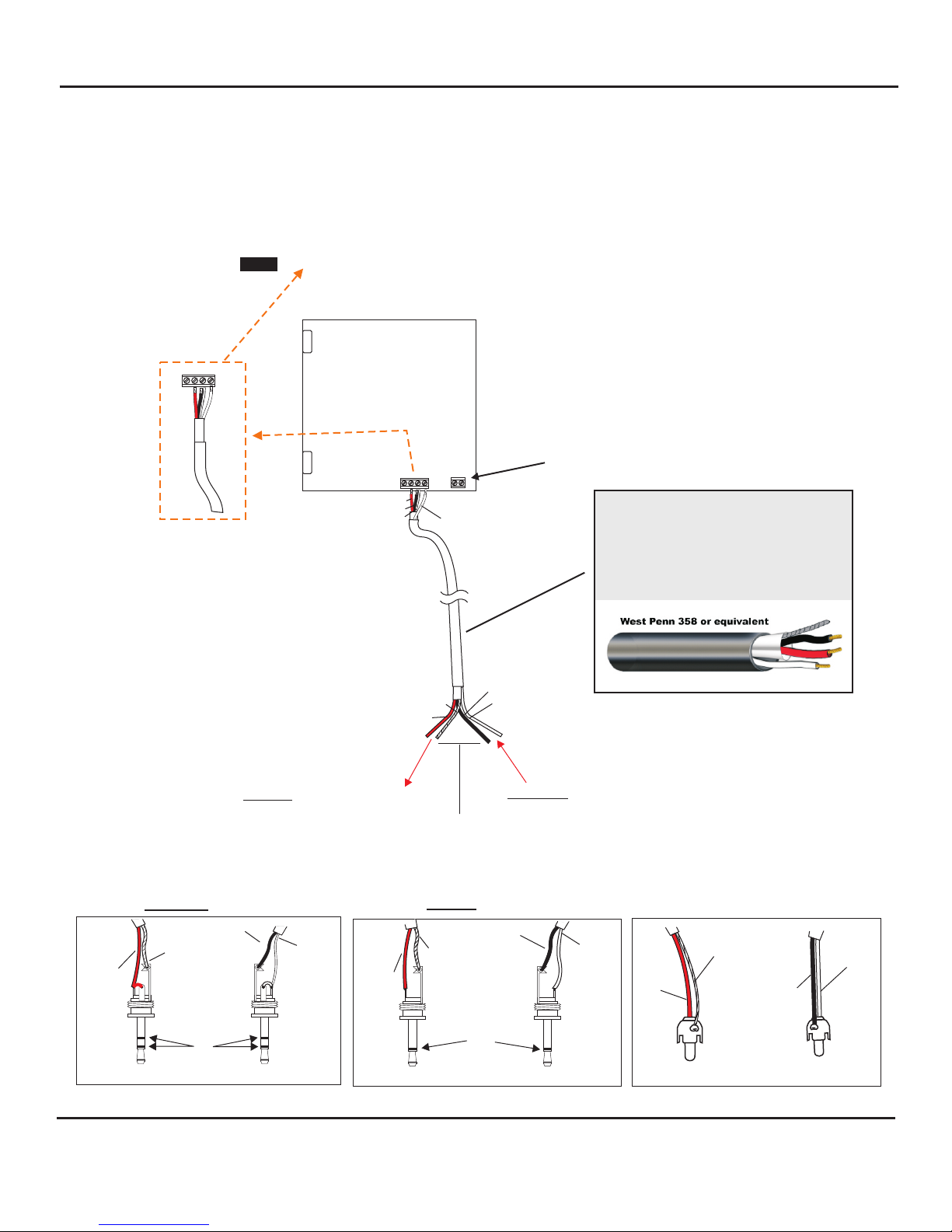
Color Code of recommended wiring is:
RED - 12Vdc power to microphone
BLACK - Audio Output
BARE - Ground
WHITE - Speaker
Color Code may vary among wire manufacturers
block marked A, B, C, SP
A = 12Vdc power (red wire)
B = Audio output (black wire)
C = Ground (bare wire)
SP = Speaker Connection (white wire)
Bring one end of recommended cable and connect as follows:
Located on the bottom right side of PC board is a 4-pin terminal
WIRING CONNECTION TO SPEAKER AND MICROPHONE OF AOP-SP CF/CS
WIRING CONNECTION TO AOP-SP (CF OR CS Models)
WIRING CONNECTION FROM AOP-SP-CF OR AOP-SP-CS TO
COMPANION AOP-XD AUDIO INTERFACE UNIT
1) Connect RED wire to terminal marked “A”
2) Connect BLACK wire to terminal marked “B”
3) Connect BARE wire to terminal marked “C“
4) Connect WHITE wire to terminal marked “SP“
The rear panel of the AOP-XD has a 4-pin terminal block marked A, B, C, SP
Bring in other end of cable and connect as follows:
1) Red wire to terminal A of AOP-XD
2) Black wire to terminal B of AOP-XD
3) Bare wire to terminal C of AOP-XD
4) White wire to terminal SP of AOP-XD
On the back panel of Model AOP-XD is a set of Audio In/Audio Out Jacks - RCA type.
If the input of the receiving device is 3.5mm Mono jack, a pair of RCA to 3.5mm Mono adaptor is supplied.
Using the appropriate patch cables, connect as follows:
1) Audio Out of AOP-XD connects to Audio In of receiving device
2) Audio In of AOP-XD connects to Audio Out of receiving device
This completes the wiring between the AOP-SP-CF/AOP-SP-CS and AOP-XD. For operation instructions
regarding Model AOP-XD Transceiver Interface Unit, refer to the AOP-XD instructions that accompany the unit.
See diagram next page
WIRING REQUIREMENTS
3 Conductor consisting of:
+
2 Conductor shielded, 20 gauge
with 22 gauge drain
+
1 Conductor unshielded, 20 gauge
All in the same jacket
See diagram next page
CONNECTION FROM AOP-XD TO THE RECEIVING DEVICE (DVR, IP CAMERA, ETC.)
Page 2 of 8
INSTALLATION AND OPERATING INSTRUCTIONS
aopsp cf/cs inst 03/11
LOUROE ELECTRONICS 6 9 5 5 VA L J E A N AVENUE, VAN NUYS, CA 91406 TEL (818) 994-6498 FAX 994-6458
(818)
®