CONNECTING MODEL TLI TO LOUROE AUDIO BASE STATION
The audio inputs differ among the various Louroe base stations. Refer to the installation instructions
for the specific model base station.
NOTE: IF USING CABLE FROM OTHER MANUFACTURERS, COLOR CODE MAY
SENSITIVITY SWITCH OF TLI MICROPHONE
For special installations that require less microphone sensitivity, a sensitivity switch is located at the
top right corner of the PC board and has two positions, N (normal) and L (low). Factory set at “N”.
Use small screwdriver to move slide switch to L position (low sensitivity).
INSTALLATION AND OPERATING INSTRUCTIONS
Page 3 of 8
LOUROE ELECTRONICS 6 9 5 5 VA L J E A N AVENUE, VAN NUYS, CA 91406 TEL (818) 994-6498 FAX 994-6458
(818)
®
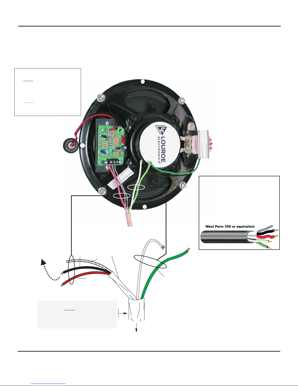
MICROPHONE CONNECTION (SEE DIAGRAM PAGE 4):
Connection to the microphone is thru the Terminal block of the pcboard mounted on the speaker and is labeled
A, B, C. Using West Penn 356 or equivalent four conductor cable, connect as follows:
1) Connect RED wire (shielded) to terminal block marked “A” (12 Vdc supply)
2) Connect BLACK wire (shielded) to terminal block marked “B” (audio)
3) Connect DRAIN wire (bare) to terminal block marked “C” (ground)
SPEAKER CONNECTION :
Using wire nuts, connect speaker wires as follows:
1) Black wire of TLI connects to the White wire of West Penn356 (common)
2) Green wire of TLI connects to Green wire of West Penn 356
(SEE DIAGRAM PAGE 4)
TLI_Series_inst_3/15
Shipping Weight
TLI-CS Weight
TLI-CS Shipping Weight
TLI-CF Weight
TLI-VR-F Weight
TLI-VR-SQ Weight
TLI-CF Shipping Weight
TLI-VR-F Shipping Weight
TLI-VR-SQ Shipping Weight
1 lb 11 oz
4 lbs
2 lbs 10 oz
7 lbs
2 lbs
3 lbs x 10 oz
5 lbs 14 oz
6 lbs
8 lbs
10 lbs
SPECIFICATIONS (Speaker)
SPECIFICATIONS (Mechanical)
Power rating
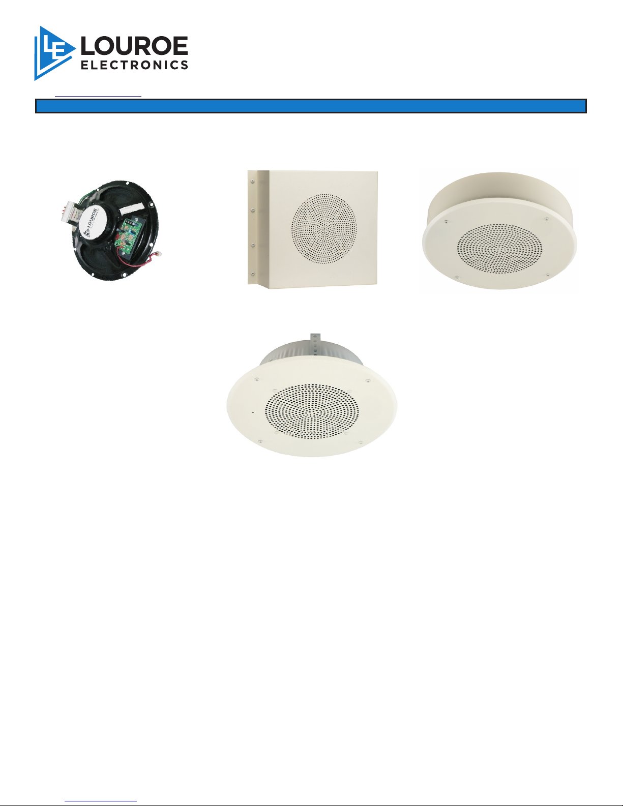
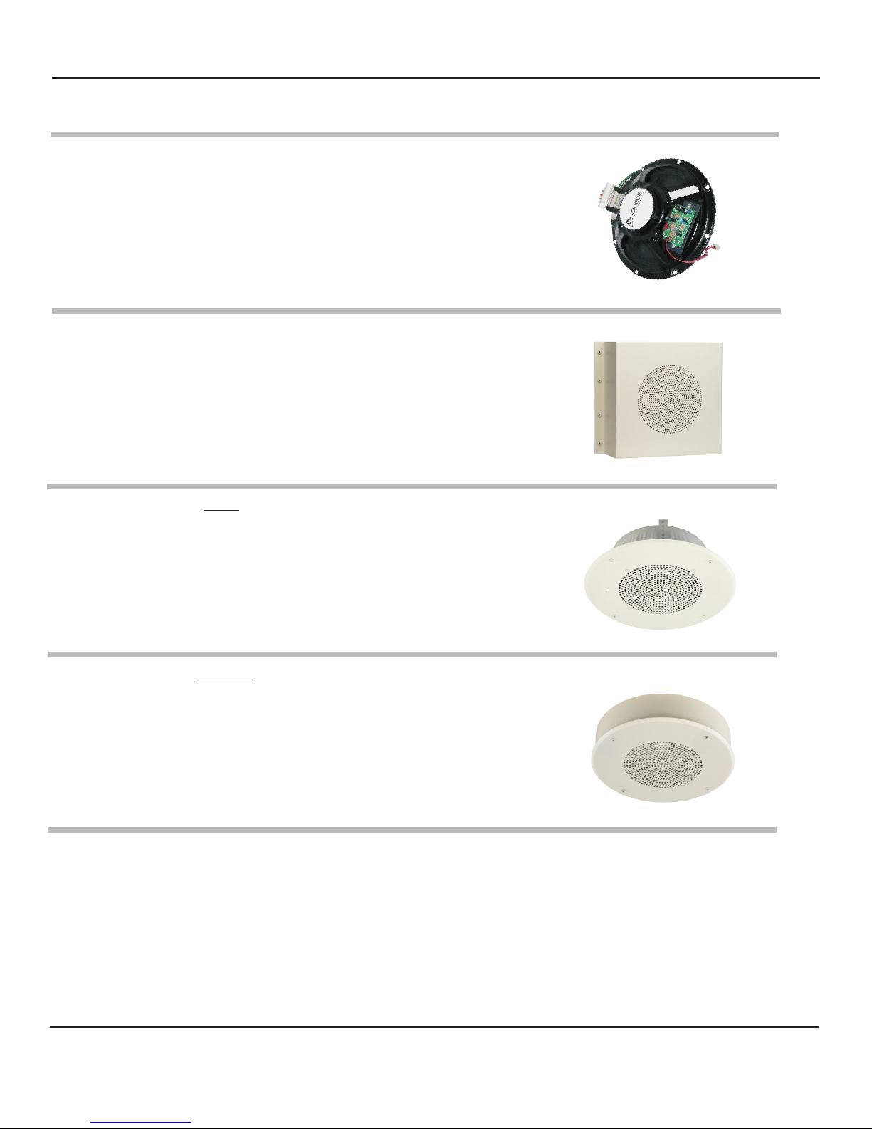
TLI (No housing)
Input
TLI-CS/TLI-CF/TLI-VR-F Faceplate
with Speaker and microphone
Frequency response
Voice coil impedance
ERD-8 (Backbox for TLI-CF)
15W
8” Dia x 2 5/8” D
70.7V constant
12 7/8” Dia x 2 3/4” D
65 Hz to 17 kHz
8
12 1/4” Dia x 4” D
Speaker size
MR-8 (Mounting ring for TLI-CS)
TLI-VR-SQ
8”
12 3/8” Dia x 3” D
13” H x 11” W x 4” D
TLI (No housing) Weight
Sensitivity -45 dBV/Pa
1 Pa = 94 dB SPL
Frequency Response 50 Hz to 15 kHz
Output Line Level (0 dBV, 600W@ 1kHz)
Current Drain 10mA
Supply Voltage 12 Vdc
SPECIFICATIONS (MICROPHONE)