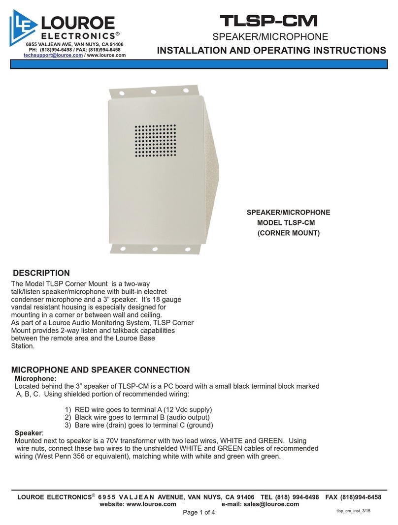
PAGE 1 OF 4
MICROPHONE AND SPEAKER CONNECTIONS
MICROPHONE AND SPEAKER CONNECTIONS
Using West Penn 356 as an example cable (see connection diagram, page 3) connect cable as
follows:
If using wiring from other manufacturers, color code may vary
MICROPHONE CONNECTION
1) Connect RED wire to terminal block marked “A” (+12Vdc)
2) Connect BLA CK wire to terminal block marked “B” (Audio Output)
3) Connect DRAIN wire (bare) to terminal blocked marked “C “ (Ground)
SPEAKER CONNECTION
1) Using a wire nut, connect GREEN wire (positive) to GREEN wire connected to speaker
transformer
2) Again using a wire nut, connect WHITE wire (negative) to WHITE wire connected to speaker
transformer.
TLM CONNECTION TO LOUROE AUDIO BASE STATION
Most Louroe base stations contain terminal blocks on the rear panel and are the same or similar to
the TLM-CF or TLM-CS. Carefully match pins A to A, B to B, etc. Refer to the base station
instructions that accompany TLM instructions.
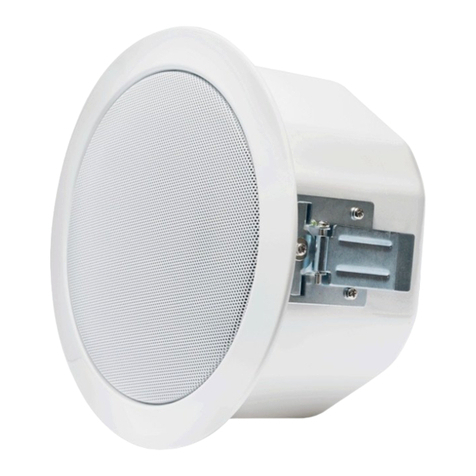
The Model TLM-CF/TLM-CS are ceiling mount
speaker/microphones consisting of an electret
condenser microphone and 4” speaker, all within
one housing. As part of a Louroe audio monitoring
system, they provide two-way talk/listen
communication between the remote area and the
Louroe audio base station.
Model TLM-CF is for flush mounting to the ceiling
and includes:
TLM speaker and microphone assy
BR-4 grill
ERD-4 back box
Model TLM-CS is for surface mounting to the
ceiling and includes:
TLM speaker and microphone assy
BR-4 grill
MR-4 Mounting ring
LOUROE ELECTRONICS 6955 VALJEAN AVE, VAN NUYS, CA 91406 TEL (818) 994-6498 FAX 994-6458
(818)
WIRING REQUIREMENTS
4 Conductor consisting of:
+
2 Conductor shielded, 20 gauge
with 22 gauge drain (microphone
connection)
+
2 Conductor unshielded, 18 gauge
(speaker connection)
All in the same jacket
West Penn 356 or equivalent
TLM 1/08
INSTALLATION AND OPERATING INSTRUCTIONS
