Doc: I437GB04_16.docx 09/03/2016 p. 3 / 37
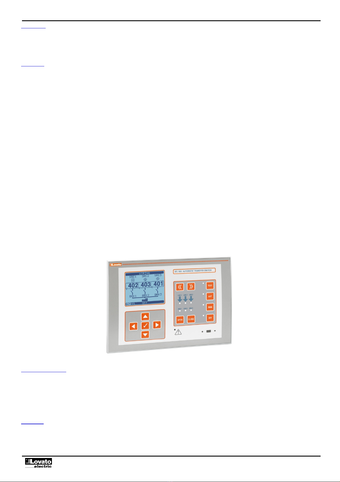
BRK1 switch state LED (yellow) - When fixed, indicates the open or closed state of line breaker 1 (BRK1). When blinking, indicates incoherence between required state of the
breaker and real state detected by the feedback signal.
BRK2 switch state LED (yellow) - When fixed, indicates the open or closed state of line breaker 2 (BRK2). When blinking, indicates incoherence between required state of the
breaker and real state detected by the feedback signal.
BRK3 switch state LED (yellow) - When fixed, indicates the open or closed state of line breaker 3 (BRK3). When blinking, indicates incoherence between required state of the
breaker and real state detected by the feedback signal.
Operating modes
OFF mode - The equipment is off and no actions are performed in this mode. All measurement and state LED displays remain active. If the transfer device control is of the pulse
type, both open/close controls remains deactivated in OFF mode. In continuous control mode, instead, the behaviour may be selected by means of P07.n.06. Set to OFF mode
before accessing the programming menus. Press the OFF-RESET button to reset the retaining alarms providing the conditions which generated the alarm have been removed.
MAN (manual) mode - The breakers can be controlled manually in manual mode. The breaker to be controlled can be selected on the display by pressing buttons << and >>. The
selected breaker appears surrounded by a blinking box. Press the OPEN and CLOSE buttons to change the selected breaker state.
If the closing of a breaker is manually controlled while one other breaker is still closed, the equipment will not allow the simultaneous closing.
When working with gensets, the starting and stopping of the genset can be manually controlled in the manner similar to that of the breakers. In this case, the MAN button must be
held pressed to start and stop the genset. The genset corresponding to the breaker highlighted by the blinking box will be started.
AUT (Automatic) mode - In automatic mode, the equipment autonomously carries out the opening and closing operations of the breakers and to start and stop any gensets. When
the priority line is out of limits for a time higher than the set delay (green line presence LED off), the device disconnects the load from the priority line and connects to the
immediately next priority line, starting of the genset (if applicable) and managing the operation and interlock times. The equipment can be programmed to open the priority line
breaker either before or after the alternative line is made available .
When the priority line return within the limits, the device switches the load back onto it and runs the genset cooling cycle, if needed. The automatic return to priority lines can be
locked. If possible and necessary, the load can be transferred with closed transition, i.e. with the two power sources momentarily in parallel. There are very many automatic
operating cycles which vary according to the defined system configuration (14 possibilities) and according to the type of transfer devices used (motorised breakers, motorised
changeover switches or contactors). Refer to the possible system configurations and the respective truth tables which describe the system behaviour in automatic mode.
Note: The use of closed transition function is not compatible with compliance with IEC / EN 60947-6-1.
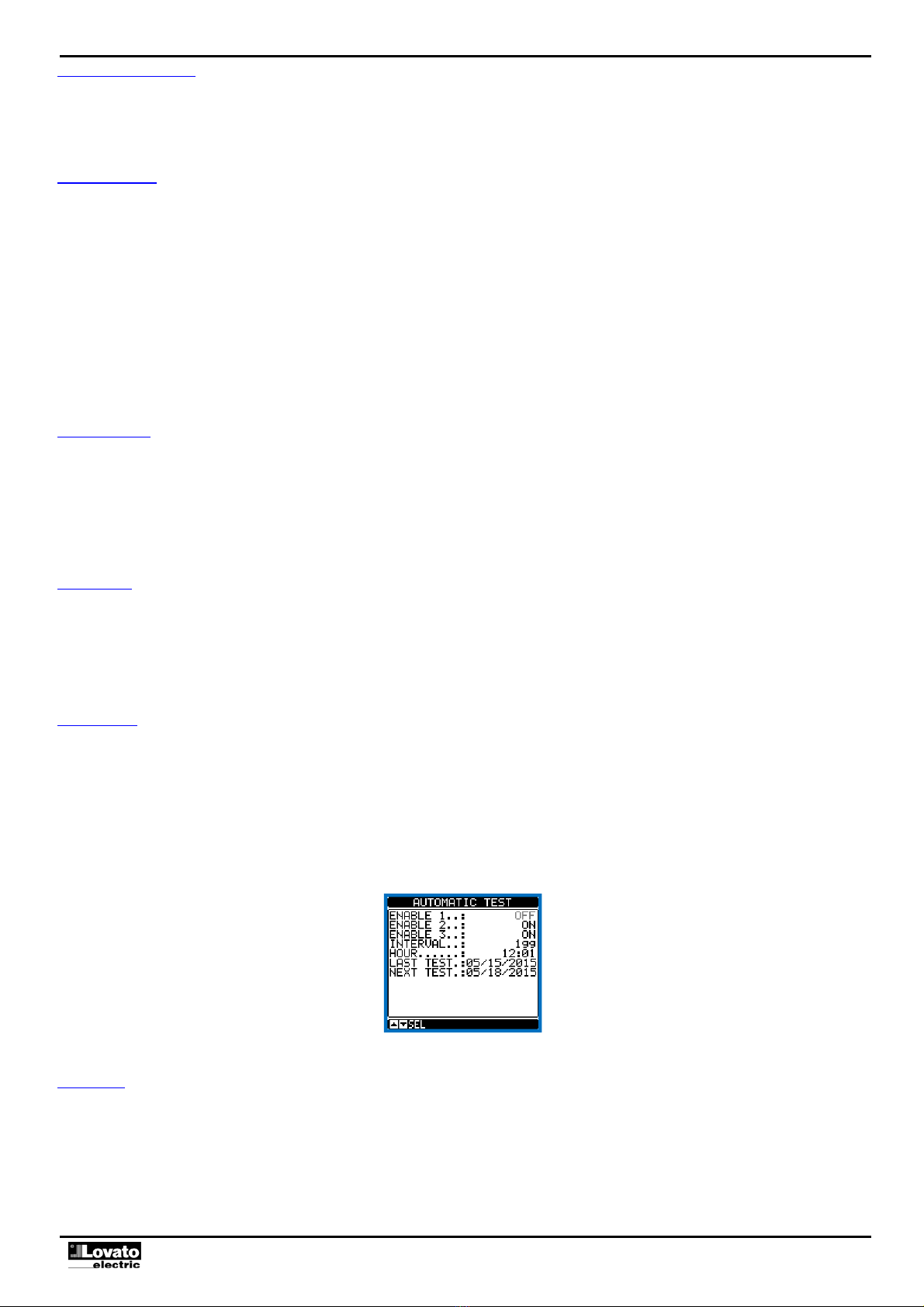
TEST mode - In test mode, the equipment starts the gensets, if present, to test their operation. If the TEST button is held pressed for 5 seconds, the equipment will run a cycle
which simulates loss of the priority line anticipated by a notification message with consequent load transfer. Caution: this will momentarily interrupt power supply to the load. Lack
of the secondary line is then simulated with the further transfer to the third line, if present. Two minutes later, the cycle will go back to the secondary line and finally to the main line
in sequence. During this cycle, the message SIMUL appears on the display with a countdown to indicate TEST progress. The simulation cycle may be started on the command
menu.
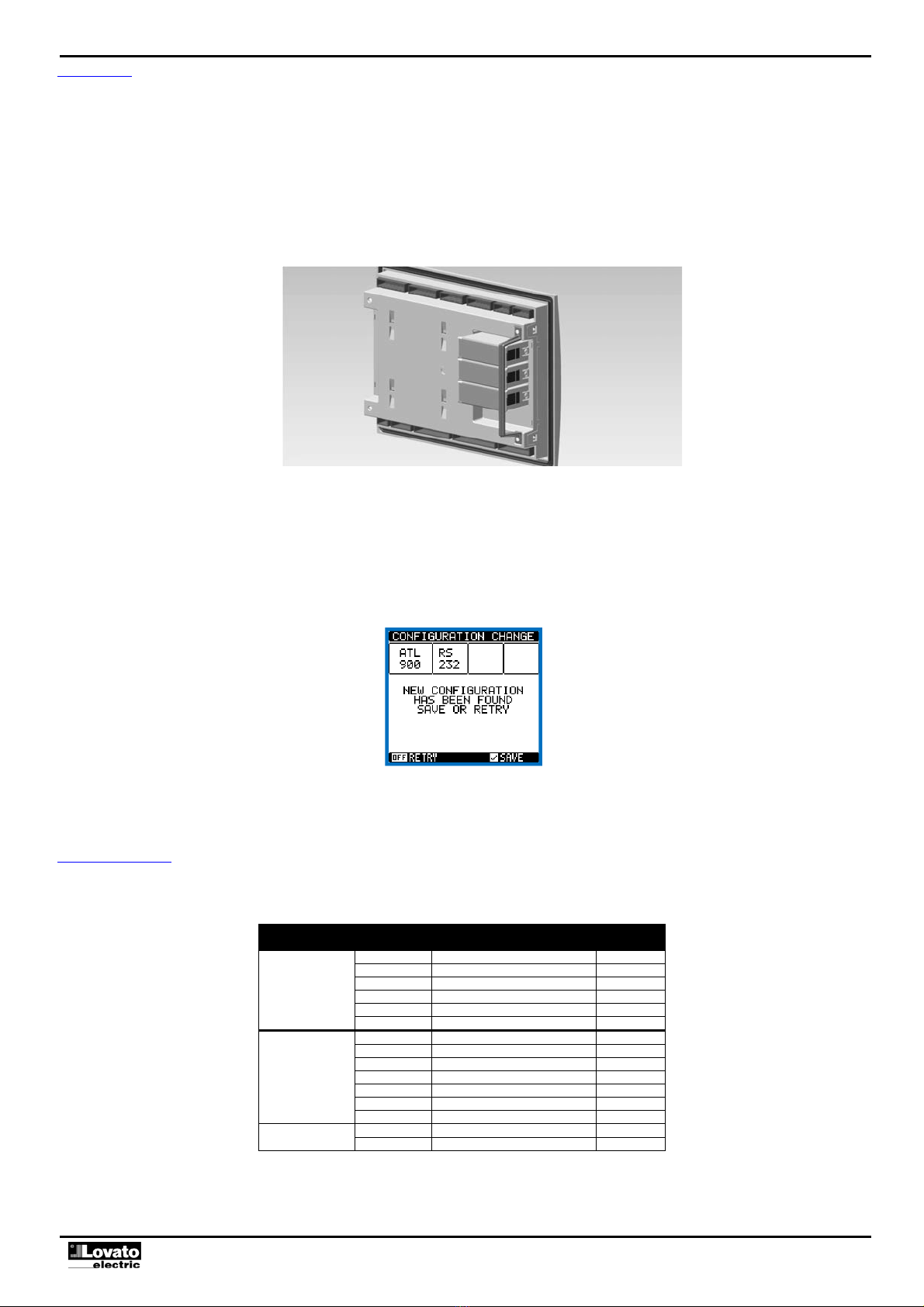
Energising the equipment
ATL900 has two power supplies: 100-240VAC or 12-24-48VDC. Priority is given to the AC power if both are present at the same time.
The equipment is normally set to the OFF mode when it is switched on. Modify parameter P01.03 in the M01 Utility menu if the operating mode selected before switch-off must
be maintained.
If may be powered at 12 or at 48VDC but the battery voltage must be set correctly in the M04 battery menu otherwise a battery voltage alarm will be generated.
All LEDs blink during the energising procedure to check operation.
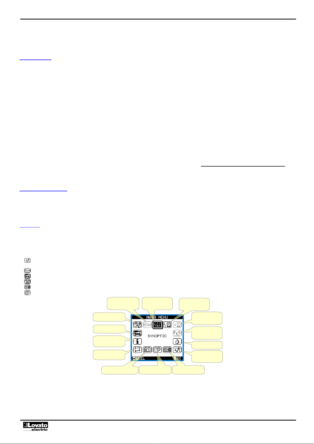
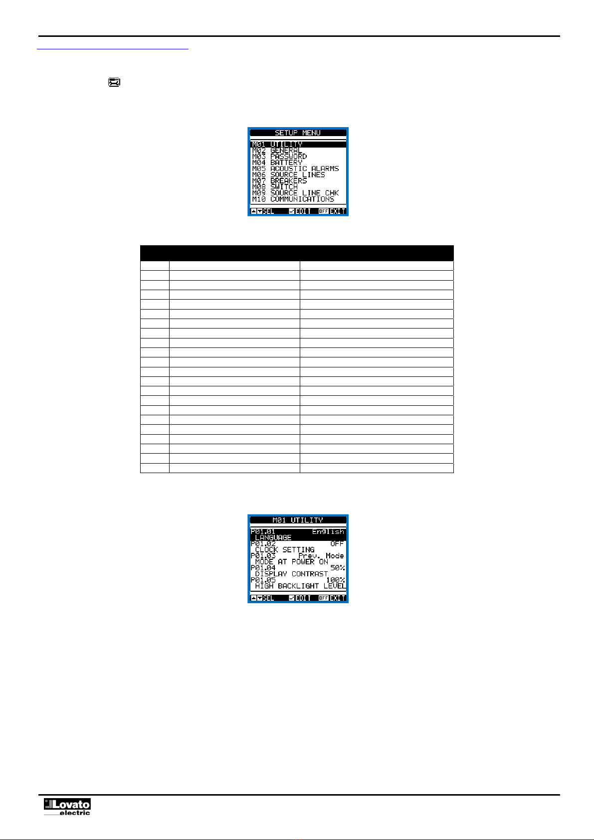
Main menu
The main menu consists of a set of graphic icons which allow rapid access to measurements and settings.
Press button starting from the normal measurement view. The rapid menu appears on the display.
Press ◄or ►to turn clockwise/anticlockwise and select the required function. The selected icon is highlighted and the message in the middle of the display indicates the
description of the function.
Press to activate the selected function.
If some functions are not available, the corresponding icon will be deactivated, i.e. will greyed out.
etc. - Operate as short cuts which allow to speed up access to pages for displaying measurements, going directly to the selected measurement unit, from which it is
possible to move forwards and backwards are usual.
- Setting the numeric code which allows to access protected functions (setting parameters, executing controls).
- Parameter programming access point. See the dedicated chapter.
- Control menu access point, where authorised users can perform a number of resetting and restoring operations.
- Access point to statistic operating data supplied by the controller.
- Access point to the events list.
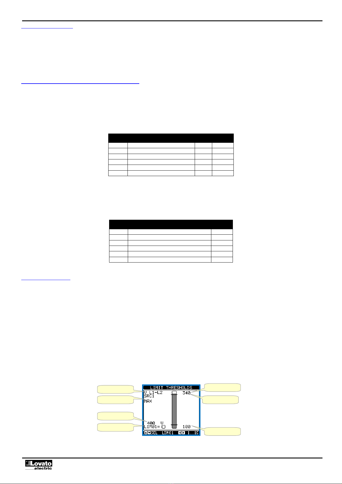
Control thresholds
StatisticsEvents log
Battery state
Input/output state
Information page
Setup parameters
Control menu
Password entry Synoptic Voltages
Currents
Powers
Alarms