OPERATION
Battery Installation
The unit is shipped with a 9 V alkaline battery which must be installed before operation.
When battery replacement becomes necessary, use only a 9 V alkaline type. To install
the batteries:
1. Remove the screw holding the back cap in place.
2. Connect the battery to the enclosed battery clip observing correct polarity. Be
careful not to trap wires between the battery or case. This could make it difcult to
install the battery or remove it later for replacement.
3. Replace the back cap and screw into place.
Pressure Connectors
The LDPM has two barbed connector ports for use with 1/8˝ (3.18 mm) or 3/16˝ (4.76
mm) ID tubing.
• For a single positive pressure, connect the tubing to the high pressure
port and vent the opposite to atmosphere.
• For a single negative pressure (vacuum), connect the tubing to the low
pressure port and vent the opposite port to atmosphere.
• To measure differential pressure, connect the higher pressure to the high
pressure port and the lower pressure to the low pressure port. The
manometer will indicate the difference between the two ports. (Note: If pressures
are reversed, LCD will display differential pressure as negative.
On/Off Power
Press the ON/OFF button to turn the unit on or off. Upon startup, the manometer
defaults to the setting last used.
Zeroing Readings
Before use and without ttings attached to the meter, press the HOLD button for more
than 2 seconds to zero the meter. The meter will reset and display 000 from right to
left. 0.000 will be displayed.
Offsetting the Display Value
To offset the meter and display, press the DIF button while taking a measurement. The
subsequent reading will be the difference between the current measurement and the
measurement that was on the display when the button was pressed. Press the DIF
*DIF button photo* button again to turn off this setting.
Display Backlight
Press the BACKLIGHT button to turn on the backlight. It will remain on for 40
seconds or until the BACKLIGHT button is pressed again.
Display Hold
To hold or freeze a value, press the HOLD button momentarily and the HOLD icon
will appear in the upper left side of the display. When the Hold function is enabled, the
pressure reading will not change and the unit of measure and HOLD icon will also be
displayed. Press the HOLD button again to return to normal operation.
Unit Measurement Mode
The manometer features a variety of engineering units to read pressure. Press the
UNITS button momentarily and the manometer will cycle through the 11 available units
of measure as indicated by the cursor on the bottom of the display.
©Copyright 2018 Dwyer Instruments, Inc. Printed in U.S.A. 5/18 FR# 444381-00 Rev. 2
A DIVISION OF
DWYER INSTRUMENTS, INC.
Statistics
The MAX/MIN mode allows the user to view only the highest (MAX), lowest (MIN), or
average (AVG) readings with a relative time stamp of the recorded values.
1. Press the REC button once and REC appears on the display. (All other functions
are locked except for Power and Backlight.) The relative clock also appears in the
secondary display and starts counting.
2. Press the REC button again and MAX appears on the display. The display is now
showing the maximum pressure and relative time it was recorded.
3. Press the REC button to display the minimum value MIN reading with the relative
time.
4. Press the REC button to display the average value AVG reading with the relative
time.
5. Press the REC button again to continue recording MIN/MAX/AVG measurements.
6. To exit the MIN/MAX/AVG mode, press the REC button for 3 seconds to return to
normal operation.
Auto Power Off
The manometer will automatically shut off after 20 minutes to conserve battery life.
To disable the Auto Power Off function, while the unit is off, hold down the HOLD
button and turn on the manometer. An “n” will appear on the display indicating that
Auto Power Off mode is disabled. The manometer will return to normal operation when
it is turned off.
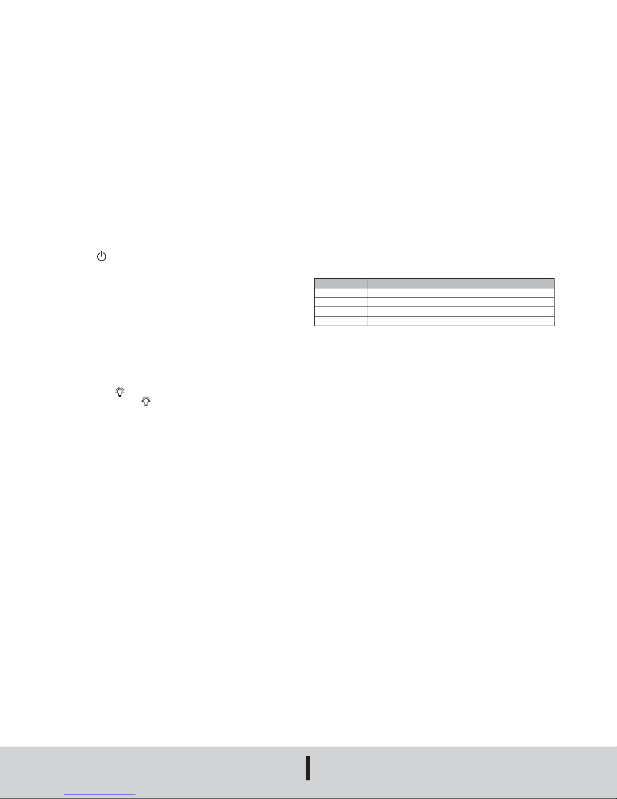
Error Codes
An error message will appear on the display if the manometer fails an internal
diagnostic test.
Battery Monitor
The LDPM monitors its battery voltage whenever it’s powered on. When the battery
power becomes low, BAT will appear on the LCD. A weak battery can cause inaccurate
measurements. It is recommended to replace the battery as soon as possible to ensure
top functionality. Do not leave an exhausted battery in the unit due to potential leakage.
MAINTENANCE/REPAIR
Upon nal installation of the Model LDPM Digital Differential Pressure Manometer, no
routine maintenance is required. The Model LDPM is not eld serviceable and is not
possible to repair the unit. Field repair should not be attempted and may void warranty.
WARRANTY/RETURN
Refer to “Terms and Conditions of Sale” in our catalog and on our website. Contact
customer service to receive a Return Goods Authorization number before shipping the
product back for repair. Be sure to include a brief description of the problem plus any
additional application notes.
ERROR CODE REASON
Err. 1 Pressure value is over the positive pressure limit
Err. 2 Pressure value is below the negative pressure limit
Err. 3 Differential pressure is over the positive pressure limit
Err. 4 Differential pressure is below the negative pressure limit
lovecontrols.com
LOVE CONTROLS
P.O. BOX 373 • MICHIGAN CITY, INDIANA 46360, U.S.A.
Phone: 219/879-8000
Fax: 219/872-9057


