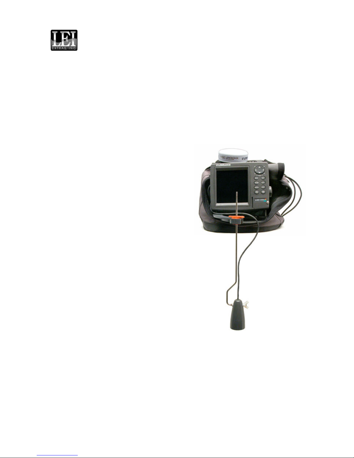
Lowrance 16i User manual

1
PPP-16i Portable Power
Pack with transducer and
GPS module installed.
Shown with the LMS-332C.
Pub. 988-0154-261
PPP-16i
Portable Power Pack
Installation Instructions
This ice fishing power pack is designed for use with most small and
mid-size NMEA 2000compatible Lowranceunits with blue connec-
tors. For complete details on compatible units, consult your dealer or
the company web site, www.lowrance.com.
Even though it was designed for ice fishing, the power pack can also ex-
tend the use of your sonar or GPS into warm weather angling. It's ideal
for fishing from a dock or pier. Crappie
fishermen who tie up to drowned trees
will find the PPP-16i useful for that type
of stationary fishing as well.
With an optional portable Skimmer
transducer, you can run the unit in
your own boat, or take it along as a
second sonar or GPS in a friend's boat.
The versatile sonars compatible with the
PPP-16i have scrolling chart displays as
well as flasher displays, making them
fully functional for boat trolling and
stationary use.
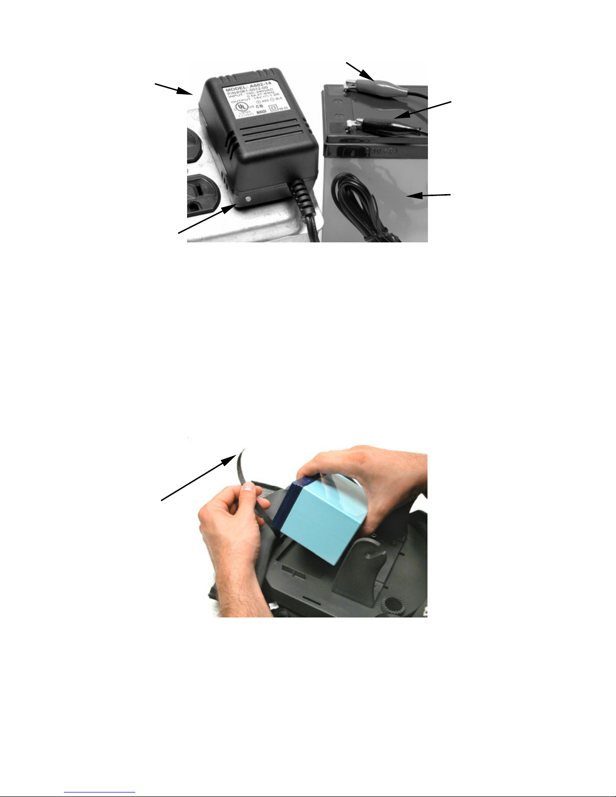
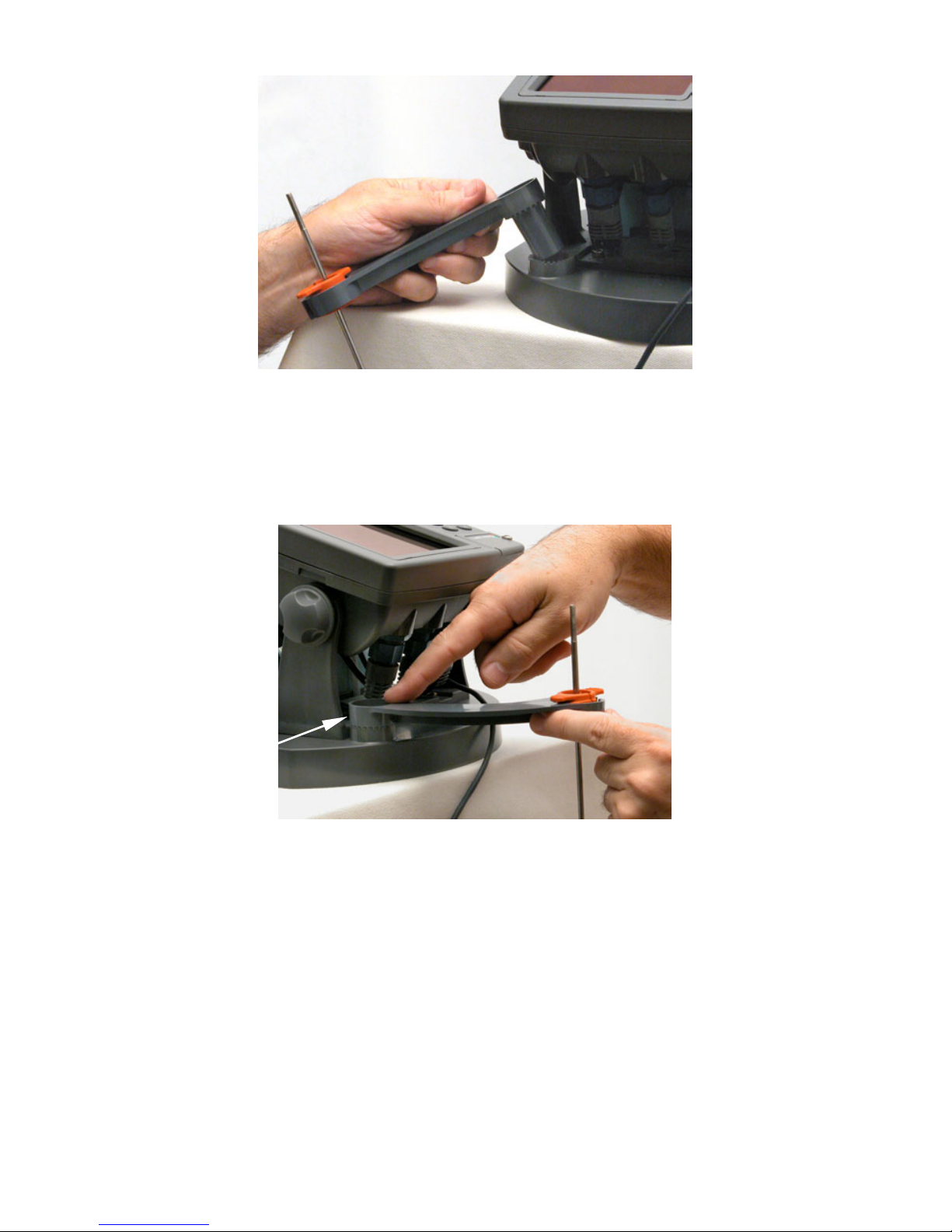
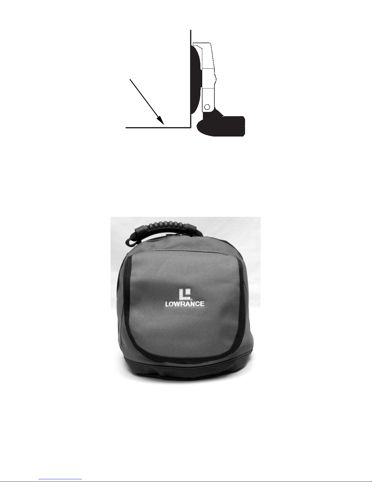
The PPP-16i package includes: freeze
resistant power pack carry bag, base
plate, rechargeable gel cell battery,
battery charger, ice fishing transducer,
transducer mounting rod, swing arm
and adjustment lock for holding the
mounting rod, hook and loop battery
straps and the nuts and bolts needed to
assemble the power pack. The gimbal
bracket is sold separately.
When assembled, the pack is designed to
fit comfortably inside a typical 5-gallon
plastic bucket. This power pack can also use an optional battery
adapter that holds eight "D" size batteries. You can assemble everything
without tools, but it's easiest if you have a screwdriver and perhaps a
small adjustable wrench or pair of wire pliers.

2
MOUNTING BRACKET INSTALLATION
1. Attach the gimbal bracket (sold separately) to the base plate with the
nylon nuts and bolts supplied with the power pack.
Secure gimbal bracket to base plate (left) and slide the battery straps
through the slots on either side of the tray.
2. Slide the hook and loop battery straps through the slots on either
side of the battery tray as shown in the preceding figure. (The two hook
and loop battery straps pack as one piece that you must peel apart.)
BATTERY CARE
Make sure the battery is fully charged before you use the PPP-16i for
the first time. When fully discharged, it takes approximately nine
hours to recharge the battery. Under ordinary operating conditions, the
battery will run your unit with the backlight on for approximately 24
hours before it needs recharging. Battery capacity will vary depending
on air temperature, water depth, backlight settings and the size of the
sonar or GPS you are using.
To charge the battery, plug the charger into a 110 VAC electrical out-
let, then connect the red lead to the red battery contact and the black
lead to the black battery contact. When you first plug in the charger,
the indicator light glows green, which shows it is receiving power. After
you connect the battery, the light will turn red, indicating the battery
is now being charged. When the light turns green again, the battery is
fully charged.
You can recharge the battery after every fishing trip, even if the bat-
tery was not fully discharged. This will keep the unit ready for your
next fishing expedition. Disconnect the battery when stored for long
periods of time.
Hook and loop
battery straps Gimbal bracket
Battery
Nylon nuts and
bolts for bracket

3
The Battery charger's indicator light glows red when charging. It
glows green when the battery is fully charged. To charge the battery,
attach the red connector to the red (positive) contact and the black
connector to the black (negative) contact.
You should also consider charging the battery once a month while in
storage. Most Lowrance units include a display that will show voltage
data, allowing you to monitor how much power the battery is putting
out. Some of the units have a battery capacity indicator, which moni-
tors how much power the battery has left.
BATTERY INSTALLATION
1. Position the battery in the battery tray with the contacts pointed to-
ward the rear of the base plate, away from the gimbal bracket.
Place battery into battery tray.
2. Secure the battery in the tray with the hook and loop battery straps.
3. Attach the power leads from the 3-branched power cable to the bat-
tery contacts or terminals. Connect the red wire to the red/positive
terminal and the black wire to the black/negative terminal. The power
cable's white wire and the data cable's (labeled RS-232 COMM) 4 wires
are unused and should be sealed with electrical tape or a wire nut.
Hook and loop
battery strap
Charger
Red connector
Black
connecto
r
Indicator light
Battery

4
Battery shown connected to sonar unit's power leads.
WARNING:
The sonar or GPS unit must be fused with the enclosed
3-amp fuse (or equivalent). If a malfunction happens in-
side the unit, extensive damage can occur if the enclosed
fuse is not used. As with all electrical devices, the unit
could be damaged to a point where it is unrepairable and
could even cause harm to the user when not properly
fused. Failure to use a 3-amp fuse will void your unit's
warranty.
4. Now, plug the cables into their designated sockets on the back of the
unit. See the following figure.
NOTE:
The socket configuration on the back of your unit may differ from
the examples in this instruction sheet. Refer to the socket labeling
on the back of your unit or the unit's instruction manual for the
correct configuration.
Plugging the transducer cable into the sonar socket on the back of the
unit. The power/data and GPS module cables are already connected.
Each cable has a blue locking collar connector.
Red wire (+)
with fuse
Black wire (-)
Transducer
cable.
3-branch
power/data
cable.
GPS/Network
cable.

5
Optional D cell battery adapter. Connect black to black and red to red.
Caution:
When using the sonar in a saltwater environment, we strongly
recommend you unplug the red and black power connectors from
the battery terminals when the unit is not in use. When the unit
is turned off, but still connected to a power supply, electrolysis
can occur in the power cable plug. This may result in corrosion
of the plug body along with the electrical contacts in the cable
and the unit's power socket.
MOUNTING THE UNIT
1. Attach the sonar unit to the gimbal bracket with the washers and
knobs supplied with the unit. Be sure to slide the rubber washers onto
the knobs first.
When the unit is in the desired position, tighten the gimbal knobs.
2. To adjust the viewing angle, loosen the gimbal knobs, tilt the unit to
the desired position, then retighten the knobs.
Gimbal knobs
Gimbal
bracket
arm
Gimbal
bracket
arm

6
3. Turn on the sonar unit. If it doesn't work, make sure the power leads
are firmly connected to the battery terminals. Also be sure the lead col-
ors match the battery terminal colors (red positive to positive and black
negative to negative).
If it still doesn't work, check the battery voltage. Most complaints about
portable units result from batteries that have not been charged. If you
are using the optional D dry cell battery adapter, be sure you use fresh
batteries. The efficiency of dry cell batteries drops in cold weather. It is
a good idea to have the batteries and the sonar unit nice and warm be-
fore leaving home. (If you are using disposable D batteries, always re-
move them from the power pack when storing the unit because dead bat-
teries can leak, corroding the contacts of the battery adapter.)
If the batteries do lose their charge, you can sometimes restore them by
warming them up. A better option is to replace them with batteries
that have been kept warm.
WARNING:
Never heat batteries over an open flame or direct hot air
onto them. A fire or explosion could result.
MOUNTING THE TRANSDUCER
1. Slip the washer onto the transducer rod, followed by the transducer and
the wing nut.
Assembled transducer, attached to the mounting rod.
2. The wing nut should be tightened enough to hold the transducer on the
rod, but it should be loose enough to allow the transducer to swing freely.
This allows the transducer to self-position itself straight down, for ideal
ice fishing performance.
3. Grasp the assembled transducer and rod in one hand and thread the
swing arm's socket end onto the rod.

7
Insert mounting rod through swing arm's socket, as shown.
4. Snap the red rubber adjustment lock onto the rod and screw it into the
swing arm's threaded socket. As the lock is screwed in, it tightens on the
mounting rod, holding it in place.
Snap adjustment lock onto transducer mounting rod as shown, then
screw it into the swing arm's socket.
If it is too hard to turn, consider adding a small amount of petroleum jelly
or silicone lubricant to the threads on the adjustment lock. This will help
the lock turn more easily, which may be necessary in very cold environ-
ments.
5. Slip the assembled transducer rod and swing arm into the ratcheted
swing arm socket on the front of the base plate.

8
Mount swing arm in ratcheted socket on base plate.
To adjust transducer depth, loosen the adjustment lock, slide the rod up or
down, then retighten. To adjust lateral position in your fishing hole, sim-
ply nudge the arm to one side or another, then lightly press down on the
arm's ratchet end to engage the ratchets. See the following figure.
Adjust transducer position by loosening the red adjustment lock (for
height), or by rotating the swing arm (side to side). Press lightly on the
ratchet end to hold the arm in position and resist lateral movement.
Tip:
When landing a fish, push the arm to one side or just grab the
swing arm, lift it out of your fishing hole and lay it to one side.
OPTIONAL PORTABLE TRANSDUCER ASSEMBLY
Assemble the Skimmer transducer and portable-mounting bracket as
shown in the following illustrations. (Skimmers are available with
built-in temperature sensors, which allow your unit to display water
temperature.)
Ratchet end

9
Make sure there is one washer on each side of the transducer, inside the
bracket. Slide the other washer over the end of the bolt and screw on the nut.
Screw the suction cup onto the bracket using the supplied screw and
flat washer. Tie the nylon cord through the hole in the top of the
bracket. When using the transducer, tie the other end of the nylon cord
to the boat. This will help prevent losing the transducer if it comes off.
Portable transducer assembly: rear view (left) and side view (right).
Clean the chosen area of the hull before attaching the suction cup. Lo-
cate the transducer on the hull as shown in the following figure. Don't
let the bracket extend below the hull, because at high speeds, the water
pressure against it can cause the suction cup to come off.
NOTE:
For optimum operation, the portable transducer should be adjusted
so it is parallel to the ground. For more information on this, see the
segment in the head unit's operation manual on Transducer Orien-
tation and Fish Arches.
Moisten the suction cup, then press it onto the hull as firmly as possi-
ble. Tie the nylon cord to the boat and set the power pack and sonar unit in
a location for easy viewing. Your portable sonar is now ready for use.
Tie
nylon
cord
here
Washer
Washer
Nut
Bolt
Screw
Suction
cup
Transducer

10
Portable transducer installed on boat transom.
STOWING FOR TRANSPORT
There is room inside the power pack bag for all its components as well
as a portable transducer.
Fold the ice transducer against the rod, so it will fit inside the bag. Zip
up the openings and your equipment is ready for transport.
PPP-16i ready for travel.
Hull

11
LOWRANCE ELECTRONICS
FULL ONE-YEAR WARRANTY
"We," "our," or "us" refers to LOWRANCE ELECTRONICS, INC., the manufacturer of
this product. "You" or "your" refers to the first person who purchases this product as a
consumer item for personal, family or household use.
We warrant this product against defects or malfunctions in materials and workmanship,
and against failure to conform to this product's written specifications, all for one (1) year
from the date of original purchase by you. WE MAKE NO OTHER EXPRESS WAR-
RANTY OR REPRESENTATION OF ANY KIND WHATSOEVER CONCERNING THIS
PRODUCT. Your remedies under this warranty will be available so long as you can show
in a reasonable manner that any defect or malfunction in materials or workmanship, or
any non-conformity with the product's written specifications, occurred within one year
from the date of your original purchase, which must be substantiated by a dated sales
receipt or sales slip. Any such defect, malfunction, or non-conformity which occurs within
one year from your original purchase date will either be repaired without charge or be
replaced with a new product identical or reasonably equivalent to this product, at our
option, within a reasonable time after our receipt of the product. If such defect, malfunc-
tion, or non-conformity remains after a reasonable number of attempts to repair by us,
you may elect to obtain without charge a replacement of the product or a refund for the
product. THIS REPAIR, OR REPLACEMENT OR REFUND (AS JUST DESCRIBED) IS
THE EXCLUSIVE REMEDY AVAILABLE TO YOU AGAINST US FOR ANY DEFECT,
MALFUNCTION, OR NON-CONFORMITY CONCERNING THE PRODUCT OR FOR
ANY LOSS OR DAMAGE RESULTING FROM ANY OTHER CAUSE WHATSOEVER.
WE WILL NOT UNDER ANY CIRCUMSTANCES BE LIABLE TO ANYONE FOR ANY
SPECIAL, CONSEQUENTIAL, INCIDENTAL, OR OTHER INDIRECT DAMAGE OF
ANY KIND.
Some states do not allow the exclusion or limitation of incidental or consequential dam-
ages, so the above limitations or exclusions may not apply to you.
This warranty does NOT apply in the following circumstances: (1) when the product has
been serviced or repaired by anyone other than us; (2) when the product has been con-
nected, installed, combined, altered, adjusted, or handled in a manner other than ac-
cording to the instructions furnished with the product; (3) when any serial number has
been effaced, altered, or removed; or (4) when any defect, problem, loss, or damage has
resulted from any accident, misuse, negligence, or carelessness, or from any failure to
provide reasonable and necessary maintenance in accordance with the instructions of the
owner's manual for the product.
We reserve the right to make changes or improvements in our products from time to time
without incurring the obligation to install such improvements or changes on equipment or
items previously manufactured.
This warranty gives you specific legal rights and you may also have other rights which
may vary from state to state.
REMINDER: You must retain the sales slip or sales receipt proving the date of your
original purchase in case warranty service is ever required.
LOWRANCE ELECTRONICS
12000 E. SKELLY DRIVE, TULSA, OK 74128
(800) 324-1356

12
How to Obtain Service…
…in the USA:
Contact the Factory Customer Service Department. Call toll-free:
For Lowrance: 800-324-1356. For Eagle: 800-324-1354
8 a.m. to 5 p.m. Central Standard Time, M-F
Lowrance Electronics and Eagle Electronics may find it necessary to change or end
their shipping policies, regulations and special offers at any time. They reserve the
right to do so without notice.
…in Canada:
Contact the Factory Customer Service Department. Call toll-free:
800-661-3983
905-629-1614 (not toll-free)
8 a.m. to 5 p.m. Eastern Standard Time, M-F
…outside Canada and the USA:
Contact the dealer in the country where you purchased your unit. To locate a
dealer near you, see the instructions in paragraph number 1 below.
Accessory Ordering Information
LEI Extras, Inc. is the accessory source for sonar and GPS products manufac-
tured by Lowrance Electronics and Eagle Electronics. To order Lowrance or
Eagle accessories, please contact:
1) Your local marine dealer or consumer electronics store. To locate a Lowrance
dealer, visit the web site, www.lowrance.com, and look for the Dealer Locator.
To locate an Eagle dealer, visit the web site, www.eaglesonar.com, and look for
the Dealer Locator. Or, consult your telephone directory for listings.
2) U.S. customers: LEI Extras Inc., PO Box 129, Catoosa, OK 74015-0129
Call toll free in the U.S., 800-324-0045,8 a.m. to 5 p.m. Central Stan-
dard Time, M-F, or visit our web site www.lei-extras.com.
3) Canadian customers: Lowrance/Eagle Canada, 919 Matheson Blvd. E. Mis-
sissauga, Ontario L4W2R7 or fax 905-629-3118.
Call toll free in Canada, 800-661-3983, or dial 905 629-1614 (not toll free), 8
a.m. to 5 p.m. Eastern Standard Time, M-F.
For Lowranceand EagleProducts
Pub. 988-0154-261 © Copyright 2005
All Rights Reserved
Printed in USA 062905 LEI Extras, Inc.
This manual suits for next models
1
Table of contents
Other Lowrance Power Pack manuals
Popular Power Pack manuals by other brands

Camille Bauer
Camille Bauer SINEAX B 840 operating instructions

Hama
Hama LED10S operating instructions

ABB
ABB Stanilite T8 Nexus RF installation manual

VOLTCRAFT
VOLTCRAFT FPPS 24-27W-N operating instructions

Malibu Boats
Malibu Boats ML200RTW instructions

AES Akku Energie Systeme
AES Akku Energie Systeme PowerPack Plus 48 V operating manual