LP Morgan Flipper User manual

LP Morgan Flipper User Manual
www.lpmorgan.com.au

2 | LP Morgan Installation Instructions
LP Morgan Flipper Manual
Table of contents
To the owner 3
Unpacking 4
Part names 5
Dimensions 6 - 7
Mechanical installation 8
Ceiling opening 9
Ceiling space 10 - 11
Electrical installation 12
Wiring diagram 13
Projector installation 14 - 15
Flipper Skyhook unit 16
Cable management 17
Multiflip 18 - 19
Dust cover fitting 20
Accessories 21
Maintenance and
Troubleshooting 22
Warranty Information 23
Information in this document is subject to change without notice.
© Herma Technologies. All rights reserved.
This document is protected against unauthorised copying electronic or otherwise.
Trademarks used in this text: Herma, the Herma Logo, Galleria, LP Morgan and
LP Morgan logo are registered trademarks of Herma Technologies.
Other trademarks and trade names used in this document remain the property
of the relevant owners.
October 2011 Version 2.2
ATTENTION:
Please read all of these instructions before you operate your Flipper for the
first time. Save these instructions for further reference.
Never operate the Flipper while the projector is still powered!

LP Morgan Installation Instructions | 3
LP Morgan Flipper Manual
To the owner
Congratulations on purchasing an LP Morgan Flipper. This innovative
projector mounting system is a novel and secure way to mount your projector
out of sight when not in use, giving you maximum enjoyment and a truly
cinematic experience.
Since the Flipper was first released in 2004, we have added some new
features that makes the Flipper even more versatile:
• Multiflip - for installation at any angle (even in a wall!)
• Stall Sensing - for installation in a tabletop/bench. Current sensor detects
an obstruction and will stop the unit for added safety.
Please take a moment to review this manual, as it will ensure you many years
of trouble-free service from your new Flipper.
On Safety
Check that the operating voltage of your unit is identical with the voltage
of your local power supply. If voltage adaptation is required, consult with a
qualified electrician.
Should liquid or solid objects fall into the unit, unplug and have it checked by
qualified personnel before operating it further.
To disconnect the cord, pull it out by the plug. Never pull the cord itself.
The power supply should be near the unit and easily accessible.
Do not place your hand or other objects near the trapdoor during operation.
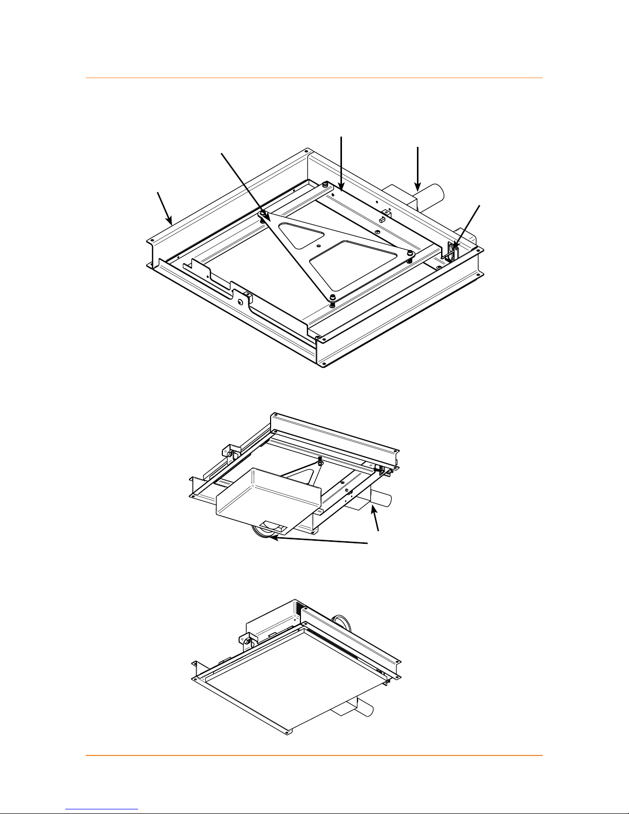
The Skyhook Projector Mount must be used for installation with the Flipper.
On Cleaning
To keep the unit looking new and clean a dust cover is supplied. If cleaning
is necessary use a soft cloth and mild detergent solution. Never use strong
solvents, such as thinners, benzene, or abrasive cleaners.

4 | LP Morgan Installation Instructions
LP Morgan Flipper Manual
Unpacking the Flipper
Supplied parts (accessories list)
Control Unit
12V Power Supply
Undercoated timber panel
(affixed)
Aluminium Ceiling Trim
Powdercoated steel frame and
pivot assembly
Wall Switch and
Architrave Mount
Cardboard Dust cover
LP Morgan Skyhook Projector
Mount System (including
mounting bolts and spacers)
When unpacking the Flipper, please handle all parts with care.
Do not destroy the folded inner box when unpacking,
as it is the dust cover for this unit!

LP Morgan Installation Instructions | 5
LP Morgan Flipper Manual
Part names
Flipper Frame
Skyhook Plate
Pivot Frame
Motor
Limit Switches
FRONT
Orientation - In use
Orientation - Not in use
Note motor position and
projector orientation

6 | LP Morgan Installation Instructions
LP Morgan Flipper Manual
Dimensions
D
E
C
FG
Back View, Closed Position
Top View, Closed Position
A
B
C
Front

LP Morgan Installation Instructions | 7
LP Morgan Flipper Manual
D
H
A
IJ
K
Side View, Closed Position
Front
Dimensions
Dimension Name Std Flipper Lrg Flipper
A Overall Length 575 675
B Frame Width 515 625
C Overall Width 670 770
D Closed Height 84 84
E Face Panel Width 450 550
F LHS Panel Offset 40 40
G RHS Panel Offset 180 180
H Face Panel Length 500 600
I Rear Offset 37.5 37.5
J Front Offset 37.5 37.5
K Operating Height 350 400

8 | LP Morgan Installation Instructions
LP Morgan Flipper Manual
Mechanical Installation
The Flipper may be installed through its own hole if required.
The first crucial step, like any projector installation, is to determine where
to put the Flipper in the ceiling. The Flipper should be installed so that the
projector lens is centered horizontally to the screen, and the distance from the
screen depends on the projector’s throw distance.
Work out the maximum and minimum throw distances for the projector and
place the Flipper somewhere in between. It is better for the projector to be
closer to the screen, but don’t place it at an extreme—leave yourself some
room to adjust the zoom in either direction.
Note:
When aligning the Flipper make sure that the projector lens is centred on the
screen, which is not necessarily the projector centre.
Screen
Screen centre
Lens centre
Projector centre
Throw Distance

LP Morgan Installation Instructions | 9
LP Morgan Flipper Manual
The Flipper was designed by an installer, with the installer in mind. The face
panel that is supplied is 18mm undercoated MDF, and is easily removed via
six screws.
We recommend that you remove and paint this panel before fixing the Flipper
in the ceiling.
In the case of a non-plasterboard ceiling, you may choose to fabricate your own
ceiling panel (eg. from the same timber/material as the ceiling itself) to match.
The Ceiling trim we supply will leave a 2mm clearance on all sides of this
face panel.
If you choose not to use this ceiling trim, you should be aware that you will
need to allow more clearance at the front and back of the panel, because the
trajectory traced by the ceiling panel is actually wider than the ceiling trim.
For a Standard Flipper Length Width
Face Panel 500 450
Cutout required, if NOT using the supplied trim 508 454
Cutout required, if using the supplied trim 528 478
For a Large Flipper Length Width
Face Panel 600 550
Cutout required, if NOT using the supplied trim 608 554
Cutout required, if using the supplied trim 628 578
Ceiling opening

10 | LP Morgan Installation Instructions
LP Morgan Flipper Manual
Ceiling Space
The following diagrams show the position of the ceiling cutout in relation to the
Flipper frame, the space required above the ceiling, and the mounting hole
positions.
The Flipper has been designed to be compatible with just about any installation
situation. You should be able to adapt the Flipper to suit your specific installation
requirements.
The Flipper frame is designed to sit 12.5mm above the ceiling—that is, it virtually
rests on the plaster!
Where possible, install the Flipper in such a way that you can micro adjust
the height so you can get it exactly flush with the ceiling, eg. suspended from
threaded rod.
A
N
FRONT
C
O
P
LM
M
K
Table of contents
Other LP Morgan Projector manuals


