LRP electronic SPHERE COMPETITION BRUSHLESS + BRUSHED User manual

!
A B C +
-
C
B
A
+
-
A B C +
-
•
IMPORTANT:
Never leave your RC model unsupervised when the
battery is plugged in. If a defect occurs, it could set fi re to the
model or the surroundings.
•
Never wrap your speed-control in plastic fi lm or metal foil. In fact,
make sure it gets enough fresh air.
•
Avoid soldering longer then 5sec per soldering joint when repla-
cing the power wires to prevent possible damage to the speed-
control due to overheating of the components!
IMPORTANT: Pay close attention
to the following points, as they
will
destroy
the speed-control and
destroy the speed-control and destroy
void your warranty:
•
Never allow the speed-control or other electronic components to
come in contact with water. Do not operate the speed-control
in the rain. If you ever have to operate in the rain, protect your
speed-control properly to avoid that water reaches the speedo.
•
If the speed-control is connected to the motor, never run the motor
directly with a separate battery or run-in device.
•
Never connect the speed-control incorrectly or with reversed
polarity.
•
All wires and connections have to be well insulated. Short-circuits
will destroy the speed-control. Pay special attention to the recei-
ver- and switch wires.
•
Never change the polarity of the receiver connector.
•
Never open the speed control and never solder on the PCB (except
on external solder-tabs).
WARNING NOTES
SPECIFICATIONS
•
Mount
the speed
o
using the supplied thick/black doubled-sided tape
.
D
o not use the clear Scotch 468MP tape!
• Position the speed-control where it is protected in the event of a crash.
• Install the speed-control so that you have easy access to the connector and buttons.
•
Make sure there is enough clearance (about 3cm) between the speed-control, power-
wires
, antenna and
receiver
.
Avoid any
direct contact between power components, the receiver or the antenna. This can cause
interference. If
interference occurs, position the components at a difference place in the model.
• The aerial should be run vertically up and away from the receiver. Avoid contact with any parts made of
carbon fi bre
or metal. If the aerial is too long, don’t coil up the excess length. It is better to cut it down to a
length of about 35
cm. See also the instructions supplied with your radio control system.
• Make sure there are enough cooling slits in the body. This will increase the performance and life of all the
electronic
components.
INSTALLATION TIPS
CONNECTIONS
RECEIVER CONNECTING WIRE:
This
LRP
speed-control is equipped with an LRP Multicon
receiver
wire. As supplied, it will easily fi t in all ordinary receivers.
H
ALL SENSOR WIRE
:
This bi-directional multipole wire (which comes with the motor and NOT the speed-control!) connects the speed-cont-
rol and the motor. Do not alter or modify this cable! There are replaceable
/optional
rol and the motor. Do not alter or modify this cable! There are replaceable/optionalrol and the motor. Do not alter or modify this cable! There are replaceable
hall sensor wires available:
•
#81910 (20cm)
•
#81920 (10cm)
POWER WIRES
:
For maximum performance,
13AWG power wires
w
ithout any connectors
are used
.
The unique splitted solder-tabs
allow easy and convenient replacement of the power wires.
Nevertheless some soldering skills are required
. A
void
soldering longer then 5sec per soldering joint
to prevent possible damage to the speed-control due to overheating of
the components!
There is a
full 13awg
replacement power wire set available:
#82505
CONNECTION
* Transistors rating at 25°C junction temperature. Specifi cations subject to change without notice.
**@ 6cells (7,2V)
Dear Customer,
Thank you for your trust in this LRP product. By purchasing a SPHERE COMPETITION speed-
control,
you have chosen
one of the most advanced speed-controls of today, which is full of new design
features such as:
• Automatic Brushless / Brushed Adaptation
• Forward/Brake Racing Speed-Control
•
IceDrive Design
•
AutoCell System - NiMH/Li
Po A
d
aptation
•
Super-Low Motorlimit
• Se
nsored Brushless Technology
• Blue metalised case
and bl
ue LED
•
13AWG power-w
ires +
e
xternal solder tabs
•
Multi-Protection System
•
Intuitive
QC-style programming
•
Ad
vanced
D
igital
with
4 adj.
M
odes (
AutoCell System, ADPC™, Initial-Brake, Automatic-Brake)
Please read and understand these instructions completely before you use this product!
With operating this product
, you accept the LRP warranty terms
.
USER GUIDE
BRUSHED MOTOR:
•
Bl
ue
/
Yellow power-w
/Yellow power-w/
ire
Speedo
MOT.A
/MOT.B
MOT.A/MOT.B MOT.A
to
„Minus“
on
the mo
tor
.
•
Orange
power-wire
Speedo
MOT.
C
to
„Plus“
on the motor
.
BRUSHLESS MOTOR:
•
Blue power-wire
Speedo
MOT.A
to mo
tor
„A“
•
Yellow power-wire
Speedo
MOT.
B
to mo
tor
„
B
“
•
Oran
ge power-wire
Speedo
MOT.
C
to mo
tor
„
C
“
•
Connect the hall sensor cable to the speed-control and the motor.
HEATSINK:
We recommend using the supplied heatsink in order to
achieve best performance even under extreme circumstances. Clean
the heatsink and stickerplate before you attach the
clear/thin
Scotch
468MP
thermal tape to
guarantee
perfe
ct
heat
dissipation
.
Caution
:
U
se
ONLY
the supplied clea
r/thin
Scot
ch 468MP
thermal tape
to attach the heatsink
!
Do not us standard double
sided tape
!
LRP electronic GmbH
Wilhelm-Enssle-Str. 132-134, 73630 Remshalden, Germany
Tel.: int+49-7181-4098-0, Fax: int+49-7181-4098-30
INF
O
@
LRP-ELECTRONIC.DE
WWW.LRP-ELECTRONIC.DE
ORDER NO,:
80700
BRUSHLESS + BRUSHED
OVER 3.5T (BRUSHLESS)
OVER 5T (BRUSHED)
Brushless AND Brushed
yes
(automatic adaptation)
Typ.Volt.Drop (Brushed)* @20A
0.013V
Forward/Brake
yes
(racing style)
Rec. Motor Limit (Brushed)**
>5 turns
Case Size
33.1x37.6x14.9
Rated Current (Brushed)*
400A
Weight (excl. wires)
24.5g
B.E.C.
5.5V
/
3.0A
Voltage Input
4-7 cells (4.8-8.4V)
High Frequency
yes
Typ.Volt.Drop
(Brushless)
* @20A
0.018V / phase
Sensored Brushless System
yes
Rated Current (Brushless)*
400A / phase
Multi-Protection-System
yes
Rec. Motor Limit (Brushless)**
>3.5 turns
Power Wires
13awg
4 adj. Modes (NiMH/LiPo, ADPC™ Power Profi les, Initial Brake, Automatic Brake)
yes
Because of the physical principles of brushless technology, the speed-
controls do get a little hotter then brushed systems. Therefore it is re-
quired to let the speed-control cool down completely after every run.
When running in extreme conditions (high ambient temperature, low-
turn motors, high gear ratios, etc.) we recommend using LRP‘s brush-
less cooling set #82500, which includes
a pre-wire
d and perfectly sized
fan and a spare power-capacitor.
On/Off
On/Off
Swit
ch
ch
MOT.C (Orange)
Receiver
Receiver
wire
wire
The S
PHERE COMPETITION
is supplied with
1
3AWG power-wires without
connectors.
B
e very careful with the cor-
rect wire sequence
/colors since an in
rect wire sequence/colors since an inrect wire sequence
correct
connection
s
may
damage the speed-control
! Avoid
creating
solder
bridges
on the
solder-tabs and isolate
all
connections car
ef
ully.
C
aution
:
A
void soldering longer then 5sec per soldering joint when replacing the
power wires
on spe
ed-control and
motor
to prevent possible damage due to overheating of the components!
•
Connect the speed-control to the receiver (position: channel 2)
•
Doublec
heck all connections before connecting the speed-control to a battery
.
C
AUTION
:
If
battery is connected with reversed polarity it will destroy your speed-control!
•
Red power-wire
Speedo BA
T+ to battery „Plus“
•
Black
power-wire
Speedo BAT- to battery „Minus“
• The speed-control is now ready
to be set-up (see back side)
.
SUPPRESSION
ONLY FOR BRUSHED MOTORS!
Motors with no capa-
citors or not enough capacitors may interfere with the
speed-control. To avoid this, solder the supplied capaci-
tors to your motor (see picture).
orange
orange
orange
blue
yellow
blue
yellow
yellow
orange
Hall Sensor Wire
together to minus
yellow
yellow
RA00173
Hall Sensor
Hall Sensor
Connector
Power Capacitor
BAT + (Red)
MOT.B (Yellow)
BAT
-
(Black)
MOT.A (Blue)
Mo
unt the power-capacitor in a positi-
on where it is protec
ted in the event of
a crash. T
he best place is right below
the solder tabs
and secure it with dou-
blesided tape.

In setup mode the
SPHERE COMPETITION
stores every step when you press the SET button. All the settings will be
stored in the speed-controls memory even if the speed-control will be
disconnected from the battery.
RADIO / SPEED-CONTROL SET-UP
Throttle travel
High ATV, EPA
High ATV, EPA
maximum
Brake travel
Low ATV, EPA, ATL
maximum
Throttle exponential
EXP, EXPO
start with 0
Neutral trim
SUB Trim
centre
Serve reverse
Throttle reverse
any setting, don‘t change after set-up procedure!
TRANSMITTER SETTINGS
Setup the following basic functions on your transmitter (if available):
If your transmitter doesn‘t offer any of above functions, it‘s already in „basic setup“ mode.
• En
sure that the speed-control is not connected to the drive battery, and is switched off.
•
Remove motor pinion, or ensure that the wheel
s of the model are free to rotate.
•
Switch the transmitter on and set the transmitter throttle stick to neutral..
•
Connect
. the speed
-control to the battery, and
switch the unit on.
•
Hold the SET button p
ressed for at least 3sec using the supplied plastic screwdriver.
you entere
d setup mode and
SET LED fl ashe
s
blue
(it
will fl ash until the
setup is comp
leted).
•
Leave radio in neutral
and press the SET button once.
neutral setting is stored , MODE L
and press the SET button once.
neutral setting is stored , MODE L
and press the SET button once.
ED fl ashes yellow an
and press the SET button once.
ED fl ashes yellow an
and press the SET button once.
d the motor beeps.
•
Hold fu
ll throttle on radio
and press the SET button once.
full-throttle setting is stored,
and press the SET button once.
full-throttle setting is stored,
and press the SET button once.
MODE LED fl ashes red.
and press the SET button once.
MODE LED fl ashes red.
and press the SET button once.
•
Hold fu
ll brake on radio
and press the SET button once.
bra
ke setting is stored, LED‘s glow red (MODE) and blue (SET)
and press the SET button once.
ke setting is stored, LED‘s glow red (MODE) and blue (SET)
and press the SET button once.
.
•
This completes the setup pro
cedure and your
SPHERE COMPETITION
is ready to us
e.
•
If you make a mistake during the setup proce
dure, don‘t worry: disconnect the battery for about 10sec and
start
ag
ain from the fi rst step.
•
At the end of each run
switch of the car
, and only then switch off the transmitter.
•
At the start of each run switch on the transmitter fi rst, then
switch on the car.
•
F
or storage of the car, disconne
ct the drive battery at any time!
FUNCTION
STATUS
MODE LED
SET LED
Neutral (automatic brake inactive)
--
off
blue
Neutral (automatic brake active)
--
red
off
Forward
partial throttle
partial throttle
yellow
yellow
off
Forward
full throttle
yellow
yellow
blue
Brake
partial brake
partial brake
red
off
Brake
full brake
red
blue
CHECKING THE FUNCTIONS:
Check
the
LED‘s when moving your throttle stick and you will see if everything is setup correctly.
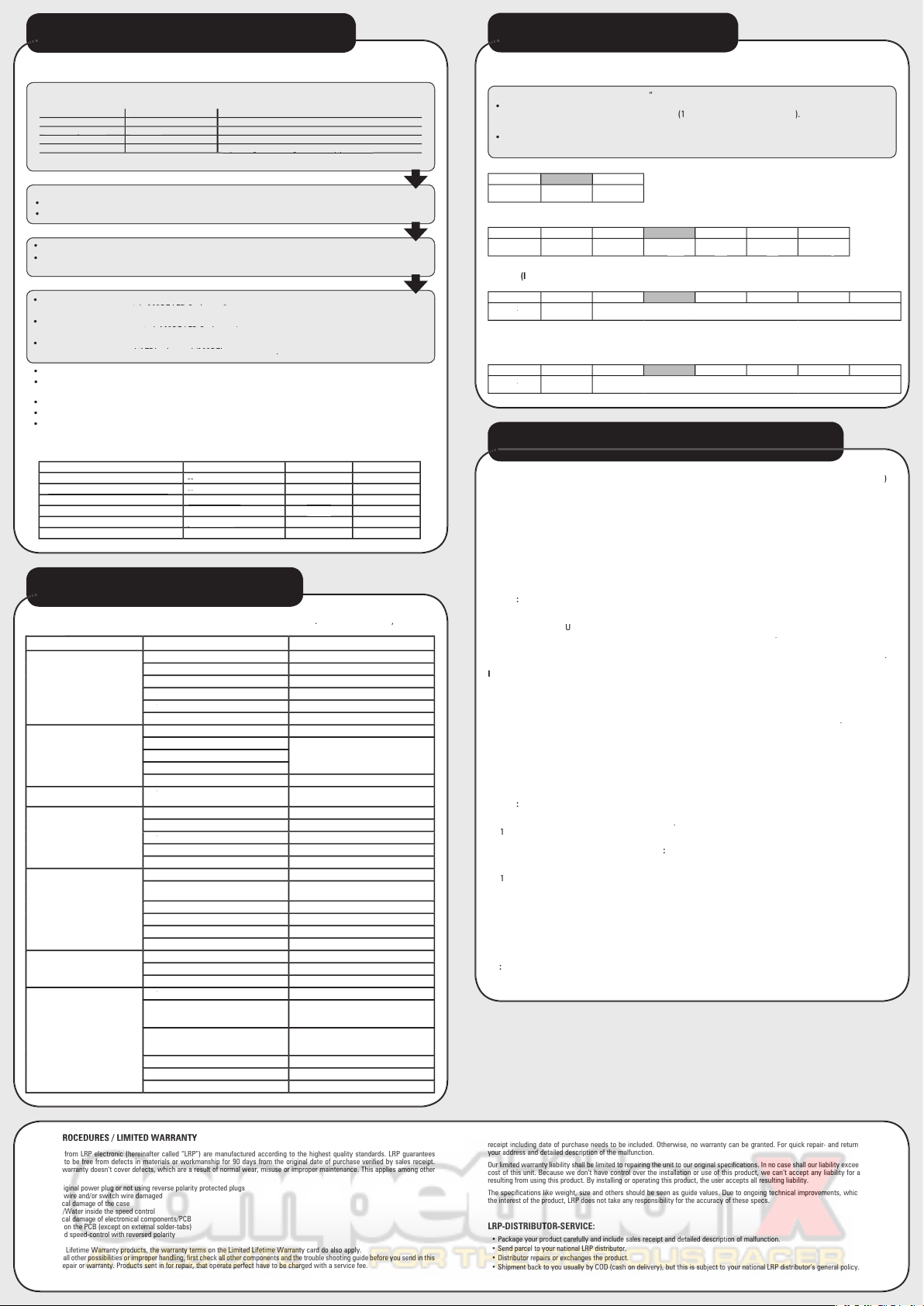
REPAIR PROCEDURES / LIMITED WARRANTY
All products from LRP electronic (hereinafter called “LRP”) are manufactured according to the highest quality standards. LRP guarantees
this product to be free from defects in materials or workmanship for 90 days from the original date of purchase verifi ed by sales receipt.
This limited warranty doesn’t cover defects, which are a result of normal wear, misuse or improper maintenance. This applies among other
things on:
•
Cut off original power plug or not using reverse polarity protected plugs
•
Receiver wire and/or switch wire damaged
•
Mechanical damage of the case
•
Humidity/Water inside the speed control
•
Mechanical damage of electronical components/PCB
•
Soldered on the PCB (except on external solder-tabs)
•
Connected speed-control with reversed polarity
With Limited Lifetime Warranty products, the warranty terms on the Limited Lifetime Warranty card do also apply.
To eliminate all other possibilities or improper handling, fi rst check all other components and the trouble shooting guide before you send in this
product for repair or warranty. Products sent in for repair, that operate perfect have to be charged with a service fee.
SYMPTOM
CAUSE
REMEDY
Servo is working, no motor function.
Speed-control plugged in incorrectly
Plug speed-control in Ch 2
Overload protection activated
Allow speed-control to cool down
Wiring problem
Check wires and plugs
Motor defective
Replace motor
BM
- Motor brushes stuck
BM - Motor brushes stuckBM
Check that brushes are moving freely
Speed-control defective
Send in product for repair
No servo and no motor function.
Speed-control plugged in incorrectly
Plug speed-control in with correct polarity
Crystal defective
Replace components one by one.
Receiver defective
Transmitter defective
Speed-control defective
Send in product for repair
Motor runs in reverse when accelera-
ting forward on the transmitter.
BM
- Motor connected incorrectly
BM - Motor connected incorrectlyBM
Connect motor correctly
Insuffi cient performance.
E.g. poor brake power, topspeed or
acceleration..
Motor pinion too big or gear ratio too long.
Use smaller motor pinion/shorter gear ratio
Transmitter settings changed after set-up
Repeat set-up procedure
BM
- Motor worn out
BM - Motor worn outBM
Maintain motor
Motor defective
Replace motor
Speed-control defective.
Send in product for repair
Speed-control overheats or switches
off frequently.
No heatsink installed
Install heatsink
Motor stronger than motorlimit or input voltage
too high
Use only motors and batteries which are within
the specifi cations of the speed-control
Motor pinion too big or gear ratio too long.
Use smaller motor pinion/shorter gear ratio
Drive train or bearing problems.
Check or replace components.
Model used too often without cool-down periods
Let speed-control cool down after every run
Extreme conditions
Use additional cooling fan
Motor never stops, runs at constant
slow speed
Transmitter settings changed after set-up
Repeat set-up procedure
Humidity/water in speed-control
Immediately unplug and dry speed-control
Speed-control defective
Send in product for repair
Radio interference
BM
- Motor suppressors not suffi cient
BM - Motor suppressors not suffi cientBM
Solder capacitors to motor
Receiver or antenna too close to power wires,
motor, battery or speed-control.
Receiver aerial too short or coiled up
See „Installation Tips“ and „Installation“
Receiver defective, too sensitive;
Transmitter defective, transmitter output power
too low, servo problem
Replace components one by one
Only use original manufacturers crystals
Poor battery connection
Check plugs and connecting wires
Transmitter batteries empty
Replace / recharge transmitter batteries
Transmitter antenna too short
Pull out antenna to full length
E
x
lanation
:
If no remark, cause can be either
with
brushles
s or brushed m
otor
.
If „
B
M
“
is indi
cated
,
cause
on
ly
relating to
brushed motor.
TROUBLESHOOTING GUIDE
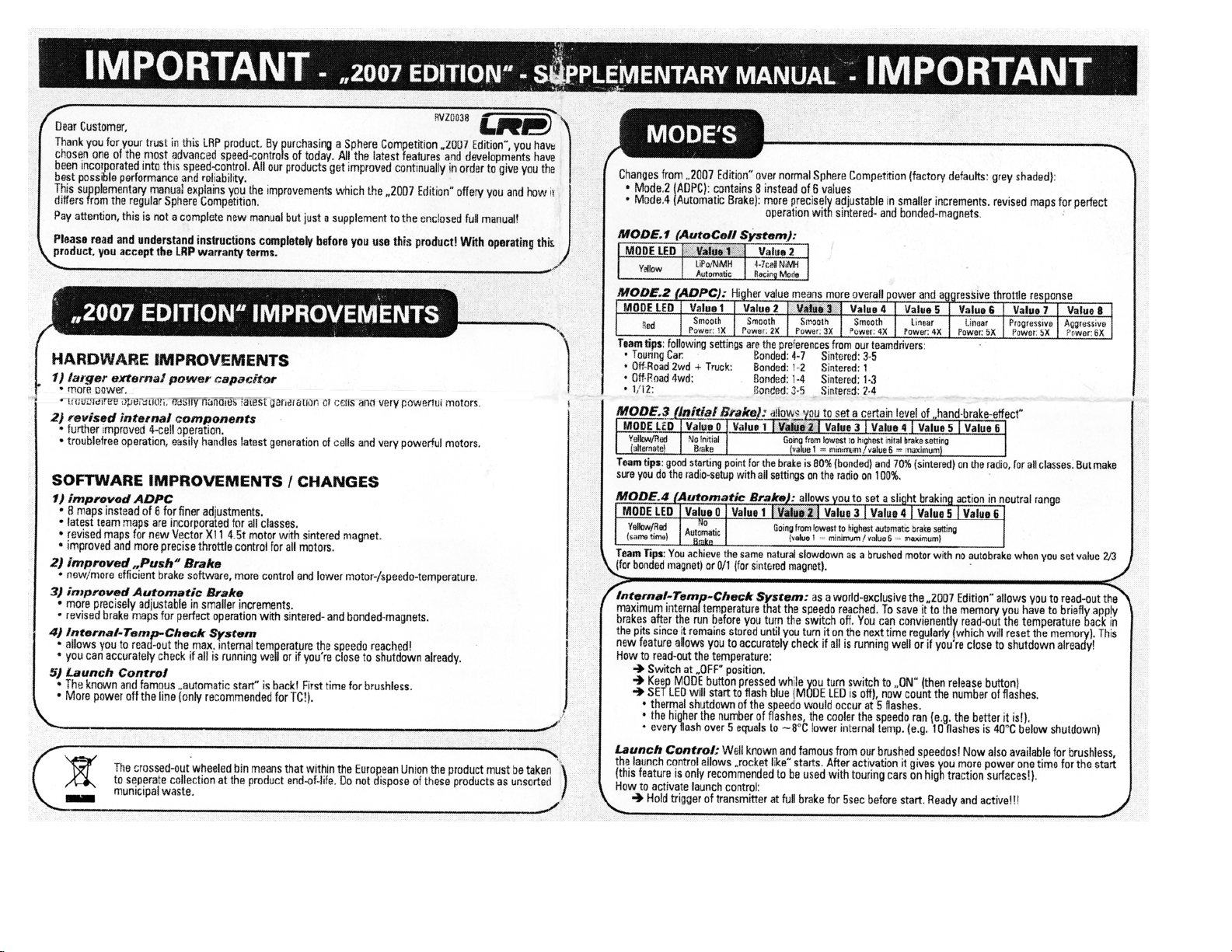
All modes are available for brushless and brushed motors (
speedo adapts
automatically).
The SPHERE COMPETITION features 4 modes which enable you to adjust it to YOUR special requirements.
MODE.1 (AutoCell System)
:
see
below
for explanation
s.
MODE 2 (ADPC™+ DEMS drive-/punch-control)
:
see
below
for explanation
s.
MODE.3
(
I
nitial Brake):
allows you to set a certain level of “hand-brake effect“, i.e. you can vary the minmum brake
effect when you apply the brake.
MODE.4 (Automatic Brake):
allows you to set a slight braking action which is applied in the neutral range. This
enables you to simulate the feel of a brushed motor and also hold the throttle on longer when entering a turn.
Tip:
Value 2 with brushless has identical natural slowdown as brushed without automatic brake.
MODE PROGRAMMING
MODE LED
Value 0
Value 1
Value 2
Value 3
Value
4
Value
5
Value 6
Yellow
/Red
Yellow/Red Yellow
(same time)
No
Automatic
Brake
Going from lowest to highest automatic brake setting
(value 1 = minimum / value 6 = maximum)
MODE LED
Value 0
Value 1
Value 2
Value 3
Value
4
Value
5
Value 6
Yellow
/Red
Yellow/Red Yellow
(alternate)
No
Initial
Brake
Going from lowest to highest inital
brake setting
(value 1 = minimum / value 6 = maximum)
MODE LED
Value 1
Value 2
Value 3
Value
4
Value
5
Value 6
Red
S
mooth, low
traction
Very Linear
Linear,
incr
ea-
sed
punch
Aggressive
map
Very aggressive
map
Super aggressi-
ve ma
p
MODE LED
Value 1
Value 2
Yellow
LiPo/NiMH
Automatic
4-7cell NiMH
Racing Mode
•
How to get into „programming the modes
“
Press
MODE button for 3+sec.
•
How to check the stored values
C
ount the number of fl ashe
s of the blue SET-LED
(
1
x
= value 1, 2
x
= value 2, etc.
)
.
• How to change the value
Press SET button to increase v
alue by one step.
•
How to get to the next Mode
P
ress M
ODE button
o
nce.
•
Table of settings
,
values and modes: see below (grey-shaded values show
„works default set
tings).
WORKS DEFAULT SETTINGS
:
A
ll L
RP speed-controls
come
factory-adjusted
(de
faults are grey-shaded
above
)
. If
you loose track of the modes, you can res
tore
the
works default settings
.
With the transmitter switched on, hold
the SET button pressed while you switch on the speed-control. This
simple
action returns the unit to the LRP works
default settings.
CHANGING MODE SETTINGS WITHOUT THE TRANSMITTER
:
At race events you usually do not have access to
your transmitter
, but never mind since you can
simply
disconnect the receiver lead from the receiver and
c
hange the
MODE settings as described in this chapter.
AUTOMATIC BRUSHLESS / BRUSHED ADAPTATION
:
The LRP exclusive Automatic Brushless/Brushed Adapt
at
ion
detects the connected motor type
during
turn-on
/
initialisation
and adjusts the correct brushless or brushed
operation
automatically
.
No
adjustment
s
required by yourself, apart from the correct connection of each motor type (don‘t
forget the hall-sensor-wire for brushless!).
Caution
:
Keep in mind, when swopping between brushless and brushed motors, that the choosen mode values will
be identical!
FORWARD / BRAKE
:
U
ncompromising and outstanding performance
for
top level competition
was the target!
There-
fore the
LRP engineering team
develop
ed
a pure forward/brake
co
mpetition
speed
-
control without reverse function.
P
OWER CAPACITOR
:
Never disconnect the power-capacitor!
It offers
increased
punch
an
d
additional protection
.
I
ceDrive DESIGN
:
LRP’s secret IceDrive Design results in lower speedo temperature under all racing conditions
and
for b
oth brushless + brushed
. Sorry, no further details to be disclosed. Simply a step ahead of the competition!
AutoCell SYSTEM
:
Ready
for th
e next battery technology – LiPo batteries! LRP’s exclusive and smart AutoCell
System ensures that LiPo batteries can be used safely without
accidentially
deep-discharging
of
the cells.
T
he motor
function will be shut-off and the SET LED will fl ash
if
the system recognises very low battery voltage
.
T
ip
:
We recommend using value 2 for 4-7 cells NiMH racing purposes, which disengages the LiPo protection.
SENSORED BRUSHLESS TECHNOLOGY
:
Advanced Digital allows the perfect knowledge of the brushless motor’s
magnet position. This
results in
perfect motor control at high and low RPM‘s, as well as perfect brake control.
ADPC™ BRUSHLESS - DRIVE-/PUNCH-CONTROL
:
an all new brushless technology which results in more power
and better driveability. Depending on the status of the car (start, acceleration and full speed) the software calculates
the perfect motor management. Higher value means more overall power and
aggressive response
.
Caution
:
Do not
advance
mechanical timing on the
motor
w
hen you
use
ADPC values 3 to 6
. L
eave the motor
timing on
minimum timing, which
e
q
uals to
2mm
on
sticker.
W
e
recommend the following settings for each class
.
•
1
/12: 2
-
3
•
Off-Road: 1 - 4
•
Touring Car: 3 - 5
•
Stock BL: 6
D.E.M.S. BRUSHED -
DRIVE-/PUNCH-CONTROL
:
the known and world‘s winning
D.E.M.S. Brushed
Quantum style
power programs have been implemented.
Higher value means more overall power and
aggressive response
, we
recommend the following settings for each class:
•
1
/12: 2
-
3
•
Off-Road: 1 - 4
•
Touring Car: 3 - 5
• 19/27
t
motors
: 6
MULTI-PROTECTION SYSTEM,
3
-way Protection
:
the perfect protection against short-circuits (motor), overload
and overheating. If your speed-control faces overload, the motor function will be shut-off for protection and the SET
LED will fl ash, although the steering function is maintained. Let the speed-control cool down for a few minutes. If you
experience frequent shutdowns, check for the following:
•
Correct gear ratio (refer to motor manual for gearing recommendations)
• ADPC setting too high (higher
val
ue will heat up motor a
nd
speed
-control excessively)
• Motor is too strong or motor is damaged.
T
ip
:
Always use the
supplied heatsink, if you still experience shutdown
issues
you should consider obtaining the
optional LRP brushless cooling set (#82500).
MODE FEATURES & EXPLANATIONS
By sending in this product, you assign LRP to repair the product, if it is no warranty or Limited Lifetime Warranty case. The original sales
receipt including date of purchase needs to be included. Otherwise, no warranty can be granted. For quick repair- and return service, add
your address and detailed description of the malfunction.
Our limited warranty liability shall be limited to repairing the unit to our original specifi cations. In no case shall our liability exceed the original
cost of this unit. Because we don’t have control over the installation or use of this product, we can‘t accept any liability for any damages
resulting from using this product. By installing or operating this product, the user accepts all resulting liability.
The specifi cations like weight, size and others should be seen as guide values. Due to ongoing technical improvements, which are done in
the interest of the product, LRP does not take any responsibility for the accuracy of these specs.
LRP-DISTRIBUTOR-SERVICE:
•
Package your product carefully and include sales receipt and detailed description of malfunction.
•
Send parcel to your national LRP distributor.
•
Distributor repairs or exchanges the product.
•
Shipment back to you usually by COD (cash on delivery), but this is subject to your national LRP distributor‘s general policy.

This manual suits for next models
1
Other LRP electronic Motorized Toy Car manuals
Popular Motorized Toy Car manuals by other brands

Famosa
Famosa Feber Adventurer Tandem Car quick start guide

Tamco
Tamco Ranger Instruction manual & parts catalogue

Rollplay
Rollplay FLEX KART XL PEDAL Owner's manual and assembly instructions

Nerf
Nerf TERRASCOUT manual

Tamiya
Tamiya TXT-1 Assembly instructions

HPI Racing
HPI Racing Hellfire instruction manual