LRS Narrow Planet NPL-008 User manual

About the kit
This kit is comprised of a 3D printed plastic body shell, a fret of
etched nickel silver detail parts, a 3D printed brass chassis,
wheels, gears and a motor. Minimal folding of the nickel silver
parts is required and they can all be glued in place. A small
amount of soldering is necessary to complete the electrical
connections. Full assembly instructions are given below.
Due to the nature of the 3D printing process, some support
material may still be present on bottom-facing edges of the body
shell, particularly underneath the buffers. The plastic used has
similar properties to the ABS commonly used in injection-moulded
kits and may be easily cleaned up with a sharp knife and fine
emery boards.
Please note this is a scale model for adult collectors, and not
intended for children under 14 years of age.
Detail Parts • NPL-008 v3.0
Carefully remove each part from the fret as required using a
sharp knife on a cutting mat or similar hard surface, and clean up
the tags.
Initial preparation
Carefully remove the sprue containing the filler caps from inside
the body print and put safely to one side. Use a small file to
remove any remaining sprue from the body.
Make sure the chassis fits in the body properly as it will be difficult
to alter after assembly. It should be a tight push fit with the
locating pins on the body fitting between the matching pins on the
chassis. If the two parts don’t fit properly then file either the
chassis or body slightly to ensure that they do.
Take the four spacers (4) off the etch and glue or solder them
together in pairs to give yourself two 0.5mm thick parts.
Assembling the Chassis
The layshaft and axles are both notionally 1.5mm in diameter and
the bearing holes have been reamed out to 1.55mm so should be
a smooth fit, but check for burrs on the layshaft ends before fitting
to avoid damaging the bearing surfaces and to ensure that the
brass worms are a sliding fit.
1 • Start by attaching the large pulley to one end of the layshaft
and fixing with Loctite 243 (medium strength threadlocker),
making sure the pulley is square to the shaft. If you need to ream
out the hole do so carefully to make the fit as tight as possible, as
that will help ensure the pulley sits at 90 degrees to the shaft and
doesn’t wobble. File any protruding shaft flat to the face of the
pulley as there is minimal clearance within the body shell.
2 • Slide the layshaft into the chassis from the end with the motor
mount. With the pulley pushed flush against the chassis, trim off
any layshaft that protrudes from the other end of the chassis and
file the end flush to the chassis, then remove the layshaft.
3 • Place the two brass worms into the chassis and then slide the
layshaft back into the chassis through both worms. Do not push
the pulley right up to the chassis, but instead use one of the
0.5mm spacers to keep a gap between the pulley and the chassis.
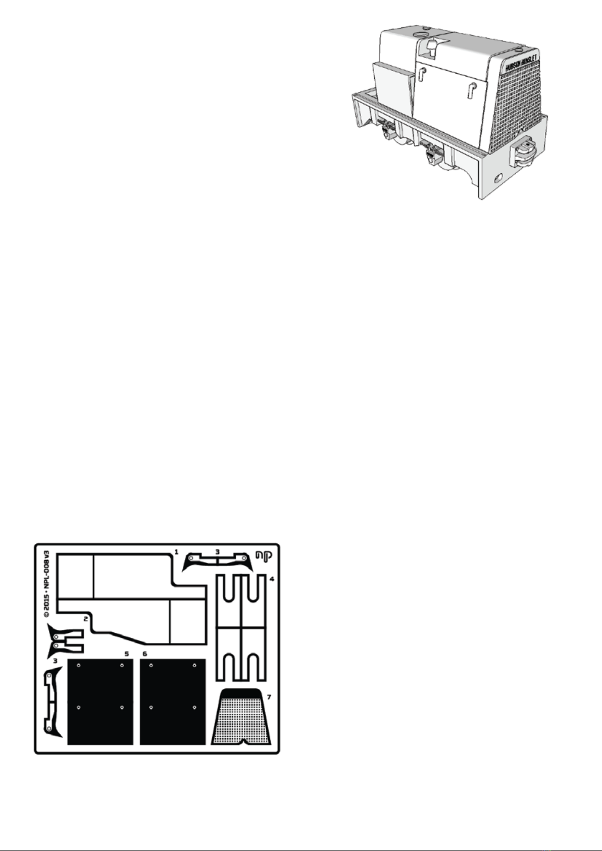
5. Solid side panels x 2
6. Side panels with grille x 2
7. Front grille
1. Large rear panel
2. Small rear panel
3. Brake shoes x 6
4. Assembly spacers x 4
np
NPL-008
Hudson-Hunslet
24hp light diesel
Thank you for purchasing this Narrow Planet kit, we hope you enjoy building and operating it.
Please read through the instructions thoroughly before beginning assembly.
Prototype Info
Introduced in the late 1950s, the
24hp light diesel locomotive was an
upgraded version of the company’s
original 21hp model and the smallest
in the range. This model, based on
Hunslet’s General Arrangement
Drawing 48937 of April 1961, rep-
resents the basic cabless version.
Many were, however, fitted with
varying designs of cab, and other
equipment, depending upon
intended use.
Preserved examples include
LCWW18, part of the Moseley
Railway Trust collection, and
"Creepy" of the Leighton Buzzard
Railway.
Tools required: Sharp craft knife or scalpel
Razor saw
Tweezers
Flat nosed pliers
Bending bars or engineer's square
Emery paper or boards
Small files
Dressmaker's pins or similar
Reamer (suitable for 0.8mm to 2mm)
1mm drill
Loctite 243
Superglue
Soldering iron and solder (solder
paste is recommended)
4 • Both worms need to be secured to the layshaft flush against
the inside ends of the chassis. In turn, slide each worm as far to the
end of the chassis as it will go. Using a pin add a small amount of
Loctite 243 to the layshaft against the inner end of the worm.
Move the worm along the shaft to pickup the loctite 243 and then
back so it rests against the end of the chassis all the while making
sure to keep the spacer in place so that the pulley is not touching
the end of the chassis. Leave for five minutes for the Loctite 243 to
fully grip and then remove the spacer and check that the shaft
turns freely.
5 • The next job is to prepare the two gears that will fit on to the
axles. We suggest doing this as follows. Gently ream out the gear
until you can just force the brass tubing in; it should be a very tight
fit but if it is at all loose then a small amount of superglue is
advised. With the end of the tube flush to one side of the gear, use a
razor saw to cut the tube leaving around 0.5mm protruding from the
other side. Use a pair of pliers to squeeze the tube to slightly distort it
(this helps the tube grip the axle later) before filing it flush against the
face of the gear. Repeat for the other gear.
6 • Each wheelset is then assembled in the same way. Start by
placing the gear into position with the slightly deformed tube on
the left and then force the axle (to aid assembly the insulated
wheel has already been removed) through from the right hand
side of the chassis. Use one of the spacers to ensure a 0.5mm gap
between the back of the wheel and the side of the chassis and try to
ensure the gear stays in the centre of the space rather than being
forced up against one side. Now gently refit the insulated wheel
making sure it is square to the axle, which is easiest to achieve if you
push on the insulating washer rather than the wheel itself. Use the
spacers to again ensure that that there is a 0.5mm gap between
both wheels and the chassis. Repeat with the other wheelset.
7 • At this point the chassis will not fit in the body as the ends of
the axles get in the way. You need to file the axles back until they
are flush with the face of the wheel. Do this before fitting the
motor to avoid the risk of letting any filings get inside it.
8 • Now superglue the motor onto the motor mount so that the
main face of the motor is level with the outer end of the mount.
Carefully ream out the hole in the small pulley until it will slide onto
the drive shaft – do not force it. Place a small amount of Loctite
243 inside the pulley and slide it on to the motor, and make sure it
is aligned vertically above the main pulley. Leave for a few minutes
for the Loctite 243 to take hold. Now you can fit the drive belt.
9 • At this point you can test that everything works before fitting
the pickups. One approach is to use Blu-tac to hold the chassis
upside down and then temporarily connect it to a standard 12V
power supply via the large resistor (not the tiny surface mount
one). Hopefully everything should run nicely but you might have to
help it on it’s way to start with (push the pulley round whilst under
power) which helps get over any initial tight spots. Once it is
running let it run for an hour in each direction to make sure it is all
nicely run in.
Fitting the pickups
Now that the chassis works the final step is to make sure it can collect
power from the track. This is the most fiddly step so take your time.
There isn’t a lot of space inside the body, especially once the area
above the motor has been filed with weight, so where possible trim
the motor wires as short as you sensibly can, otherwise they may
make it difficult to fit everything inside the body. Read through the
rest of this section to work out where everything goes to help
determine how short the wires can be trimmed.
1 • First you need to solder the red wire directly to the chassis. The
best place to do this is the vertical surface of the motor mount, in
the middle of the chassis above the layshaft, on the side of the
non-insulated wheels. One suggestion is to use a syringe to apply
a small amount of solder paste in the right place, which then helps
to grip the bare end of the wire. A quick dab with a hot soldering
iron and the joint is formed. If any solder runs on to the outside
edges of the chassis file it back, otherwise the chassis might not fit
within the body.
2 • Use a file to make a gap across the middle of the small piece of
PCB. Now solder the resistor to the PCB so that the ends are on
either side of the gap. Solder paste can again be useful to help
hold the resistor in place. Now solder the pickup wire to one end of
the PCB; the wire naturally curves, make sure it curves upwards
away from the PCB when you solder it on.
3 • Feed the black wire down through the centre of the chassis on
the same side of the layshaft as the non-insulated wheels and
solder to near the resistor on the opposite side to the pickup strip.
Now gently position the PCB so that it lays flat, resistor down-
wards, on the bottom of the chassis and the pickups touch the top
of the wheels. Once you are happy with the positioning use a small
amout of superglue to fix it in place and trim the pickup wire to
length if necessary. You should now be able to place the chassis on
the track and see it move, although you may need to tweak the
pickups to get it to work reliably.
4 • The final step in assembling the chassis is to fit the brake shoes
(3). Remove each one from the etch and fold the end over. Once
folded they glue on to the protruding parts of the chassis at the
outer side of each wheel. Make sure that they don’t touch the
wheels as not only will this damage them but if they touch the
insulated wheels they will cause a short circuit. With everything
assembled the chassis should now slide into the body. It will be a
tight fit and the easiest way to remove it is to use a pair of pliers to
grip one of the axle mounts and gently pull.
Assembling the body
The printed body will have been cleaned before packing, but may
need a small amount of preparation before assembly. Check for
any rough surfaces and smooth these gently before starting to
assemble the body; you can easily smooth the surfaces by gently
rubbing with a coffee stirrer.
1 • There isn’t much space to add weight to the model, but as much
as possible of the body has been hollowed out so that Liquid
Gravity or similar can be added. With the body upside down you
can gently add weight into the space above where the motor fits,
allowing it to run back into the control panel area as well. Make
sure that the weight does not protrude too far down into the open
space otherwise the motor will not fit. Fix the weight in place using
superglue. Once dry, check that the chassis still fits properly. If not use
a file to remove any protruding bits. You can also add weight behind
the front buffer, again being careful not to obscure the opening in the
body through which the chassis fits. You can probably also squeeze a
tiny amount of weight into the starter battery!
2 • There are four cab control handles to fit from the 0.45mm brass
wire. Two levers are made from straight pieces of wire. These are
fitted into the hole in the footwell and into the bottom hole on the
control panel. The top control panel hole takes a short piece of wire
with the protruding end bent up at 90 degrees. The final lever is
inserted into the floor and bends at almost 90 degrees just after
leaving the hole to run alongside the driver position. When fitting the
final lever make sure the wire does not protrude out the bottom of
the hole otherwise it will interfere with the chassis preventing the
model from working properly.
3 • Insert a small piece of 0.45mm brass wire through the hole in
each coupling block leaving a short pin protruding from the top. This
will allow other stock using Greenwich couplings (or compatible) to be
coupled to the locomotive.
4 • Two types of side panel are supplied - one solid (5) and one with a
small grille hole (6). Prototype locos seemed to be fitted with either.
To detail the panels, first tape a small thin piece of cardboard to the
outer surface of each piece just below the two holes. Cut the 0.33mm
nickel silver wire into four equal parts. Introduce a right angle bend
close to one end of a piece of wire and then slide the short end
through the hole and use another bit of tape to hold it in position.
Repeat for the other handle. Turn the panel over and apply a small
drop of superglue to each wire. One the glue has set trim the wire back
flush with the inside of the panel and then remove all the tape and card.
Trim the handles to a sensible length. Repeat for the other panel.
If using the panels with grille hole, to fix the mesh use a small piece of
tape to hold it to the inside of the panel, then carefully apply a small
bead of superglue along the edges of the mesh. Try to ensure it
doesn’t run onto the central part that will be visible from the outside.
Once dry remove the tape. You can now glue each panel onto the body
making sure to align the edges with the top part of the engine cover.
5 • Two different shaped rear panels are provided in the kit. The
slightly larger part (1) is intended to be fitted to cabless locomotives,
while the smaller part (2) works better when one of optional cab designs
(available separately) is to be fitted. Assuming you intend to fit the two
filler caps, start by drilling 1mm diameter holes through the rear etched
part using the two half etched holes as guides. Now gently fold the part
to shape so that it fits tightly over the body. If you find the fit isn’t quite
perfect you may need to file a small amount off the body.
Once you are happy with the fit use a small amount of superglue to
fix it in place. Once the glue has dried use a small file to round off the
top two folds to better match the curve of the front of the model. If
fitting the filler caps, drill 1mm holes into the plastic body through the
holes you previously drilled into the etched part. Check that the two
caps slide into the holes (the larger one should be towards the front
of the cab and sits flush to the body, while the smaller one should sit
slightly proud) and then glue into place.
6 • The supplied driver figure is initially a little too fat to fit in the seat.
You‘ll need to use a small file to gently remove some of his upper left
arm, right thigh, and feet until you can gently slide him into position.
7 • The final part to fit is the front grille (7). As it is impossible to paint
the area behind the grille after this has been fitted you may wish to
paint the model and grille separately and then glue the grille in place,
or at least paint the area behind the grille black before fitting it.
8 • The completed model can be painted using any of the common
modelling paints (acrylic or enamel). An initial layer of primer is
recommended to provide a consistent surface and colour as a basis
for final painting.
Acknowledgements
We would like to thank Rod Allcock, Jeff Bissonette, Neil Sayer and
the many members of the 009 Society and NGRM-Online who
provided feedback and support during the development of this kit.
About Narrow Planet
Narrow Planet was founded in 2010 and offers a custom etching
service for unique nameplates, works plates and number plates for
your model railway locos and stock. In any size or shape from 2mm:ft
to 16mm:ft scales. Many manufacturers’ styles are available, our full
range and ordering information can be found on our website. This kit
was designed by Mark A. Greenwood. If you have any queries about
the model or instructions please get in touch.
Contact Details
www.narrowplanet.co.uk
info@narrowplanet.co.uk
27 Terminus Avenue, Bexhill-on-Sea,
East Sussex, TN39 3LS
NPL-008 • first issue • October 2015

About the kit
This kit is comprised of a 3D printed plastic body shell, a fret of
etched nickel silver detail parts, a 3D printed brass chassis,
wheels, gears and a motor. Minimal folding of the nickel silver
parts is required and they can all be glued in place. A small
amount of soldering is necessary to complete the electrical
connections. Full assembly instructions are given below.
Due to the nature of the 3D printing process, some support
material may still be present on bottom-facing edges of the body
shell, particularly underneath the buffers. The plastic used has
similar properties to the ABS commonly used in injection-moulded
kits and may be easily cleaned up with a sharp knife and fine
emery boards.
Please note this is a scale model for adult collectors, and not
intended for children under 14 years of age.
Detail Parts • NPL-008 v3.0
Carefully remove each part from the fret as required using a
sharp knife on a cutting mat or similar hard surface, and clean up
the tags.
Initial preparation
Carefully remove the sprue containing the filler caps from inside
the body print and put safely to one side. Use a small file to
remove any remaining sprue from the body.
Make sure the chassis fits in the body properly as it will be difficult
to alter after assembly. It should be a tight push fit with the
locating pins on the body fitting between the matching pins on the
chassis. If the two parts don’t fit properly then file either the
chassis or body slightly to ensure that they do.
Take the four spacers (4) off the etch and glue or solder them
together in pairs to give yourself two 0.5mm thick parts.
Assembling the Chassis
The layshaft and axles are both notionally 1.5mm in diameter and
the bearing holes have been reamed out to 1.55mm so should be
a smooth fit, but check for burrs on the layshaft ends before fitting
to avoid damaging the bearing surfaces and to ensure that the
brass worms are a sliding fit.
1 • Start by attaching the large pulley to one end of the layshaft
and fixing with Loctite 243 (medium strength threadlocker),
making sure the pulley is square to the shaft. If you need to ream
out the hole do so carefully to make the fit as tight as possible, as
that will help ensure the pulley sits at 90 degrees to the shaft and
doesn’t wobble. File any protruding shaft flat to the face of the
pulley as there is minimal clearance within the body shell.
2 • Slide the layshaft into the chassis from the end with the motor
mount. With the pulley pushed flush against the chassis, trim off
any layshaft that protrudes from the other end of the chassis and
file the end flush to the chassis, then remove the layshaft.
3 • Place the two brass worms into the chassis and then slide the
layshaft back into the chassis through both worms. Do not push
the pulley right up to the chassis, but instead use one of the
0.5mm spacers to keep a gap between the pulley and the chassis.
4 • Both worms need to be secured to the layshaft flush against
the inside ends of the chassis. In turn, slide each worm as far to the
end of the chassis as it will go. Using a pin add a small amount of
Loctite 243 to the layshaft against the inner end of the worm.
Move the worm along the shaft to pickup the loctite 243 and then
back so it rests against the end of the chassis all the while making
sure to keep the spacer in place so that the pulley is not touching
the end of the chassis. Leave for five minutes for the Loctite 243 to
fully grip and then remove the spacer and check that the shaft
turns freely.
5 • The next job is to prepare the two gears that will fit on to the
axles. We suggest doing this as follows. Gently ream out the gear
until you can just force the brass tubing in; it should be a very tight
fit but if it is at all loose then a small amount of superglue is
advised. With the end of the tube flush to one side of the gear, use a
razor saw to cut the tube leaving around 0.5mm protruding from the
other side. Use a pair of pliers to squeeze the tube to slightly distort it
(this helps the tube grip the axle later) before filing it flush against the
face of the gear. Repeat for the other gear.
6 • Each wheelset is then assembled in the same way. Start by
placing the gear into position with the slightly deformed tube on
the left and then force the axle (to aid assembly the insulated
wheel has already been removed) through from the right hand
side of the chassis. Use one of the spacers to ensure a 0.5mm gap
between the back of the wheel and the side of the chassis and try to
ensure the gear stays in the centre of the space rather than being
forced up against one side. Now gently refit the insulated wheel
making sure it is square to the axle, which is easiest to achieve if you
push on the insulating washer rather than the wheel itself. Use the
spacers to again ensure that that there is a 0.5mm gap between
both wheels and the chassis. Repeat with the other wheelset.
7 • At this point the chassis will not fit in the body as the ends of
the axles get in the way. You need to file the axles back until they
are flush with the face of the wheel. Do this before fitting the
motor to avoid the risk of letting any filings get inside it.
8 • Now superglue the motor onto the motor mount so that the
main face of the motor is level with the outer end of the mount.
Carefully ream out the hole in the small pulley until it will slide onto
the drive shaft – do not force it. Place a small amount of Loctite
243 inside the pulley and slide it on to the motor, and make sure it
is aligned vertically above the main pulley. Leave for a few minutes
for the Loctite 243 to take hold. Now you can fit the drive belt.
9 • At this point you can test that everything works before fitting
the pickups. One approach is to use Blu-tac to hold the chassis
upside down and then temporarily connect it to a standard 12V
power supply via the large resistor (not the tiny surface mount
one). Hopefully everything should run nicely but you might have to
help it on it’s way to start with (push the pulley round whilst under
power) which helps get over any initial tight spots. Once it is
running let it run for an hour in each direction to make sure it is all
nicely run in.
Fitting the pickups
Now that the chassis works the final step is to make sure it can collect
power from the track. This is the most fiddly step so take your time.
There isn’t a lot of space inside the body, especially once the area
above the motor has been filed with weight, so where possible trim
the motor wires as short as you sensibly can, otherwise they may
make it difficult to fit everything inside the body. Read through the
rest of this section to work out where everything goes to help
determine how short the wires can be trimmed.
1 • First you need to solder the red wire directly to the chassis. The
best place to do this is the vertical surface of the motor mount, in
the middle of the chassis above the layshaft, on the side of the
non-insulated wheels. One suggestion is to use a syringe to apply
a small amount of solder paste in the right place, which then helps
to grip the bare end of the wire. A quick dab with a hot soldering
iron and the joint is formed. If any solder runs on to the outside
edges of the chassis file it back, otherwise the chassis might not fit
within the body.
2 • Use a file to make a gap across the middle of the small piece of
PCB. Now solder the resistor to the PCB so that the ends are on
either side of the gap. Solder paste can again be useful to help
hold the resistor in place. Now solder the pickup wire to one end of
the PCB; the wire naturally curves, make sure it curves upwards
away from the PCB when you solder it on.
3 • Feed the black wire down through the centre of the chassis on
the same side of the layshaft as the non-insulated wheels and
solder to near the resistor on the opposite side to the pickup strip.
Now gently position the PCB so that it lays flat, resistor down-
wards, on the bottom of the chassis and the pickups touch the top
of the wheels. Once you are happy with the positioning use a small
amout of superglue to fix it in place and trim the pickup wire to
length if necessary. You should now be able to place the chassis on
the track and see it move, although you may need to tweak the
pickups to get it to work reliably.
4 • The final step in assembling the chassis is to fit the brake shoes
(3). Remove each one from the etch and fold the end over. Once
folded they glue on to the protruding parts of the chassis at the
outer side of each wheel. Make sure that they don’t touch the
wheels as not only will this damage them but if they touch the
insulated wheels they will cause a short circuit. With everything
assembled the chassis should now slide into the body. It will be a
tight fit and the easiest way to remove it is to use a pair of pliers to
grip one of the axle mounts and gently pull.
Assembling the body
The printed body will have been cleaned before packing, but may
need a small amount of preparation before assembly. Check for
any rough surfaces and smooth these gently before starting to
assemble the body; you can easily smooth the surfaces by gently
rubbing with a coffee stirrer.
1 • There isn’t much space to add weight to the model, but as much
as possible of the body has been hollowed out so that Liquid
Gravity or similar can be added. With the body upside down you
can gently add weight into the space above where the motor fits,
allowing it to run back into the control panel area as well. Make
sure that the weight does not protrude too far down into the open
space otherwise the motor will not fit. Fix the weight in place using
superglue. Once dry, check that the chassis still fits properly. If not use
a file to remove any protruding bits. You can also add weight behind
the front buffer, again being careful not to obscure the opening in the
body through which the chassis fits. You can probably also squeeze a
tiny amount of weight into the starter battery!
2 • There are four cab control handles to fit from the 0.45mm brass
wire. Two levers are made from straight pieces of wire. These are
fitted into the hole in the footwell and into the bottom hole on the
control panel. The top control panel hole takes a short piece of wire
with the protruding end bent up at 90 degrees. The final lever is
inserted into the floor and bends at almost 90 degrees just after
leaving the hole to run alongside the driver position. When fitting the
final lever make sure the wire does not protrude out the bottom of
the hole otherwise it will interfere with the chassis preventing the
model from working properly.
3 • Insert a small piece of 0.45mm brass wire through the hole in
each coupling block leaving a short pin protruding from the top. This
will allow other stock using Greenwich couplings (or compatible) to be
coupled to the locomotive.
4 • Two types of side panel are supplied - one solid (5) and one with a
small grille hole (6). Prototype locos seemed to be fitted with either.
To detail the panels, first tape a small thin piece of cardboard to the
outer surface of each piece just below the two holes. Cut the 0.33mm
nickel silver wire into four equal parts. Introduce a right angle bend
close to one end of a piece of wire and then slide the short end
through the hole and use another bit of tape to hold it in position.
Repeat for the other handle. Turn the panel over and apply a small
drop of superglue to each wire. One the glue has set trim the wire back
flush with the inside of the panel and then remove all the tape and card.
Trim the handles to a sensible length. Repeat for the other panel.
If using the panels with grille hole, to fix the mesh use a small piece of
tape to hold it to the inside of the panel, then carefully apply a small
bead of superglue along the edges of the mesh. Try to ensure it
doesn’t run onto the central part that will be visible from the outside.
Once dry remove the tape. You can now glue each panel onto the body
making sure to align the edges with the top part of the engine cover.
5 • Two different shaped rear panels are provided in the kit. The
slightly larger part (1) is intended to be fitted to cabless locomotives,
while the smaller part (2) works better when one of optional cab designs
(available separately) is to be fitted. Assuming you intend to fit the two
filler caps, start by drilling 1mm diameter holes through the rear etched
part using the two half etched holes as guides. Now gently fold the part
to shape so that it fits tightly over the body. If you find the fit isn’t quite
perfect you may need to file a small amount off the body.
Once you are happy with the fit use a small amount of superglue to
fix it in place. Once the glue has dried use a small file to round off the
top two folds to better match the curve of the front of the model. If
fitting the filler caps, drill 1mm holes into the plastic body through the
holes you previously drilled into the etched part. Check that the two
caps slide into the holes (the larger one should be towards the front
of the cab and sits flush to the body, while the smaller one should sit
slightly proud) and then glue into place.
6 • The supplied driver figure is initially a little too fat to fit in the seat.
You‘ll need to use a small file to gently remove some of his upper left
arm, right thigh, and feet until you can gently slide him into position.
7 • The final part to fit is the front grille (7). As it is impossible to paint
the area behind the grille after this has been fitted you may wish to
paint the model and grille separately and then glue the grille in place,
or at least paint the area behind the grille black before fitting it.
8 • The completed model can be painted using any of the common
modelling paints (acrylic or enamel). An initial layer of primer is
recommended to provide a consistent surface and colour as a basis
for final painting.
Acknowledgements
We would like to thank Rod Allcock, Jeff Bissonette, Neil Sayer and
the many members of the 009 Society and NGRM-Online who
provided feedback and support during the development of this kit.
About Narrow Planet
Narrow Planet was founded in 2010 and offers a custom etching
service for unique nameplates, works plates and number plates for
your model railway locos and stock. In any size or shape from 2mm:ft
to 16mm:ft scales. Many manufacturers’ styles are available, our full
range and ordering information can be found on our website. This kit
was designed by Mark A. Greenwood. If you have any queries about
the model or instructions please get in touch.
Contact Details
www.narrowplanet.co.uk
info@narrowplanet.co.uk
27 Terminus Avenue, Bexhill-on-Sea,
East Sussex, TN39 3LS
NPL-008 • first issue • October 2015
Figure 1: Chassis with layshaft fitted.
Figure 2: Fitting the wheels and gears
Figure 3: Diagram and photo of pickup assembly

About the kit
This kit is comprised of a 3D printed plastic body shell, a fret of
etched nickel silver detail parts, a 3D printed brass chassis,
wheels, gears and a motor. Minimal folding of the nickel silver
parts is required and they can all be glued in place. A small
amount of soldering is necessary to complete the electrical
connections. Full assembly instructions are given below.
Due to the nature of the 3D printing process, some support
material may still be present on bottom-facing edges of the body
shell, particularly underneath the buffers. The plastic used has
similar properties to the ABS commonly used in injection-moulded
kits and may be easily cleaned up with a sharp knife and fine
emery boards.
Please note this is a scale model for adult collectors, and not
intended for children under 14 years of age.
Detail Parts • NPL-008 v3.0
Carefully remove each part from the fret as required using a
sharp knife on a cutting mat or similar hard surface, and clean up
the tags.
Initial preparation
Carefully remove the sprue containing the filler caps from inside
the body print and put safely to one side. Use a small file to
remove any remaining sprue from the body.
Make sure the chassis fits in the body properly as it will be difficult
to alter after assembly. It should be a tight push fit with the
locating pins on the body fitting between the matching pins on the
chassis. If the two parts don’t fit properly then file either the
chassis or body slightly to ensure that they do.
Take the four spacers (4) off the etch and glue or solder them
together in pairs to give yourself two 0.5mm thick parts.
Assembling the Chassis
The layshaft and axles are both notionally 1.5mm in diameter and
the bearing holes have been reamed out to 1.55mm so should be
a smooth fit, but check for burrs on the layshaft ends before fitting
to avoid damaging the bearing surfaces and to ensure that the
brass worms are a sliding fit.
1 • Start by attaching the large pulley to one end of the layshaft
and fixing with Loctite 243 (medium strength threadlocker),
making sure the pulley is square to the shaft. If you need to ream
out the hole do so carefully to make the fit as tight as possible, as
that will help ensure the pulley sits at 90 degrees to the shaft and
doesn’t wobble. File any protruding shaft flat to the face of the
pulley as there is minimal clearance within the body shell.
2 • Slide the layshaft into the chassis from the end with the motor
mount. With the pulley pushed flush against the chassis, trim off
any layshaft that protrudes from the other end of the chassis and
file the end flush to the chassis, then remove the layshaft.
3 • Place the two brass worms into the chassis and then slide the
layshaft back into the chassis through both worms. Do not push
the pulley right up to the chassis, but instead use one of the
0.5mm spacers to keep a gap between the pulley and the chassis.
4 • Both worms need to be secured to the layshaft flush against
the inside ends of the chassis. In turn, slide each worm as far to the
end of the chassis as it will go. Using a pin add a small amount of
Loctite 243 to the layshaft against the inner end of the worm.
Move the worm along the shaft to pickup the loctite 243 and then
back so it rests against the end of the chassis all the while making
sure to keep the spacer in place so that the pulley is not touching
the end of the chassis. Leave for five minutes for the Loctite 243 to
fully grip and then remove the spacer and check that the shaft
turns freely.
5 • The next job is to prepare the two gears that will fit on to the
axles. We suggest doing this as follows. Gently ream out the gear
until you can just force the brass tubing in; it should be a very tight
fit but if it is at all loose then a small amount of superglue is
advised. With the end of the tube flush to one side of the gear, use a
razor saw to cut the tube leaving around 0.5mm protruding from the
other side. Use a pair of pliers to squeeze the tube to slightly distort it
(this helps the tube grip the axle later) before filing it flush against the
face of the gear. Repeat for the other gear.
6 • Each wheelset is then assembled in the same way. Start by
placing the gear into position with the slightly deformed tube on
the left and then force the axle (to aid assembly the insulated
wheel has already been removed) through from the right hand
side of the chassis. Use one of the spacers to ensure a 0.5mm gap
between the back of the wheel and the side of the chassis and try to
ensure the gear stays in the centre of the space rather than being
forced up against one side. Now gently refit the insulated wheel
making sure it is square to the axle, which is easiest to achieve if you
push on the insulating washer rather than the wheel itself. Use the
spacers to again ensure that that there is a 0.5mm gap between
both wheels and the chassis. Repeat with the other wheelset.
7 • At this point the chassis will not fit in the body as the ends of
the axles get in the way. You need to file the axles back until they
are flush with the face of the wheel. Do this before fitting the
motor to avoid the risk of letting any filings get inside it.
8 • Now superglue the motor onto the motor mount so that the
main face of the motor is level with the outer end of the mount.
Carefully ream out the hole in the small pulley until it will slide onto
the drive shaft – do not force it. Place a small amount of Loctite
243 inside the pulley and slide it on to the motor, and make sure it
is aligned vertically above the main pulley. Leave for a few minutes
for the Loctite 243 to take hold. Now you can fit the drive belt.
9 • At this point you can test that everything works before fitting
the pickups. One approach is to use Blu-tac to hold the chassis
upside down and then temporarily connect it to a standard 12V
power supply via the large resistor (not the tiny surface mount
one). Hopefully everything should run nicely but you might have to
help it on it’s way to start with (push the pulley round whilst under
power) which helps get over any initial tight spots. Once it is
running let it run for an hour in each direction to make sure it is all
nicely run in.
Fitting the pickups
Now that the chassis works the final step is to make sure it can collect
power from the track. This is the most fiddly step so take your time.
There isn’t a lot of space inside the body, especially once the area
above the motor has been filed with weight, so where possible trim
the motor wires as short as you sensibly can, otherwise they may
make it difficult to fit everything inside the body. Read through the
rest of this section to work out where everything goes to help
determine how short the wires can be trimmed.
1 • First you need to solder the red wire directly to the chassis. The
best place to do this is the vertical surface of the motor mount, in
the middle of the chassis above the layshaft, on the side of the
non-insulated wheels. One suggestion is to use a syringe to apply
a small amount of solder paste in the right place, which then helps
to grip the bare end of the wire. A quick dab with a hot soldering
iron and the joint is formed. If any solder runs on to the outside
edges of the chassis file it back, otherwise the chassis might not fit
within the body.
2 • Use a file to make a gap across the middle of the small piece of
PCB. Now solder the resistor to the PCB so that the ends are on
either side of the gap. Solder paste can again be useful to help
hold the resistor in place. Now solder the pickup wire to one end of
the PCB; the wire naturally curves, make sure it curves upwards
away from the PCB when you solder it on.
3 • Feed the black wire down through the centre of the chassis on
the same side of the layshaft as the non-insulated wheels and
solder to near the resistor on the opposite side to the pickup strip.
Now gently position the PCB so that it lays flat, resistor down-
wards, on the bottom of the chassis and the pickups touch the top
of the wheels. Once you are happy with the positioning use a small
amout of superglue to fix it in place and trim the pickup wire to
length if necessary. You should now be able to place the chassis on
the track and see it move, although you may need to tweak the
pickups to get it to work reliably.
4 • The final step in assembling the chassis is to fit the brake shoes
(3). Remove each one from the etch and fold the end over. Once
folded they glue on to the protruding parts of the chassis at the
outer side of each wheel. Make sure that they don’t touch the
wheels as not only will this damage them but if they touch the
insulated wheels they will cause a short circuit. With everything
assembled the chassis should now slide into the body. It will be a
tight fit and the easiest way to remove it is to use a pair of pliers to
grip one of the axle mounts and gently pull.
Assembling the body
The printed body will have been cleaned before packing, but may
need a small amount of preparation before assembly. Check for
any rough surfaces and smooth these gently before starting to
assemble the body; you can easily smooth the surfaces by gently
rubbing with a coffee stirrer.
1 • There isn’t much space to add weight to the model, but as much
as possible of the body has been hollowed out so that Liquid
Gravity or similar can be added. With the body upside down you
can gently add weight into the space above where the motor fits,
allowing it to run back into the control panel area as well. Make
sure that the weight does not protrude too far down into the open
space otherwise the motor will not fit. Fix the weight in place using
superglue. Once dry, check that the chassis still fits properly. If not use
a file to remove any protruding bits. You can also add weight behind
the front buffer, again being careful not to obscure the opening in the
body through which the chassis fits. You can probably also squeeze a
tiny amount of weight into the starter battery!
2 • There are four cab control handles to fit from the 0.45mm brass
wire. Two levers are made from straight pieces of wire. These are
fitted into the hole in the footwell and into the bottom hole on the
control panel. The top control panel hole takes a short piece of wire
with the protruding end bent up at 90 degrees. The final lever is
inserted into the floor and bends at almost 90 degrees just after
leaving the hole to run alongside the driver position. When fitting the
final lever make sure the wire does not protrude out the bottom of
the hole otherwise it will interfere with the chassis preventing the
model from working properly.
3 • Insert a small piece of 0.45mm brass wire through the hole in
each coupling block leaving a short pin protruding from the top. This
will allow other stock using Greenwich couplings (or compatible) to be
coupled to the locomotive.
4 • Two types of side panel are supplied - one solid (5) and one with a
small grille hole (6). Prototype locos seemed to be fitted with either.
To detail the panels, first tape a small thin piece of cardboard to the
outer surface of each piece just below the two holes. Cut the 0.33mm
nickel silver wire into four equal parts. Introduce a right angle bend
close to one end of a piece of wire and then slide the short end
through the hole and use another bit of tape to hold it in position.
Repeat for the other handle. Turn the panel over and apply a small
drop of superglue to each wire. One the glue has set trim the wire back
flush with the inside of the panel and then remove all the tape and card.
Trim the handles to a sensible length. Repeat for the other panel.
If using the panels with grille hole, to fix the mesh use a small piece of
tape to hold it to the inside of the panel, then carefully apply a small
bead of superglue along the edges of the mesh. Try to ensure it
doesn’t run onto the central part that will be visible from the outside.
Once dry remove the tape. You can now glue each panel onto the body
making sure to align the edges with the top part of the engine cover.
5 • Two different shaped rear panels are provided in the kit. The
slightly larger part (1) is intended to be fitted to cabless locomotives,
while the smaller part (2) works better when one of optional cab designs
(available separately) is to be fitted. Assuming you intend to fit the two
filler caps, start by drilling 1mm diameter holes through the rear etched
part using the two half etched holes as guides. Now gently fold the part
to shape so that it fits tightly over the body. If you find the fit isn’t quite
perfect you may need to file a small amount off the body.
Once you are happy with the fit use a small amount of superglue to
fix it in place. Once the glue has dried use a small file to round off the
top two folds to better match the curve of the front of the model. If
fitting the filler caps, drill 1mm holes into the plastic body through the
holes you previously drilled into the etched part. Check that the two
caps slide into the holes (the larger one should be towards the front
of the cab and sits flush to the body, while the smaller one should sit
slightly proud) and then glue into place.
6 • The supplied driver figure is initially a little too fat to fit in the seat.
You‘ll need to use a small file to gently remove some of his upper left
arm, right thigh, and feet until you can gently slide him into position.
7 • The final part to fit is the front grille (7). As it is impossible to paint
the area behind the grille after this has been fitted you may wish to
paint the model and grille separately and then glue the grille in place,
or at least paint the area behind the grille black before fitting it.
8 • The completed model can be painted using any of the common
modelling paints (acrylic or enamel). An initial layer of primer is
recommended to provide a consistent surface and colour as a basis
for final painting.
Acknowledgements
We would like to thank Rod Allcock, Jeff Bissonette, Neil Sayer and
the many members of the 009 Society and NGRM-Online who
provided feedback and support during the development of this kit.
About Narrow Planet
Narrow Planet was founded in 2010 and offers a custom etching
service for unique nameplates, works plates and number plates for
your model railway locos and stock. In any size or shape from 2mm:ft
to 16mm:ft scales. Many manufacturers’ styles are available, our full
range and ordering information can be found on our website. This kit
was designed by Mark A. Greenwood. If you have any queries about
the model or instructions please get in touch.
Contact Details
www.narrowplanet.co.uk
info@narrowplanet.co.uk
27 Terminus Avenue, Bexhill-on-Sea,
East Sussex, TN39 3LS
NPL-008 • first issue • October 2015
Figure 4: Completed chassis showing pickups and brake shoes
Figure 5: The completed body prior to painting
Popular Motorized Toy Car manuals by other brands

Little Tikes
Little Tikes RC WHEELZ Tire Twister Lights quick start guide

Kyosho
Kyosho Inferno GT2 ReadySet instruction manual

MULTIQUIP
MULTIQUIP Whiteman series Operation manual

Himoto
Himoto Buggy E18XB quick start guide

Corally
Corally Muraco XP 6S Quick start user guide

Maverick
Maverick SCOUT RC instruction manual