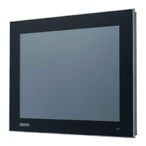
LS Industrial Systems XP30-BTA User manual

Right choice for ultimate yield
LSIS strives to maximize customers' profit in gratitude of choosing us for your partner.
Human Machine Interface
XGT Panel Communication
User’s Manual
z
Read this manual carefully before
installing, wiring, operating, servicing
or inspecting this equipment.
zKeep this manual within easy reach
for quick reference.
XGT Panel Series
http://eng.lsis.biz
XP30-BT
A
XP30-TTE
XP30-TT
A
XP30-BTE
XP50-TT
A
XP70-TT
A
XP80-TT
A
XP90-TT
A

Safety Instruction
Before using the product …
For your safety and effective operation, please read the safety instructions
thoroughly before using the product.
► Safety Instructions should always be observed in order to prevent accident
or risk with the safe and proper use the product.
► Instructions are separated into “Warning” and “Caution”, and the meaning of
the terms is as follows;
This symbol indicates the possibility of serious injury
or death if some applicable instruction is violated
This symbol indicates the possibility of slight injury
or damage to products if some applicable instruction
is violated
► The marks displayed on the product and in the user’s manual have the
following meanings.
Be careful! Danger may be expected.
Be careful! Electric shock may occur.
► The user’s manual even after read shall be kept available and accessible to
any user of the product.
Warning
Caution

Safety Instruction
Safety Instructions when designing
Please, install protection circuit on the exterior of PLC to protect
the whole control system from any error in external power or PLC
module. Any abnormal output or operation may cause serious problem
in safety of the whole system.
- Install applicable protection unit on the exterior of PLC to protect
the system from physical damage such as emergent stop switch,
protection circuit, the upper/lowest limit switch, forward/reverse
operation interlock circuit, etc.
- If any system error (watch-dog timer error, module installation error,
etc.) is detected during CPU operation in PLC, the whole output is
designed to be turned off and stopped for system safety. However,
in case CPU error if caused on output device itself such as relay or
TR can not be detected, the output may be kept on, which may
cause serious problems. Thus, you are recommended to install an
addition circuit to monitor the output status.
Never connect the overload than rated to the output module nor
allow the output circuit to have a short circuit, which may cause a
fire.
Never let the external power of the output circuit be designed to
be On earlier than PLC power, which may cause abnormal output or
operation.
In case of data exchange between computer or other external
equipment and PLC through communication or any operation of
PLC (e.g. operation mode change), please install interlock in the
sequence program to protect the system from any error. If not, it
may cause abnormal output or operation.
Warning

Safety Instruction
Safety Instructions when designing
I/O signal or communication line shall be wired at least 100mm
away from a high-voltage cable or power line. If not, it may cause
abnormal output or operation.
Caution
Use PLC only in the environment specified in PLC manual or
general standard of data sheet. If not, electric shock, fire, abnormal
operation of the product or flames may be caused.
Before installing the module, be sure PLC power is off. If not,
electric shock or damage on the product may be caused.
Be sure that each module of PLC is correctly secured. If the
product is installed loosely or incorrectly, abnormal operation, error or
dropping may be caused.
Be sure that I/O or extension connecter is correctly secured. If
not, electric shock, fire or abnormal operation may be caused.
If lots of vibration is expected in the installation environment,
don’t let PLC directly vibrated. Electric shock, fire or abnormal
operation may be caused.
Don’t let any metallic foreign materials inside the product, which
may cause electric shock, fire or abnormal operation..
Caution

Safety Instruction
Safety Instructions when wiring
Prior to wiring, be sure that power of PLC and external power is
turned off. If not, electric shock or damage on the product may be
caused.
Before PLC system is powered on, be sure that all the covers of
the terminal are securely closed. If not, electric shock may be caused
Warning
Let the wiring installed correctly after checking the voltage rated
of each product and the arrangement of terminals. If not, fire,
electric shock or abnormal operation may be caused.
Secure the screws of terminals tightly with specified torque when
wiring. If the screws of terminals get loose, short circuit, fire or abnormal
operation may be caused.
*
Surely use the ground wire of Class 3 for FG terminals, which is
exclusively used for PLC. If the terminals not grounded correctly,
abnormal operation may be caused.
Don’t let any foreign materials such as wiring waste inside the
module while wiring, which may cause fire, damage on the product
or abnormal operation.
Caution

Safety Instruction
Safety Instructions for test-operation or repair
Safety Instructions for waste disposal
Don’t touch the terminal when powered. Electric shock or abnormal
operation may occur.
Prior to cleaning or tightening the terminal screws, let all the
external power off including PLC power. If not, electric shock or
abnormal operation may occur.
Don’t let the battery recharged, disassembled, heated, short or
soldered. Heat, explosion or ignition may cause injuries or fire.
Warning
Don’t remove PCB from the module case nor remodel the module.
Fire, electric shock or abnormal operation may occur.
Prior to installing or disassembling the module, let all the external
power off including PLC power. If not, electric shock or abnormal
operation may occur.
Keep any wireless installations or cell phone at least 30cm away
from PLC. If not, abnormal operation may be caused.
Caution
Product or battery waste shall be processed as industrial waste.
The waste may discharge toxic materials or explode itself.
Caution

Revision History
Revision History
Version Date Contents Revised page
V 1.0 ’07.4 First Edition -
V 2.1 ’10. 7 Communication driver added
Error fixed
CH10~CH31
-
V 2.2 ’12.10 1) DELTADVP series driver added CH32
2) Fuji: MICREX-SX driver added CH33
3) AB DF-1 driver added CH34
4) HANYONG NUX Temperature Controller driver added CH35
5) RSAutomation: N/Nx-CCU driver added CH36
6) XGT Servo driver added CH37
7) HIGEN Servo driver added CH38
8) KDT Systems CIMON PLC LOADER driver added CH39
The number of User’s manual is indicated right part of the back cover.※
ⓒLS Industrial Systems Co., Ltd 2007 All Rights Reserved.

About the Manual
3
Thank you for purchasing the HMI of LS Industrial Systems Co., LTD.
For right use of the product, read carefully the manual to understand the functions, performance, installation and
programming of the product you have purchased before use it and make sure that this manual is delivered to the final user
and person in charge of maintenance.
The following manual deals with use of the product.
When necessary, read the following manuals and place an order.
Otherwise you can download PDF files by signing in our company’s home page http://eng.lsis.biz/.
Related Manuals
Title Contents Serial Number
XGT Panel
Communication User’s
Manual
This manual describes the line diagrams and communication
settings necessary for connecting the XGT Panel products to
control devices such as the PLC or inverter.
10310000758
XP-Builder User’s Manual
This is the XGT Panel software manual describing the functions
such as the display data, communication and environment
setting, logging/recipe data backup, simulator and printing to use
the XGT Panel products.
10310000759
XGT Panel User’s
Manual
This manual explains the specifications, features and system
composition of the XGT Panel series. 10310000757
XP-Manager
User’s Manual
XP-Manager is software supporting diverse functions of XGT
Panel. And communication between XGT Panels is available
through XP Link.
10310001111

Contents
1
Chapter 1 Introduction.....................................................................................................1-1 ~ 1-1
1.1 Guide to Use This Manual ......................................................................................................................1-1
Chapter 2 Communication Introduction and Configuration......................................2-1 ~ 2-9
2.1 Communication Introduction...................................................................................................................2-1
2.2 Communication Connector Configuration..............................................................................................2-1
2.2.1 RS-232C connector configuration ...............................................................................................2-1
2.2.2 RS-422/485 connector configuration...........................................................................................2-2
2.2.3 Ethernet connector configuration.................................................................................................2-2
2.3 Communication Specification..................................................................................................................2-3
2.3.1 RS-232C specification..................................................................................................................2-2
2.3.2 RS-422/485 specification .............................................................................................................2-3
2.3.3 Ethernet specification....................................................................................................................2-4
2.4 Communication Cable.............................................................................................................................2-4
2.4.1 RS-232C cable..............................................................................................................................2-4
2.4.2 RS-422/485 cable.........................................................................................................................2-5
2.4.3 Ethernet cable...............................................................................................................................2-5
2.5 Wiring Method..........................................................................................................................................2-5
2.5.1 RS-232C cable..............................................................................................................................2-5
2.5.2 RS-422/485 cable.........................................................................................................................2-6
2.5.3 Ethernet cable...............................................................................................................................2-8
Chapter 3 LSIS: MASTER-K PLC.................................................................................3-1 ~ 3-10
3.1 PLC List....................................................................................................................................................3-1
3.2 Wiring Diagram........................................................................................................................................3-2
3.2.1 CPU module direct connection method ......................................................................................3-2
3.2.2 Link method: Built-in Cnet............................................................................................................3-2
3.2.3 Link method: Cnet.........................................................................................................................3-3
3.2.4 Link method: FEnet.......................................................................................................................3-4
3.3 Communication Setting...........................................................................................................................3-5
3.3.1 CPU module direct connection method ......................................................................................3-5
3.3.2 Link method: Built-in Cnet............................................................................................................3-5
3.3.3 Link method: Cnet.........................................................................................................................3-7
3.3.4 Link method: FEnet.......................................................................................................................3-9
3.4Available Device.....................................................................................................................................3-10
Chapter 4 LSIS: GLOFA-GM PLC.................................................................................4-1 ~ 4-10
4.1 PLC List....................................................................................................................................................4-1
4.2 Wiring Diagram........................................................................................................................................4-2

Contents
2
4.2.1 CPU module direct connection method ......................................................................................4-2
4.2.2 Link method: Built-in Cnet............................................................................................................4-3
4.2.3 Link method: Cnet.........................................................................................................................4-3
4.2.4 Link method: FEnet.......................................................................................................................4-4
4.3 Communication Setting...........................................................................................................................4-5
4.3.1 CPU module direct connection method ......................................................................................4-5
4.3.2 Link method: Built-in Cnet............................................................................................................4-5
4.3.3 Link method: Cnet.........................................................................................................................4-7
4.3.4 Link method: FEnet.......................................................................................................................4-9
4.4Available Device.....................................................................................................................................4-10
Chapter 5 LSIS: XGK PLC...............................................................................................5-1 ~ 5-6
5.1 PLC List....................................................................................................................................................5-1
5.2 Wiring Diagram........................................................................................................................................5-1
5.2.1 CPU module direct connection method ......................................................................................5-1
5.2.2 Link method: Cnet.........................................................................................................................5-2
5.2.3 Link method: FEnet.......................................................................................................................5-3
5.3 Communication Setting...........................................................................................................................5-3
5.3.1 CPU module direct connection method ......................................................................................5-3
5.3.2 Link method: Cnet.........................................................................................................................5-4
5.3.3 Link method: FEnet.......................................................................................................................5-5
5.4Available Device.......................................................................................................................................5-6
Chapter 6 LSIS: XGB PLC...............................................................................................6-1 ~ 6-6
6.1 PLC List....................................................................................................................................................6-1
6.2 Wiring Diagram........................................................................................................................................6-1
6.2.1 CPU module direct connection method ......................................................................................6-1
6.2.2 Link method: Built-in Cnet............................................................................................................6-2
6.2.3 Link method: Cnet.........................................................................................................................6-3
6.3 Communication Setting...........................................................................................................................6-4
6.3.1 CPU module direct connection method ......................................................................................6-4
6.3.2 Link method: Built-in Cnet............................................................................................................6-4
6.3.3 Link method: Cnet.........................................................................................................................6-5
6.4Available Device.......................................................................................................................................6-6
Chapter7 LSIS: XGI PLC..................................................................................................7-1 ~ 7-6
7.1 PLC List....................................................................................................................................................7-1
7.2 Wiring Diagram........................................................................................................................................7-1
7.2.1 CPU module direct connection method ......................................................................................7-1
7.2.2 Link method: Cnet.........................................................................................................................7-2
7.2.3 Link method: FEnet.......................................................................................................................7-3

7.3 Communication Setting...........................................................................................................................7-3

Contents
3
7.3.1 CPU module direct connection method ......................................................................................7-3
7.3.2 Link method: Cnet.........................................................................................................................7-4
7.3.3 Link method: FEnet.......................................................................................................................7-5
7.4Available Device.......................................................................................................................................7-6
Chapter 8 MITSUBISHI: MELSEC-Q PLC....................................................................8-1 ~ 8-12
8.1 PLC List....................................................................................................................................................8-1
8.2 Wiring Diagram........................................................................................................................................8-2
8.2.1 CPU direct connection method....................................................................................................8-2
8.2.2 Link method: Cnet.........................................................................................................................8-3
8.2.3 Link method: FEnet.......................................................................................................................8-4
8.3 Communication Setting...........................................................................................................................8-5
8.3.1 Link method: Cnet.........................................................................................................................8-5
8.3.2 Link method: FEnet.......................................................................................................................8-6
8.4Available Device.....................................................................................................................................8-12
Chapter 9 SYMBOL: Bar Code Scanner.........................................................................9-1~9-4
9.1 Bar Code Scanner List............................................................................................................................9-1
9.2 Wiring Diagram........................................................................................................................................9-1
9.3 Communication Setting...........................................................................................................................9-2
Chapter 10 LS Industrial Systems : Inverter(MODBUS)..........................................10-1~10-7
10.1 Inverter List...........................................................................................................................................10-1
10.2 Wiring Diagram....................................................................................................................................10-2
10.2.1RS-485 Communication Type ..................................................................................................10-2
10.3 Communication Setting.......................................................................................................................10-3
10.4 Available Device ..................................................................................................................................10-6
Chapter 11 LS Industrial Systems: Inverter(LS BUS)...............................................11-1~11-6
11.1 Inverter List...........................................................................................................................................11-1
11.2 Wiring Diagram....................................................................................................................................11-2
11.2.1RS-485 Communication Type...................................................................................................11-2
11.3 Communication Setting.......................................................................................................................11-3
11.4 Available Device...................................................................................................................................11-6
Chapter 12 MODBUS RTU Protocol (Master)............................................................12-1~12-7
12.1 MODBUS Protocol Outline.................................................................................................................12-1

Contents
4
12.1.1 Frame Structure...........................................................................................................................12-1
12.1.2 Displaying Data andAddress...................................................................................................12-2
12.2 Wiring Diagram....................................................................................................................................12-2
12.2.1 RS-232C....................................................................................................................................12-2
12.2.2 RS-422 ......................................................................................................................................12-3
12.2.3 RS-485 ......................................................................................................................................12-3
12.3 Communication Setting.......................................................................................................................12-4
12.3.1 The example of setting PLC(XGK)..........................................................................................12-4
12.3.2The example of setting XGT Panel ...............................................................................................12-6
12.4 Available Device ..................................................................................................................................12-7
Chapter 13 MODBUS TCP/IP Protocol (Master)........................................................13-1~13-6
13.1 PLC allowed to be connected.............................................................................................................13-1
13.2 Wiring Diagram....................................................................................................................................13-1
13.3 Communication Setting.......................................................................................................................13-3
13.3.1 The example to set PLC(XGK)................................................................................................13-3
13.3.2 The example to set XGTPanel................................................................................................13-5
13.4 Available Device ..................................................................................................................................13-6
Chapter 14 MITSUBISHI: MELSEC-APLC ...............................................................14-1~14-10
14.1PLC List.................................................................................................................................................14-1
14.2 Wiring Diagram....................................................................................................................................14-2
14.2.1Link type: Cnet...........................................................................................................................14-2
14.3 Communication Setting.......................................................................................................................14-4
14.3.1Link type: Cnet...........................................................................................................................14-4
14.4 Available Device ..................................................................................................................................14-9
Chapter 15 OMRON: CS/CJ PLC...............................................................................15-1~15-13
15.1PLC List.................................................................................................................................................15-1
15.2 Wiring Diagram....................................................................................................................................15-2
15.2.1 CPU Mode.................................................................................................................................15-2
15.2.2 Link mode: Cnet........................................................................................................................15-3
15.2.3Link Mode: FEnet.......................................................................................................................15-5
15.3 Communication Setting.......................................................................................................................15-6
15.3.1 CPU Mode.................................................................................................................................15-6
15.3.2Link Mode: Cnet.........................................................................................................................15-7
15.3.3Link Mode: FEnet.................................................................................................................... 15-10
15.4 Available Device ............................................................................................................................... 15-13

Contents
5
Chapter 16 OEMax Controls : Nx-CCU+ ....................................................................16-1~16-6
16.1 Available PLC.......................................................................................................................................16-1
16.2 Wiring Diagram....................................................................................................................................16-1
16.2.1 RS-232C Connection...............................................................................................................16-1
16.2.2 RS-485 Connection..................................................................................................................16-2
16.3 Communication Setting.......................................................................................................................16-3
16.3.1 PLC(OEMax) Setting................................................................................................................16-3
16.3.2 XGT Panel Setting....................................................................................................................16-5
16.4 Available Device ..................................................................................................................................16-6
Chapter 17 AB: EtherNet/IP...........................................................................................17-1~17-8
17.1 Available PLC.......................................................................................................................................17-1
17.2 Control/CompactLogix Series (EtherNet/IP)......................................................................................17-1
17.2.1 Connection................................................................................................................................17-1
17.2.2 Communication Setting............................................................................................................17-3
17.3 MicroLogix Series (EtherNet/IP).........................................................................................................17-4
17.3.1 Connection................................................................................................................................17-4
17.3.2 Communication Setting............................................................................................................17-5
17.3.3 Device Nomenclature...............................................................................................................17-6
17.4 Available Device ..................................................................................................................................17-7
Chapter 18 MODBUS RTU PROTOCOL(Slave).........................................................18-1~18-9
18.1 Communication Setting.......................................................................................................................18-1
18.1.1 The example of PLC(XGT) setting..........................................................................................18-1
18.1.2 XGT Panel Setting....................................................................................................................18-4
18.2Available Device...................................................................................................................................18-6
18.2.1DeviceArea................................................................................................................................18-6
18.2.2 HS Device .................................................................................................................................18-6
Chapter 19 MODBUS TCP/IP Protocol (Slave)........................................................19-1~19-10
19.1 Communication Setting.......................................................................................................................19-1
19.1.1 The example of PLC(XGT) setting..........................................................................................19-1
19.1.2 XGT Panel Setting....................................................................................................................19-4
19.2Available Device...................................................................................................................................19-6
19.2.1 DeviceArea...............................................................................................................................19-6
19.2.2 HS Device .................................................................................................................................19-6

Contents
6
Chapter 20 YASKAWA MEMOBUS RTU(Master).......................................................20-1~20-6
20.1 PLC List................................................................................................................................................20-1
20.1.1Available Device List.....................................................................................................................20-1
20.1.2 Description on Protocol.............................................................................................................20-1
20.2 Wiring Diagram....................................................................................................................................20-2
20.2.1 Link Mode..................................................................................................................................20-2
20.3 Communication Setting.......................................................................................................................20-3
20.3.1 Link Mode..................................................................................................................................20-3
20.4 Available Device ..................................................................................................................................20-6
Chapter 21 KDT PLC......................................................................................................21-1~21-5
21.1 PLC List................................................................................................................................................21-1
21.2 Wiring Diagram....................................................................................................................................21-1
21.2.1 Link Mode..................................................................................................................................21-1
21.3 Communication Setting.......................................................................................................................21-3
21.3.1 Link Mode..................................................................................................................................21-3
21.4 Available Device ..................................................................................................................................21-5
Chapter 22 MITSUBISHI: MELSEC-FX PLC...............................................................22-1~22-6
22.1 PLC List................................................................................................................................................22-1
22.2 Wiring Diagram....................................................................................................................................22-2
22.2.1 Link Mode..................................................................................................................................22-2
22.3 Communication Setting.......................................................................................................................22-4
22.3.1 Link Mode..................................................................................................................................22-4
22.4 Available Device ..................................................................................................................................22-6
Chapter 23 Parker: Hi-Driver......................................................................................23-1~23-11
23.1Inverter List............................................................................................................................................23-1
23.2 Wiring Diagram....................................................................................................................................23-2
23.2.1 RS-485 Communication Mode................................................................................................23-2
23.2.2 RS-422 Communication Mode................................................................................................23-3
23.3 Communication Setting.......................................................................................................................23-5
23.4 Available Device ..................................................................................................................................23-8
23.4.1 Basic Parameters .....................................................................................................................23-8

Contents
7
23.4.2 Basic Commands...................................................................................................................23-11
Chapter 24 Siemens: S7 200 PPI Direct .....................................................................24-1~24-7
24.1 PLC List................................................................................................................................................24-1
24.2 Wiring Diagram....................................................................................................................................24-2
24.2.1 RS-485 Communication...........................................................................................................24-2
24.3 Communication Setting.......................................................................................................................24-3
24.3.1 Setting S7 200 PPI Direct.........................................................................................................25-3
24.4 Available Device ..................................................................................................................................24-6
Chapter 25 Siemens: S7 300/400 MPI Driver.............................................................25-1~25-9
25.1 PLC List................................................................................................................................................25-1
25.2 Wiring Diagram....................................................................................................................................25-2
25.2.1 RS-232C communication.........................................................................................................25-2
25.3 Communication Setting.......................................................................................................................25-7
25.3.1 Setting S7 300/400 PCAdapter...............................................................................................25-7
25.4 Available Device ..................................................................................................................................25-8
Chapter 26 Siemens: S7 3964(R)/RK512 Driver......................................................26-1~26-11
26.1 PLC List................................................................................................................................................26-1
26.2 Wiring Diagram....................................................................................................................................26-2
26.2.1 RS-232C communication.........................................................................................................26-2
26.2.2 RS-422/485(4wire) Communication........................................................................................26-2
26.3 Communication Setting.................................................................................................................... 26-10
26.3.1 Setting S7 300/400 3964(R)/RK512........................................................................................... 26-10
26.4 Available Device ................................................................................................................................26-11
Chapter 27 MITSUBISHI: MELSEC-FX CPU Driver ..................................................27-1~27-9
27.1 PLC List................................................................................................................................................27-1
27.2 Wiring Diagram....................................................................................................................................27-2
27.2.1 RS-232C communication method...........................................................................................27-2
27.2.2 RS-422 (4wire) communication method.................................................................................27-2
27.3 Communication Setting.......................................................................................................................27-4
27.3.1 MITSUBISHI MELSEC-FX CPU configuration......................................................................27-4
27.4 Available Device ..................................................................................................................................27-5
27.4.1 Devices available for FX CPU ............................................................................................27-5

Contents
8
Chapter 28 LS Mecapion..............................................................................................28-1~28-3
28.1 List of devices available to connect....................................................................................................28-1
28.2 Wiring Diagram....................................................................................................................................28-1
28.2.1 Direct connection type..............................................................................................................28-1
28.3 Communication Setting.......................................................................................................................28-2
28.3.1 Direct connection type..............................................................................................................28-2
28.4 Available Device ..................................................................................................................................28-3
Chapter 29 Modbus ASCII Master...............................................................................29-1~29-7
29.1 Modbus Protocol Overview.................................................................................................................29-1
29.1.1 Frame structure.........................................................................................................................29-1
29.1.2 Data and address.....................................................................................................................29-2
29.2 Wiring Diagram....................................................................................................................................29-2
29.2.1 RS-232C ...................................................................................................................................29-2
29.2.2 RS-422......................................................................................................................................29-3
29.2.3 RS-485......................................................................................................................................29-3
29.3 Communication Setting.......................................................................................................................29-4
29.3.1 Example of PLC(XGK) configuration ......................................................................................29-4
29.3.2 Example configuration of XGT Panel......................................................................................29-6
29.4 Available Device ..................................................................................................................................29-7
Chapter 30 Modbus ASCII slave..................................................................................30-1~30-9
30.1 Communication Setting.......................................................................................................................30-1
30.1.1 Example of PLC(XGK) configuration.............................................................................................30-1
30.1.2 XGT Panel configuration..........................................................................................................30-3
30.2 Available Device ..................................................................................................................................30-5
30.2.1 Device area...............................................................................................................................30-5
30.2.2 HS devices................................................................................................................................30-5
Chapter 31 User-defined Protocol ............................................................................31-1~31-16
31.1 Communication Setting.......................................................................................................................31-1
31.1.1 Configuration of PLC................................................................................................................31-1
31.1.2 Configuration of XGT Panel.....................................................................................................31-1
31.2 Available Device ..................................................................................................................................31-3

Contents
9
31.2.1 Devices area.............................................................................................................................31-3
31.3 Usage of script.....................................................................................................................................31-4
31.3.1 Script function – Communication script function.....................................................................31-4
31.3.2 Transmit data when switch is pushed .....................................................................................31-7
31.3.3 Regular monitoring for devices............................................................................................. 31-10
31.3.4 Read data received only from the controller........................................................................ 31-13
Chapter 32 DELTA DVP series.....................................................................................32-1~32-5
32.1 PLC List................................................................................................................................................32-1
32.2 Wiring Diagram....................................................................................................................................32-2
32.2.1 RS-232C communication method...........................................................................................32-2
32.3 Communication Setting.......................................................................................................................32-3
32.3.1 DELTADVP configuration........................................................................................................32-3
32.4 Transmit data when switch is pushed……………………………………………………………….32-4
32.4.1 Devices available for DELTADVP EH.....................................................................................32-5
Chapter 33 Fuji: MICREX-SX Series SIO....................................................................33-1~33-7
33.1 PLC List................................................................................................................................................33-1
33.2 Wiring Diagram....................................................................................................................................33-2
33.2.1 RS-232C communication method...........................................................................................33-2
33.2.2 RS-422 communication method..............................................................................................33-4
33.3 Communication Setting………………………………………………………………………………33-5
33.3.1 FUJI MICREX-SX Link configuration......................................................................................33-5
33.4 Available devices.................................................................................................................................33-6
33.4.1 Transmit data when switch is pushed………………………………………………………..33-6
Chapter 34AB: PLC DF-1............................................................................................34-1~34-13
34.1 PLC List................................................................................................................................................34-1
34.2 Wiring Diagram....................................................................................................................................34-2
34.2.1 Control/CompactLogix Series RS-232C communication ......................................................34-2
34.2.2 MicroLogix Series RS-232C communication..........................................................................34-3
34.3 Communication Setting.......................................................................................................................34-4
34.3.1 AB Control/CompactLogix and MicroLogix setting.................................................................34-4
34.4 Available Device..................................................................................................................................34-8
34.4.1 The devices available in the CompactLogix ...........................................................................34-8
34.4.2 The device available in the MicroLogix……………………………………………………...34-10
34.4.3 Control/CompactLogix device naming rule………………………………………………….34-12
34.4.4
MicroLogix device naming rule ………………………………………………………………34-13

Contents
10
Chapter 35 HANYOUNG NUX: Temperature Controller..........................................35-1~35-6
35.1 PLC List................................................................................................................................................35-1
35.2 Wiring Diagram....................................................................................................................................35-2
35.2.1 RS-485 communication method..............................................................................................35-2
35.2.2 RS-422 communication method..............................................................................................35-4
35.3 Communication Setting.......................................................................................................................35-5
35.4 Available devices.................................................................................................................................35-4
32.4.1 Devices available for Fuji MICREX-SX...................................................................................35-6
Chapter 36 RS Automation: N/NX-CCU......................................................................36-1~36-8
36.1 PLC List................................................................................................................................................36-1
36.2 RS-232C connection...........................................................................................................................36-3
36.3 Communication Setting.......................................................................................................................36-5
36.3.1 Available devices ......................................................................................................................36-5
36.3.2 XGT Panel configuration..........................................................................................................36-6
36.4Available Devices.................................................................................................................................36-8
Chapter 37 LSIS: XGT Servo........................................................................................37-1~37-5
37.1 Servo List .............................................................................................................................................37-1
37.2 Wiring Diagram....................................................................................................................................37-2
37.2.1 RS-232C connection................................................................................................................37-2
37.2.2 RS-485 connection...................................................................................................................37-2
37.3 Communication Setting.......................................................................................................................37-3
37.3.1 Servo Configuration..................................................................................................................37-3
37.3.2 Servo Configuration..................................................................................................................37-3
37.4Available devices.................................................................................................................................37-5
Chapter 38 HIGEN: Servo.............................................................................................38-1~38-6
38.1 Servo List .............................................................................................................................................38-1
38.2 Wiring Diagram....................................................................................................................................38-2
38.2.1 RS-232C connection................................................................................................................38-2
38.2.2 RS-485 connection...................................................................................................................38-3
38.3 Communication Setting.......................................................................................................................38-4
38.3.1 Servo Configuration..................................................................................................................38-4
38.3.2 XGT Panel Configuration.........................................................................................................38-4
38.4Available devices.................................................................................................................................38-6

Contents
11
Chapter 39 KDT Systems: CIMON PLC LOADER....................................................39-1~39-5
39.1 PLC List................................................................................................................................................39-1
39.2 RS-232C connection...........................................................................................................................39-2
39.3 Communication Setting.......................................................................................................................39-3
39.3.1 CIMON PLC LOADER configuration......................................................................................39-3
39.4Available Devices.................................................................................................................................39-4
39.4.1 BP Series...................................................................................................................................39-4
39.4.1 CP Series ..................................................................................................................................39-4
Appendix 1 Warranty and Environmental Policy ..........................................................App1-1

Chapter 1 Introduction
1-1
Chapter 1 Introduction
1.1 Guide to Use This Manual
This manual includes system configuration, wiring diagram, available device and setting between controllers such as PLC, inverter and the
XGT Panel.
It is dividedinto chapters as follows.
No. Title Contents
Chapter1 Introduction Describes configuration of this manual, unit’s features and terminology.
Chapter2 Communication Introduction and Configuration Describes communication, port provided by XGT Panel.
Chapter3 LSIS: MASTER-K PLC Describes communication connection with LSIS MASTER-K PLC.
Chapter4 LSIS: GLOFA-GM PLC Describes communication connection with LSIS GLOFA-GM PLC.
Chapter5 LSIS: XGK PLC Describes communication connection with LSIS XGK PLC.
Chapter6 LSIS: XGB PLC Describes communication connection with LSIS XGB PLC.
Chapter7 LSIS: XGI PLC Describes communication connection with LSIS XGI PLC.
Chapter8 MITSUBISHI MELSEC-Q PLC Describes communication connection with MITSUBISHI MELSEC-Q
PLC.
Chapter9 SYMBOL: Bar Code Scanner Describes communication connection with SYMBOL’s Bar Code
Scanner.
Chapter10 LSIS: Inverter (MODBUS) Describes communication connection with LSIS: Inverter (MODBUS)
Chapter11 LSIS: Inverter(LS BUS) Describes communication connection with LSIS: Inverter (LSBUS)
Chapter12 Modbus RTU(Master) Describes communication connection with Modbus RTU(Master)
Chapter13 Modbus TCP/IP(Master) Describes communication connection with Modbus TCP/IP(Master)
Chapter14 MITSUBISHIMELSEC-APLC Describes communication connection with MITSUBISHI MELSEC-A
PLC
Chapter15 OMRON CS/CJ PLC Describes communication connection with OMRONCS/CJ PLC
Chapter16 OEMax Controls: Nx-CCU+ Describes communication connection with OEMax Controls:Nx-CCU+
Chapter17 AB EtherNet/IP Describes communication connection with AB EtherNet/IP
Chapter18 Modbus RTU (Slave) Describes communication connection with Modbus RTU(Slave)
Chapter19 Modbus TCP/IP (Slave) Describes communication connection with Modbus TCP/IP (Slave)
Chapter20 YASKAWAMEMOBUSRTU(Master) Describes communication connection with YASKAWA MEMOBUS
RTU (Master)
Chapter21 KDT PLC Describes communication connection with KDT PLC
Chapter22 MITSUBISHI:MELSEC-FXPLC Describes communication connection with MITSUBISHI: MELSEC-FX
PLC
Chapter23 Parker:Hi-Drive Describes communication connection with Parker: Hi-Drive
Chapter24 Siemens: S7 200 PPI Direct Describes communication connection with Siemens: S7 200 PPI Direct
This manual suits for next models
7
Table of contents